Contents HP E1459A 64-Channel Isolated Input Interrupt Module Edition 3 Warranty ....................................................................................................................... 5 Safety Symbols ............................................................................................................. 6 WARNINGS................................................................................................................. 6 Declaration of Conformity ................................
Chapter 3 HP E1459A SCPI Command Reference .................................................................... 39 DIAGnostic:SYSReset Subsystem ............................................................................. 41 DIAGnostic:SYSReset[:STATe]? ....................................................................... 41 DIAGnostic:SYSReset:ENABle ............................................................ 41 DIAGnostic:SYSReset:ENABle? .......................................................
STATus:QUEStionable:CONDition? ................................................................. 66 STATus:QUEStionable:ENABle .......................................................... 66 STATus:QUEStionable:ENABle? ...................................................................... 67 STATus:QUEStionable[:EVENt]? ...................................................................... 67 SYSTem Subsystem ..............................................................................................
Contents
Certification Hewlett-Packard Company certifies that this product met its published specifications at the time of shipment from the factory. HewlettPackard further certifies that its calibration measurements are traceable to the United States National Institute of Standards and Technology (formerly National Bureau of Standards), to the extent allowed by that organization's calibration facility, and to the calibration facilities of other International Standards Organization members.
Documentation History All Editions and Updates of this manual and their creation date are listed below. The first Edition of the manual is Edition 1. The Edition number increments by 1 whenever the manual is revised. Updates, which are issued between Editions, contain replacement pages to correct or add additional information to the current Edition of the manual. Whenever a new Edition is created, it will contain all of the Update information for the previous Edition.
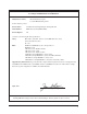
Declaration of Conformity according to ISO/IEC Guide 22 and EN 45014 Manufacturer's Name: Hewlett-Packard Company Loveland Manufacturing Center declares, that the product: Product Name: 64-Channel Isolated Digital Input / Interrupt Module Model Number: HP E1459A (formerly HP Z2404B) Product Options: All conforms to the following Product Specifications: Safety: IEC 1010-1 (1990) Incl. Amend 1 (1992)/EN61010-1/A2 (1995) CSA C22.2 #1010.
Notes: 8
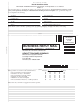
Please fold and tape for mailing Reader Comment Sheet HP E1459A / Z2404B 64-Channel Isolated Input / Interrupt Module User’s Manual Edition 3 You can help us improve our manuals by sharing your comments and suggestions. In appreciation of your time, we will enter you in a quarterly drawing for a Hewlett-Packard Palmtop Personal Computer (U.S. government employees are not eligible for the drawing).
Chapter 1 Installing and Configuring the HP E1459A The HP E1459A 64-Channel Isolated Digital Input/Interrupt module (formerly known as the HP Z2404B1) provides 64 isolated digital input channels configured as four 16-bit ports. The module is used for sensing signals and detecting edge changes on digital inputs. The module is a C-Size VXIbus register-based product that operates in a C-Size VXIbus mainframe.
To VXIbus Transceivers Figure 1-1.
The HP E1459A can be programmed to monitor channel occurrences either internally with a 1.0 MHz sample clock, or externally, with a sourced capture clock. Using either clocking technique, data channels may function as edge detect inputs and/or data capture inputs. Events at any channel may occur simultaneously or in overlap with events on any other channel. Figure 1-2 is a block diagram of the hardware interrupt resolver circuit.
Watchdog Timer The HP E1459A provides a programmable timer facility which, in the event of time-out, will generate a "system wide" reset to all other card-cage modules. This timer may be disabled by the SCPI command DIAG:SYSR:ENAB OFF. Input Level Selection Each channel is capable of operation over an input range from 2.0 through 60.0 Vdc. Input voltages are grouped into voltage ranges which are selected via a series of jumpers on the module.
Caution The user MUST ensure, based upon the programmed debounce period and internal delays, that data to be captured has propagated the debouncers and is fully setup prior to the assertion of the externally generated capture clock. The module has two primary modes of operation: the module can interrupt your software when an event occurs or your software can periodically poll the module to determine if an event has occurred.
Edge Detection Examples Figure 1-3 demonstrates a typical example. A channel that has been programmed to detect both positive and negative edge transitions posts a marker at the occurrence of a positive edge. Before user software can service this interrupt, a negative transition occurs and is detected. Because both are detected and the events are marked, user software first reads the positive edge detect register and then the negative edge detect register. Figure 1-3.
Input Data Capture The state of any channel, within any channel group, may be captured for subsequent processing (as data) by an externally sourced capture clock (XTRIG0N - XTRIG3N, the external trigger inputs for each port). Data channels may be interspersed among all 64 channel inputs, but the user is cautioned to ensure that all setup criteria and clock sources coincide with requirements for synchronization.
Front Panel Markers Interrupt Driven or Polled Mode Operations Interrupt Parsing All "Data Available" and "Edge Detect" marker bits are physically available via the HP E1459A front panel. These outputs are TTL/HC compatible and may be used to trigger other system-wide events or to provide logging information for statistical tracking or other performance analysis purposes. Interrupts may be programmatically disabled for both edge-detect and data-capture events.
Configuring for Installation Before installing the module you should verify that the following jumpers and switches are set correctly. • Logical Address dip switch • Interrupt priority jumper positions • Input threshold levels • Reset time of the Watchdog Timer WARNING SHOCK HAZARD. Only qualified, service-trained personnel who are aware of the hazards involved should install, configure, or remove the module.
Setting the Logical Address Each module within the VXIbus mainframe must be set to a unique logical address. The setting is controlled by an 8 pin dip switch. This allows for values from 0 to 255. The factory setting of this switch is decimal 144. No two modules in the same mainframe can have the same logical address. The location is shown in Figure 1-5.
Setting Input Threshold Levels Ch 0 The threshold levels for each channel can be set independently. A six pin plug with a two pin shorting jack is provided for each channel. The channel can be identified from the silk-screen on the board. Each jumper is labeled JXCC, where J indicates jumper, X is a number that can be ignored and CC indicates channel number. The default factory setting is for 5 volts. Pin 1 can be identified by the square pad on the bottom of the board.
Connecting User Inputs The HP E1459A Isolated Digital Input/Interrupt module consists of a component module and a terminal block. User inputs for each channel consists of a low and a high connection for each channel. The inputs will only detect signals of a positive polarity. A logical "1" will only be detected if the high terminal is at a higher potential than the low terminal. It must also meet the drive requirements for the voltage threshold selected.
A 32 31 30 29 28 27 26 25 24 23 22 21 20 19 18 17 16 15 14 13 12 11 10 9 8 7 6 5 4 3 2 1 CH 00 HI CH 01 HI CH 02 HI CH 04 HI CH 05 HI CH 06 HI CH 07 HI CH 08 HI CH 09 HI CH 10 HI CH 11 HI CH 13 HI CH 14 HI CH 15 HI CH 16 HI CH 17 HI CH 18 HI CH 19 HI CH 20 HI CH 21 HI CH 22 HI CH 23 HI CH 25 HI CH 26 HI CH 27 HI CH 28 HI CH 29 HI CH 30 HI CH 31 HI CH 32 HI CH 33 HI CH 34 HI 32 31 30 29 28 27 26 25 24 23 22 21 20 19 18 17 16 15 14 13 12 11 10 9 8 7 6 5 4 3 2 1 CH 35 HI CH 36 HI CH 37 HI CH 38 HI CH 40 HI
Installing the HP E1459A in a VXIbus Mainframe The HP E1459A may be installed in any C-size VXIbus mainframe slot (except slot 0). Refer to Figure 1-8 to install the module in a mainframe. 1 Set the extraction levers out. 2 Slide the module into any slot (except slot 0) until the backplane connectors touch. Extraction Levers 3 Seat the module into the mainframe by pushing in the extraction levers 4 Tighten the top and bottom screws to secure the module to the mainframe.
Terminal Block The HP E1459A includes both the input / interrupt module and a screw-type standard terminal block. User inputs to the terminal block are to the High and Low for each channel, +5Volt, Ground, Data Valid (DAV0 - DAV3), External Trigger (XTRIG0 - XTRIG3), and Interrupt (INTR0 - INTR3) . Figure 1-9 shows the HP E1459A’s standard screw-type terminal block connectors and associated channel numbers. Use the guidelines below to wire connections.
Wiring a Terminal Block The following illustrations show how to connect field wiring to the terminal block.
5 Replace Wiring Exit Panel 6 Replace Clear Cover A. Hook in the top cover tabs onto the fixture B.
Installing and Configuring the HP E1459A
Chapter 2 Using the HP E1459A Module This chapter provides examples of using and programming the HP E1459A using the Standard Commands for Programmable Instrumentation (SCPI). For detailed information on all the SCPI commands for this module, refer to Chapter 3. Appendix B in this manual provides information on registers and register-based programming. Note If you are controlling the module by a high level language, such as the downloaded SCPI driver or the VXIplug&play driver, do not do register writes.
Power-on / Reset States At power-on or reset (*RST) the HP E1459A is set to the following conditions: • Watchdog timer is off (disabled). • Clock Source is Internal • Input Debounce Time is 18.0 µS. • DAV (Data Available) Event interrupts are disabled for all ports. • Edge Event interrupts are disabled for all ports. Also, refer to the STATus:PRESet command in Chapter 3.
/* Send the Self Test Command */ errStatus = viQueryf (E1459, "*TST?\n","%t",selftst_string); if (VI_SUCCESS > errStatus){ printf("ERROR: viQueryf() returned 0x%x\n",errStatus); return errStatus;} printf("Self Test Result is %s\n",selftst_string); /* Query the ID string */ errStatus = viQueryf (E1459, "*IDN?\n","%t",id_string); if (VI_SUCCESS > errStatus){ printf("ERROR: viQueryf() returned 0x%x\n",errStatus); return errStatus;} printf("IDN? returned %s\n",id_string); /* Close Sessions */ errStatus = viClos
Digital Input The HP E1459A is capable of simple digital inputs on any of the individual four ports or combined Ports 0 and 1 or Ports 2 and 3.
/* Query Ports 2 and 3 as a 32-bit word */ errStatus = viQueryf(E1459, "MEAS:DIG:DATA2:LWORD:VAL?\n","%t", val1); if (VI_SUCCESS > errStatus){ printf("ERROR: viQueryf() returned 0x%x\n",errStatus); return errStatus;} printf("Value returned %i\n",val1); /* Close Sessions */ errStatus = viClose (E1459); if (VI_SUCCESS > errStatus){ printf("ERROR: viClose() returned 0x%x\n",errStatus); return 0;} errStatus = viClose (viRM); if (VI_SUCCESS > errStatus){ printf("ERROR: viClose() returned 0x%x\n",errStatus); retu
Edge Detected Event Detection The HP E1459A can respond to two types of events: Edge Events (either negative edge, positive edge, or both) and Data Available. Figures 2-1 and 2-2 show the general flow of commands necessary to program the HP E1459A to detect events. Figure 2-1 shows the flow for Edge Event Detection, Figure 2-2 shows the flow for Data Available Event Detection.
HP E1459A Edge Event Detection Flowchart Unmask all 16 bits of Port. (Either Positive, Negative, or both.) Optionally, set the Debounce Time Enable the Edge Detection Wait for the Event to Occur. Do one of the following: 1. Poll the Port Summary Register 2. Poll the Status Subsystem 3.
HP E1459A Data Available Event Detection Flowchart INPutn:CLOCk[:SOURce]EXT Set External Clock Source Optionally, set the Debounce Time Enable the DAV Detection Wait for the Event to Occur. Do one of the following: 1. Poll the Port Summary Register 2. Poll the Status Subsystem 3.
Example 3: Edge Interrupt This example repeatedly polls the Port 0 Port Summary Edge Detection Register to determine when an edge event occurs. When an event occurs, the program reads the values of the Positive and Negative Edge Registers and returns the values. The values returned are in the range of -32768 to +32767.
if (VI_SUCCESS > errStatus){ printf("ERROR: viPrintf() returned 0x%x\n",errStatus); return errStatus;} /* Enable Port 0 Edge Detection */ errStatus = viPrintf (E1459, "EVEN:PORT0:EDGE:ENAB ON\n"); if (VI_SUCCESS > errStatus){ printf("ERROR: viPrintf() returned 0x%x\n",errStatus); return errStatus;} /* Loop and poll Port Summary Register until event occurs */ while (event = 0) { errStatus = viQueryf (E1459, "EVEN:PSUM:EDGE?\n","%t",event); if (VI_SUCCESS > errStatus){ printf("ERROR: viPrintf() returned 0x%x\
Chapter 3 HP E1459A SCPI Command Reference The Standard Commands for Programmable Instruments (SCPI) commands described in this chapter are only available in the downloadable SCPI driver for the HP Command Modules such as the HP E1406. If you are not using a command module, you should use the HP VXIplug&play driver. This driver is available on the HP Instrument Drivers CD and available on the World Wide Web. Common Command Format The IEEE 488.
For example, if the command syntax shows DISPlay , then DISP and DISPLAY are both acceptable forms. Other forms of DISPlay, such as DISPL or DISPl will generate an error. You may use upper or lower case letters. Therefore, DISPLAY, display , and DiSpLaY are all acceptable. Implied Commands Implied commands are those which appear in square brackets ([ ]) in the command syntax. (Note that the brackets are not part of the command and are not sent to the instrument.
DIAGnostic:SYSReset Subsystem The DIAGnostic:SYSReset Subsystem controls and monitors the Watchdog Timer. Refer to Chapter 1 for detailed information on the Watchdog Timer. Syntax DIAGnostic:SYSReset [:STATe]? :ENABle :ENABle? page 41 page 41 page 42 DIAGnostic:SYSReset[:STATe]? Returns the value of the Watchdog Timer state from the Watchdog Timer Control / Status Register. Parameters Comments None • Returns a 1 if the Watchdog Timer is asserted; returns a 0 if the Timer is not asserted.
DIAGnostic:SYSReset:ENABle? Returns the state of the Watchdog Timer as either a (unsigned) 1, or 0. Parameters Comments 42 None Returns a 1 if the Watchdog Timer is enabled. Returns a 0 if the Timer is not enabled.
DISPlay:MONitor Subsystem The DISPlay:MONitor subsystem turns on the monitor mode. Parameters related to the state of the data and control lines are shown on an external terminal1. Refer to the Command Module’s Users’s Guide for supported terminal types. The DISPlay:MONitor commands do not apply to any C-SCPI or VXIplug&play driver implementation.
DISPlay:MONitor:PORT? [MINimum | MAXimum | DEFault] Returns the number of the current display Port as +0, +1, +2, or +3. Parameters Comments None • When sent with no parameter, this query returns a decimal number indicating the Port being monitored. If AUTO was selected as the Port parameter in the DISP:MON:PORT command, the query returns the number of the most recently-viewed Port. If either MINimum or DEFault was specified, this query returns a +0.
DISPlay:MONitor[:STATe] Turns the Display Mode on or off. Parameters Comments Parameter Name Parameter Type Range of Values Default Numeric or discrete 0 | 1 | OFF | ON OFF • DISP:MON ON enables the terminal display of Port parameters. The parameters are updated to the terminal following each new command accessing a Port.
INPut Subsystem The INPut Subsystem configures the input de-bounce circuitry and specifies the input clock source. Syntax INPutn :CLOCk[:SOURce] page 46 :CLOCk[:SOURce]? page 47 :DEBounce:TIME
INPutn:CLOCk[:SOURce]? Returns the programmed value of the input clock source for Port n. Parameters Comments Example Parameter Name Parameter Type Range of Values Default INPutn numeric 0, 1, 2, 3 0 • The value returned is an unquoted string of EXT or INT. INPut2:CLOCk[:SOURce]? queries the input clock source for Port 2. INPutn:DEBounce:TIME
INPutn:DEBounce:TIME? [MINimum | MAXimum | DEFault] Returns the current debounce time for Port n as a floating point number formatted as +d.ddddddE±ddd Parameters Comments Parameter Name Parameter Type Range of Values Default INPutn
MEASure Subsystem The MEASure commands are used for the Isolated Digital Input part of the HP E1459A. These commands return data corresponding to the current value of the input signals. Refer to Chapter 2 for more examples of using the MEASure Subsystem. Syntax MEASure:DIGital:DATAn[:type][:VALue]? :DIGital:DATAn[:type]:BITm? page 49 page 50 MEASure:DIGital:DATAn[:type] [:VALue]? Returns the current data for the specified Port n as a signed integer.
MEASure:DIGital:DATAn[:type]:BITm? Returns the value of BIT m of the data for the specified Port n as a signed integer of either +0 or +1.
MEMory Subsystem This command accesses the SCPI memory subsystem. MEMory:DELete:MACRo Deletes the MACRO command defined by the name . Parameters Comments Parameter Name Parameter Type Range of Values Default discrete up to 12 alphanumeric characters None • The macro was previously defined using the *DMC Common Command. • The maximum length for is 12 characters. • This command deletes the single, named macro; the *PMC Common command purges all macros.
SENSe Subsystem The SENSe Subsystem configures Event Detection in the HP E1459A Module. The HP E1459A has an event detector for each 16 bit Port to detect positive or negative edge transitions and whether new data is available: DAV New data is available on the specified digital input port(s). NEDGe Negative Edge transition occurred on a specified digital input channel(s). PEDGe Positive Edge transition occurred on a specified digital input channel(s).
[SENSe:]EVENt:PORTn:DAVailable:ENABle Enables a Data Available interrupt to occur when new data is latched into Port n by an external clock source. Parameters Comments Parameter Name Parameter Type Range of Values Default PORTn numeric 0, 1, 2, 3 (PORT = PORT0) PORT0 numeric or discrete 0, 1, OFF, ON OFF • The clock source for Port n must be set to EXTernal and the event must be enabled. Otherwise, error -221, "Settings conflict" occurs.
[SENSe:]EVENt:PORTn:EDGE? Returns the status of the Edge Detect Event for Port n as either a a (unsigned) 0 or a 1. Parameters Comments Parameter Name Parameter Type Range of Values Default PORTn numeric 0, 1, 2, 3 (PORT = PORT0) PORT0 • A 0 means an edge event was not detected; a 1 means an edge event was detected. • An edge event must have been enabled by the [SENSe:]EVENt:PORTn:EDGE command and a Positive edge mask and/or Negative edge mask must be enabled and set to a non-zero value.
[SENSe:]EVENt:PORTn:EDGE:ENABle? Returns the state of the Edge Event Enable for Port n as a (unsigned) 0 or a 1. Parameters Comments Parameter Name Parameter Type Range of Values Default PORTn numeric 0, 1, 2, 3 (PORT = PORT0) PORT0 • A 0 means the Edge Event is not enabled; a 1 means it is enabled. [SENSe:]EVENt:PORTn:NEDGe? Returns the value of the Negative Edge Detect Register for all 16 bits of Port n.
[SENSe:]EVENt:PORTn:NEDGe:ENABle Sets the Negative Edge Detection Mask for Port n. Parameters Comments Parameter Name Parameter Type Range of Values Default PORTn numeric 0, 1, 2, 3 (PORT = PORT0) PORT0 numeric -32768 to +32767 (0000h to FFFFh) 0 • Each bit enables the corresponding channel negative edge detect for Port n. A 1 means the mask is enabled for that bit, a 0 means the mask is disabled for that bit. • *RST Condition: clears the mask (no enabled bits).
[SENSe:]EVENt:PORTn:PEDGe? Returns the value of the Positive Edge Detect Register for all 16 bits of Port n. Parameters Comments Parameter Name Parameter Type Range of Values Default PORTn numeric 0, 1, 2, 3 (PORT = PORT0) PORT0 • The value returned is in the range of -32768 to +32767.
[SENSe:]EVENt:PORTn:PEDGe:ENABle? Returns the decimal value of the Positive Edge Detection Mask as a 16 bit integer. Parameters Comments Parameter Name Parameter Type Range of Values Default PORTn numeric 0, 1, 2, 3 (PORT = PORT0) PORT0 • Returns a number in the range of -32768 to +32767. • Each bit enables the corresponding channel positive edge detect mask for Port n. A 1 means the mask is enabled for that bit, a 0 means the mask is disabled for that bit.
[SENSe:]EVENt:PSUMmary:EDGE? Returns the status of the edge events for ALL ports.
STATus Subsystem The STATus subsystem controls the SCPI-defined Operation and Questionable Status registers, Standard Event register, and the Status Byte register. Each is comprised of a condition register, an event register, an enable mask, and transition filters. Note Transition filters are always set for positive edge transitions. When an event occurs, the condition is set and the event register bit is set true. If the event condition is cleared, the event status register remains set.
Figure 3-1.
STATus:OPERation:CONDition? Returns the value of the Operation Status Condition Register as a signed 16 bit integer. Parameters Comments None • The only bit in this register used by the HP E1459A is bit 9 (decimal weight 512) which contains the summary of the Operation Status Port register. • The Status Operation Condition register is not cleared by this command. It is cleared only by executing the PSUMmary:EVENt command. • *RST clears all Status Operation Conditions.
STATus:OPERation:ENABle? Returns the value of the OPERation Status Enable Register as a signed 16 bit integer. Parameters Comments None • The only defined bit is bit 9 which is the summary of the Data Available and Edge Status for Ports 0, 1, 2, and 3. See Figure 3-1. STATus:OPERation[:EVENt]? Returns the value of the OPERation Status Event Register as a signed 16 bit integer and then clears the register to 0.
STATus:OPERation:PSUMmary:ENABle Sets the value of the OPERation Status Port Summary Enable Register. Parameters Comments Parameter Name Parameter Type Range of Values Default numeric -32768 to 32767 (0000 h to FFFFh) 0 • This mask determines which Operation Status Port Summary Events are summed and reported in bit 9 of the Operation Status Register.
STATus:OPERation:PSUMmary[:EVENt]? Returns the value of the Operation Status Port Summary Event Register as a signed 16 bit integer and then clears the register to 0. Parameters Comments None • This is a destructive read so that all register bits are cleared after the read is executed. • *RST does not affect the contents of the Status Operation Port Summary Event Register. • *CLS clears the contents of the Status Operation Event Port Register.
STATus:QUEStionable:CONDition? Always returns a 0. Note Parameters Comments The Questionable Status Condition, Event, and Enable registers exist for SCPI compliance only. No status bits are defined or reported in these registers. None • No bits are defined. • *RST clears all Status Questionable Conditions. • *CLS does not affect the contents of the Status Questionable Conditions. • The STAT:PRESet command does not affect the Status Questionable Conditions.
STATus:QUEStionable:ENABle? Returns the value of the QUEStionable Status Enable Register as a signed 16 bit integer. Note Parameters Comments The Questionable Status Condition, Event, and Enable registers exist for SCPI compliance only. No status bits are defined or reported in these registers. None • No bits are defined. STATus:QUEStionable[:EVENt]? Returns the value of the QUEStionable Status Event Register as a signed 16 bit integer and then clears the register to 0.
SYSTem Subsystem The SYSTem Subsystem returns module-specific information. This information includes module type and description, and error messages. Syntax SYSTem :CDEScription? :CTYPe? :ERRor? :VERsion? page 68 page 68 page 69 page 69 SYSTem:CDEScription? Returns the module description.
SYSTem:ERRor? Queries the error register for the error value and string to identify the error. The errors are held in an error buffer and read on a First-In-First-Out basis. Parameters Comments None • Returns the error number and string. If no errors are in the error buffer, the command returns: +0,"No error" • *CLS clears the error buffer. • *RST does not affect the error buffer • Refer to Appendix C for possible error messages. Example SYST:ERR? Requests the error messages.
IEEE 488.2 Common Commands The following table lists the IEEE 488.2 Common Commands listed by functional group that can be executed by the HP E1459A Digital Input / Interrupt Module. However, commands are listed alphabetically in the reference. Example are shown in the reference when the command has parameters or returns a non-trivial response; otherwise, the command string is as shown in the table. For additional information, refer to IEEE Standard 488.2-1987.
Command Quick Reference Command Subsystem Description See Also DIAG:SYSR:STAT? :ENAB :ENAB? Returns the value of the Watchdog Timer state (1=asserted, 0=not asserted). Turns the Watchdog Timer ON or OFF. Returns the enabled state of the Watchdog Timer as either a +1, or +0. page 41 page 41 page 42 DISP:MON:PORT :MON:PORT? [MIN | MAX | DEF] :MON:PORT:AUTO :MON:PORT:AUTO? :MON[:STAT] :MON[:STAT]? Sets display monitor port (channel) or automatic mode.
HP E1459A SCPI Command Reference
Appendix A HP E1459A Specifications Max Input Voltage:Between High and Low terminal of Each Channel: 60V DC. Between Channels or Between any terminal anc chassis: 125V AC or DC. Module Size/Device Type: C, Register-based. Connectors Used: P1 and P2. Number of Slots: 1 VXIbus Interface Capability: Interrupter, D16. Interrupt Level: 1-7, selectable. Power Requirements: Voltage: +5Vdc Peak Module Current IPM (A): 0.19 Dynamic Module Current IDM (A): 0.10 Watts/Slot: 1.
HP E1459A Specifications
Appendix B HP E1459A Register Definitions Overview The HP E1459A Isolated Digital Input/Interrupt module is a register-based slave device. There are 64 isolated inputs which can be used for detecting rising and/or falling edges independently. Each 16 channels has a set of registers used to define the detection of interrupt conditions. Listed below are the different register types on this module.
Addressing the Registers To read or write to specific registers you must address a particular register within a module. The registers within a module are located using a fixed offset. The module address is based upon the module's logical address. There are two basic ways of accessing registers. One method uses the logical address directly to access a particular card using VXI:READ and VXI:WRITE commands through a command module.
For example, for the HP 75000 Series C Mainframe with an HP E1406 Command Module, VXI A16 address space starts at 1F0000h (h = HEX). In the HP E1406 Command Module, the A16 space is divided so modules are addressed only at locations beginning with C000h within A16. Each module is allocated 64 register addresses (40h).
Manufacturer ID Register ID register (base = 00h) is a read only register. For the Isolated Digital Input/Interrupt, a read of the ID register returns FFFFh since the multiplexers are manufactured by Hewlett-Packard and are A16 only, register-based devices.
READ E IRQ = When "1" it indicates that an INTRX line has transitioned from being asserted. D IRQ = When "1" it indicates that a DAVX line had been asserted. M = MODID bit = "0" module has been selected. Bit 0 is the reset bit. Writing a "1" will force the card into reset. It must be written back to "0" for normal operation of the card. The state of this bit is returned on a read of this register. Bit 4 is used to control which set of port registers are being accessed.
Bit 14 is the MODID bit. When a "0" is returned in bit 14 then the module has been selected with a high state on the P2 MODID line. If a "1" is returned then the module has not been selected. This bit is read only. Edge Interrupt Status Register The Edge Interrupt Status Register (base + 06h) indicates if an edge interrupt has been detected for any of the 4 ports. There are 4 bits used in this register, one for each port.
Watchdog Timer Control/Status Register The Watchdog Timer Control/Status Register (base + 0Ah) can be read or written. A read of this register will automatically "pet" the Watchdog Timer and will return a "1" in bit zero when the Watchdog Timer is enabled. A "0" means the timer is disabled. Bit 2 returns the current state of the timer. If it is at "1" the timer is asserted and, if enabled, would assert SYSRESET. The timer must be "pet" periodically to keep it from asserting its output.
the bit in the Data Available Status Register will also be unasserted. An interrupt will only occur on the backplane (IRQ) if bit 6 in the Status Register is set. The state of this bit is returned on a read of this register.
Channel Data Register Port 0/2 The Channel Data Register for Port 0/2 (base + 12h) is read only. This register returns the current (last) data that has been clocked into the edge detection circuitry based on either the internal or external trigger source. If bit 4 of the Control/Status Register is low ("0"), Port 0 is accessed. If bit 4 is high ("1"), Port 2 data will be accessed.
Negative Edge Detect Register Port 0/2 The Negative Edge Detect Register for Port 0/2 (base + 16h) is read only. This register captures any high to low transitions with a "1" in this register for any channel that has been enabled. A channel is enabled by setting a corresponding bit in the Negative Mask Register. Once the register is read, the data is automatically cleared. A transition is only seen if it is held long enough to pass through the debouncers.
Debounce Clock Register Port 0 and Port1/ Port 2 and Port 3 The Debounce Clock Register (base + 1Eh) can be read or written. This register controls the clock rate to the debouncers. There are only two programmable counters for all four ports. Port 0 and Port 1 share one counter. This counter is controlled when bit 4 of the Control/Status Register is "0". Port 2 and Port 3 share the other counter and are accessed when bit 4 of the Control/Status Register is "1".
Register Value Bit pattern (hex) Clock Frequency Clock Period Debounce Time (4 - 4.5 clock periods) 15 000Fh 30.5 Hz 32.8 mS 131 - 148 mS 16 0010h 15.3 Hz 65.5 mS 262 - 294 mS 17 0011h 7.63 Hz 131 mS 524 - 59 mS 18 0012h 3.82 Hz 262 mS 1.05 - 1.16 S 19 0013h 1.91 Hz 524 mS 2.1 - 2.36 S 20 0014h 0.954 Hz 1.05 S 4.2 - 4.72 S 21 0015h 0.477 Hz 2.1 S 8.39 - 9.43 S 22 0016h 0.238 Hz 4.2 S 16.8 - 18.9 S 23 0017h 0.119 Hz 8.39 S 33.6 - 37.8 S 24 0018h 60.
should only be enabled when in external trigger mode. When set to "0" the DAV1/3 line cannot cause an interrupt. Caution A potential hazard exists if software were to improperly program the HP E1459A to post data-capture IRQ's with the internally selected 1.0 MHz clock source. In this situation, a DAV interrupt would be posted each microsecond (if software were able to service at that rate), and would cause software to continuously vector to interrupt service upon each "return from service.
Positive Edge Detect Register Port 1/3 The Positive Edge Detect Register for Port 1/3 (base + 24h) is read only. If bit 4 of the Control/Status Register is low ("0"), Port 1 data is accessed. If bit 4 is high ("1"), Port 3 data will be accessed. The operation of the Positive Edge Detect Register for Port 1/3 is identical to those of Port 0/2.
Negative Mask Register Port 1/3 The Negative Mask Register for Port 1/3 (base + 2Ah) can be read or written. If bit 4 of the Control/Status Register is low ("0"), Port 1 data is accessed. If bit 4 is high ("1"), Port 3 data will be accessed. The operation of the Negative Mask Register for Port 1/3 is identical to those of Port 0/2.
Register Value Bit Pattern (Hex) Clock Frequency Clock Period Debounce Time (4 - 4.5 Clock Periods) 2 (or 0 ) Default 0002h 250 kHz 4 µS 16 - 18 µS 3 (or 1) 0003h 125 kHz 8 µS 32 - 36 µS 4 0004h 62.5 kHz 16 µS 64 - 72 µS 5 0005h 31.25 kHz 32 µS 128 - 144 µS 6 0006h 15.63 kHz 64 µS 256 - 288 µS 7 0007h 7.81 kHz 128 µS 512 - 576 µS 8 0008h 3.90 kHz 256 µS 1.0 - 1.13 mS 9 0009h 1.95 kHz 512 µS 2.0 - 2.26 mS 10 000Ah 976 Hz 1 mS 4.1 - 4.
Power On/Reset Conditions A soft reset is generated when the reset bit in the control register is set active and then released. A hard reset is generated when the SYSRESET line on the backplane is active. In either of these cases all control bits will be set to "0". This includes bits in the Control/Status Register, Command Registers, the mask registers, and the Debounce Clock Register (which are actually set to 2).
/* read and print the module’s Device Type Register */ errStatus = viIn16(E1459,VI_A16_SPACE,0x02,&dt_reg); if (VI_SUCCESS > errStatus){ printf(“ERROR: viIn16() returned 0x%x\n”,errStatus); return errStatus;} printf(“Device Type register = 0x%4X\n”, dt_reg); /* read and print the module’s Status Register */ errStatus = viIn16(E1459,VI_A16_SPACE,0x04,&stat_reg); if (VI_SUCCESS > errStatus){ printf(“ERROR: viIn16() returned 0x%x\n”,errStatus); return errStatus;} printf(“Status register = 0x%4X\n”, stat_reg);
150 160 170 180 190 200 210 220 230 240 250 260 265 270 275 280 285 290 295 300 310 315 320 330 340 350 355 360 365 370 375 380 385 390 400 405 410 420 430 440 450 460 470 480 490 500 510 520 530 540 550 560 570 580 590 600 610 615 ! REPEAT OUTPUT Vxi_address;"SYST:ERR?" ENTER Vxi_address;Error PRINT "E1406 Reports Error: ";Error UNTIL (Error=0) ! OUTPUT Vxi_address;"VXI:WRITE 128,4,1"! reset E1459A WAIT .1 OUTPUT Vxi_address;"VXI:WRITE 128,4,0" ! un-reset E1459A WAIT .
620 OUTPUT Vxi_address;"VXI:WRITE 128,4,32" 630 ! 640 LOOP 650 DISABLE INTR 7 660 ! 665 !int enabled, port 0/1 select 670 OUTPUT Vxi_address;"VXI:WRITE 128,4,32" 680 ! 690 OUTPUT Vxi_address;"VXI:READ? 128,18"! get data register port 0 700 ENTER Vxi_address;G0 710 OUTPUT Vxi_address;"VXI:READ? 128,34"! get data register port 1 720 ENTER Vxi_address;G1 730 ! 735 ! int enabled, port 2/3 select 740 OUTPUT Vxi_address;"VXI:WRITE 128,4,48" 750 ! 760 OUTPUT Vxi_address;"VXI:READ? 128,18" ! get data register port
1140 1150 1160 1170 1180 1190 1200 1210 1220 1230 1235 1240 1250 1255 1260 1270 1280 1290 1300 1310 1320 1330 1340 1350 1355 1360 1370 1375 1380 1390 1395 1400 1410 1420 1430 1440 1450 1460 1470 1480 1490 1495 1500 1510 1515 1520 1530 1540 1550 1560 1570 1580 1590 1600 1610 1620 1630 1640 OUTPUT Vxi_address;"VXI:READ? 128,22" ENTER Vxi_address;B PRINT "Wrd 0 Pos Edge: ";A PRINT "Wrd 0 Neg Edge: ";B ! OUTPUT Vxi_address;"VXI:READ? 128,6"! get int status register ENTER Vxi_address;E Istat=BINAND(E,15) PRINT
1650 1660 1670 1680 1690 1695 1700 1710 1720 1730 DAV Interrupt Example This example is coded in HP RMB for a System 9000 (Series 300) linked to a E1406 Command Module via HPIB. The example enables all four channel ports to capture channel data (and generate an interrupt) on the occurrance of an external capture clock at a corresponding port. When idle, the program will loop and continuously display the DAV STATUS REGISTER.
365 ! dav enable, ext clk, port 2 370 OUTPUT Vxi_address;"VXI:WRITE 128,16,6" 375 ! mask off all 16 pos bits for port 2 380 OUTPUT Vxi_address;"VXI:WRITE 128,24,0" 385 ! mask off all 16 neg bits for port 2 390 OUTPUT Vxi_address;"VXI:WRITE 128,26,0" 400 ! 405 ! dav enable, ext clk, port 3 410 OUTPUT Vxi_address;"VXI:WRITE 128,32,6" 415 ! mask off all 16 pos bits for port 3 420 OUTPUT Vxi_address;"VXI:WRITE 128,36,0" 425 ! mask off all 16 neg bits for port 3 430 OUTPUT Vxi_address;"VXI:WRITE 128,38,0" 440 !
860 OUTPUT Vxi_address;"VXI:READ? 128,8"! get dav status register 870 ENTER Vxi_address;A 880 ! 890 A=BINAND(A,15) 900 PRINT "DAV Status: ";A 910 ! 915 ! get dav data register, port 0 920 OUTPUT Vxi_address;"VXI:READ? 128,18" 930 ENTER Vxi_address;A 940 PRINT "DAV Data Reg Port 0: ";A 950 ! 955 ! get dav data register, port 1 960 OUTPUT Vxi_address;"VXI:READ? 128,34" 970 ENTER Vxi_address;A 980 PRINT "DAV Data Reg Port 1: ";A 990 ! 995 ! E1459A ints disabled, port 2/3 select 1000 OUTPUT Vxi_address;"VXI:WRI
DATA REGISTERS for each port.
510 OUTPUT Vxi_address;"STAT:OPER:ENAB 256" 520 OUTPUT Vxi_address;"DIAG:INT:SET1 ON" 530 OUTPUT Vxi_address;"DIAG:INT:ACT ON" 540 ! 550 OUTPUT Vxi_address;"*OPC?" 560 ENTER Vxi_address;Done 570 ! 580 ON INTR 7 GOSUB Service 590 ENABLE INTR 7;2 595 ! dav/edge int enable, port 0/1 select 600 OUTPUT Vxi_address;"VXI:WRITE 128,4,96" 610 ! 620 LOOP 630 DISABLE INTR 7 635 ! get edge int status register 640 OUTPUT Vxi_address;"VXI:READ? 128,6" 650 ENTER Vxi_address;G 660 OUTPUT Vxi_address;"VXI:READ? 128,8"! get
1030 1035 1040 1050 1060 1065 1070 1080 1090 1100 1105 1110 1120 1125 1130 1140 1150 1155 1160 1170 1175 1180 1190 1200 1210 1215 1220 1230 1235 1240 1250 1260 1265 1270 1280 1290 1300 1305 1310 1320 1325 1330 1340 1350 1355 1360 1370 1380 1390 1400 1410 1415 1420 1430 1440 1450 1460 1465 ENTER Vxi_address;A0 ! get neg edge register, port 0 OUTPUT Vxi_address;"VXI:READ? 128,22" ENTER Vxi_address;A1 ! ! get dav data register, port 1 OUTPUT Vxi_address;"VXI:READ? 128,34" ENTER Vxi_address;A PRINT "DAV Data R
1470 A=BINAND(A0,-256) 1480 PRINT "Wrd 0 Pos Edge: ";A 1490 A=BINAND(A1,-256) 1500 PRINT "Wrd 0 Neg Edge: ";A 1510 ! 1515 ! get edge int status register 1520 OUTPUT Vxi_address;"VXI:READ? 128,6" 1530 ENTER Vxi_address;A 1540 A=BINAND(A,15) 1550 PRINT "EInt Status: ";A 1560 ! 1565 ! print wrd 1 edge registers 1570 B=BINAND(B0,-256) 1580 PRINT "Wrd 1 Pos Edge: ";B 1590 B=BINAND(B1,-256) 1600 PRINT "Wrd 1 Neg Edge: ";B 1610 ! 1615 ! get edge int status register 1620 OUTPUT Vxi_address;"VXI:READ? 128,6" 1630 EN
1970 END HP E1459A Register Definitions 103
HP E1459A Register Definitions
Appendix C Error Messages The following table lists error message and possible cause associated with the HP E1459A Module. Error Description -104, “Data type error” is not in decimal format. -109, “Missing parameter” A command does not include a required parameter (parameter cannot be defaulted). For example, SENSe:EVENt:PORT0:PEDGe:ENAB - this command is missing the value of .
Error Messages
Index HP E1459A 64-Channel Isolated Input Interrupt User’s Manual Symbols *CLS, 70 *DMC, 70 *EMC, 70 *EMC?, 70 *ESE, 70 *ESE?, 70 *ESR?, 70 *GMC?, 70 *IDN?, 70 *LMC?, 70 *OPC, 70 *OPC?, 70 *PMC, 70 *RCL, 70 *RMC, 70 *RST, 70 *SAV, 70 *SRE, 70 *SRE?, 70 *STB?, 70 *TRG, 70 *TST?, 70 *WAI, 70 A Abbreviated Commands, 39 Address, logical, 20 B Block, terminal, 25 C C++, 29 Command abbreviated, 39 Common, 39 common, 70 format, 39 implied, 40 linking, 40 parameters, 40 SCPI, 39 Separator, 39 Commands, 29 Conf
I P IEEE 488.
EVENt?, 65 PRESet, 65 QUEStionable CONDition?, 66 ENABle, 66 ENABle?, 67 EVENt?, 67 SYSTem CDEScription?, 68 CTYPe?, 68 ERRor?, 69 VERSion?, 69 T Terminal Block, 25 Thresholds, input, 21 Timer, Watchdog, 14, 21 U User Wiring, 25 V VISA, HP, 29 Voltage, input, 11 W Watchdog Timer, 14, 21 Wiring, 25 Wiring, input, 22 Index 109
Index