
user manual


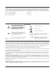
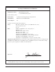


Table Of Contents
- Contents
- Warranty
- U.S. Government Restricted Rights
- WARNINGS
- Declaration of Conformity
- Chapter 1 Installing and Configuring the HP E1459A...
- Functional Description
- Configuring for Installation
- WARNING SHOCK HAZARD. Only qualified, service-trai...
- WARNING SHOCK HAZARD. When handling user wiring co...
- WARNING SHOCK HAZARD. Use wire with an insulation ...
- Caution MAXIMUM VOLTAGE. Maximum allowable voltage...
- Caution STATIC-SENSITIVE DEVICE. Use anti-static p...
- Setting the Logical Address
- Setting the Interrupt Priority
- Note Consult your mainframe manual to be sure that...
- WARNING To prevent electric shock, tighten facepla...
- WARNING To prevent the spread of fire in the case ...
- Chapter 2 Using the HP E1459A Module
- Chapter 3 HP E1459A SCPI Command Reference
- Common Command Format
- SCPI Command Format
- DIAGnostic:SYSReset Subsystem
- DISPlay:MONitor Subsystem
- INPut Subsystem
- MEASure Subsystem
- MEMory Subsystem
- SENSe Subsystem
- DAV
- NEDGe
- PEDGe
- Syntax
- [SENSe:]EVENt:PORTn:DAVailable?
- [SENSe:]EVENt:PORTn:DAVailable:ENABle
- [SENSe:]EVENt:PORTn:DAVailable:ENABle?
- [SENSe:]EVENt:PORTn:EDGE?
- [SENSe:]EVENt:PORTn:EDGE:ENABle
- [SENSe:]EVENt:PORTn:EDGE:ENABle?
- [SENSe:]EVENt:PORTn:NEDGe?
- [SENSe:]EVENt:PORTn:NEDGe:ENABle
- [SENSe:]EVENt:PORTn:NEDGe:ENABle?
- [SENSe:]EVENt:PORTn:PEDGe?
- [SENSe:]EVENt:PORTn:PEDGe:ENABle
- [SENSe:]EVENt:PORTn:PEDGe:ENABle?
- [SENSe:]EVENt:PSUMmary:DAVailable?
- [SENSe:]EVENt:PSUMmary:EDGE?
- STATus Subsystem
- Note Transition filters are always set for positiv...
- Note The Questionable Status Condition, Event, and...
- STATus:OPERation:CONDition?
- STATus:OPERation:ENABle
- STATus:OPERation:ENABle?
- STATus:OPERation[:EVENt]?
- STATus:OPERation:PSUMmary:CONDition?
- STATus:OPERation:PSUMmary:ENABle
- STATus:OPERation:PSUMmary:ENABle?
- STATus:OPERation:PSUMmary[:EVENt]?
- STATus:PRESet
- STATus:QUEStionable:CONDition?
- STATus:QUEStionable:ENABle
- STATus:QUEStionable:ENABle?
- STATus:QUEStionable[:EVENt]?
- SYSTem Subsystem
- IEEE 488.2 Common Commands
- Command Quick Reference
- Appendix A HP E1459A Specifications
- Max Input Voltage: Between High and Low terminal o...
- Module Size/Device Type: C, Register-based.
- Connectors Used: P1 and P2.
- Number of Slots: 1
- VXIbus Interface Capability: Interrupter, D16.
- Interrupt Level: 1-7, selectable.
- Power Requirements: Voltage: +5Vdc Peak Module Cur...
- Watts/Slot: 1.0
- Minimum Pulse Width: 100ms + debounce time.
- Operating Range:
- Debounce: Programmable from 16 mS to 1074 S.
- 5 Volt Supply: Output voltage : 4.5 to 5.5 V DC. M...
- Typical Time to Read 16-bit Word: 4 mS using regis...
- Terminal Module: Screw type, removable, maximum wi...
- Appendix B HP E1459A Register Definitions
- Overview
- Addressing the Registers
- The following commands are sent to the HP E1406 Co...
- When using an embedded controller VXI A16 address ...
- For example, for the HP 75000 Series C Mainframe w...
- base address (h) = (logical addressh)*40h + C000h
- For the HP E1459A, the factory-set logical address...
- base address = (90h)*(40h) + C000h> = E400h
- register address = [A16 location]h + [base addr]h ...
- The following registers can be accessed on the HP ...
- ID register (base = 00h) is a read only register. ...
- * Returns FFFFh = Hewlett-Packard A16 (only) regis...
- Device Type register (base = 02h) is a read only r...
- NOTE: Bits 8 and 9 are returned in the IACK respon...
- WRITE R = Reset to power-on state by writing a "1"...
- READ E IRQ = When "1" it indicates that an INTRX l...
- INTRX = Edge interrupt for port 0 - 3. A "1" means...
- DAVX = Data available in Port 0 - 3. A "1" means t...
- DOGENAB = "0" the watchdog timer is disabled. "1" ...
- DOGSTATE = "0" the watchdog timer is not asserted....
- For reading and writing, when BS = 0 in the Status...
- EDGE ENAB = "1" allows an edge interrupt (INTR for...
- INT/EXT = "0" data will be latched using the inter...
- DAV ENAB = "1" allows the DAV0/2 line to cause an ...
- Channels 0 through 15 are accessed when BS = 0 in ...
- Channels 32 through 47 are accessed when BS = 1 in...
- For Positive/Negative Edge Detect and Mask Registe...
- For Positive/Negative Edge Detect and Mask Registe...
- When BS = 0 in the Status/Control Register, the de...
- When BS = 1 in the Status/Control Register, the de...
- The following table lists the actual values for th...
- Register Value
- Bit pattern (hex)
- Clock Frequency
- Clock Period
- Debounce Time (4 - 4.5 clock periods)
- 2 (or 0, default)
- 0002h
- 250 kHz
- 4 mS
- 16 - 18 mS
- 3 (or 1)
- 0003h
- 125 kHz
- 8 mS
- 32 - 36 mS
- 4
- 0004h
- 62.5 kHz
- 16 mS
- 64 - 72 mS
- 5
- 0005h
- 31.25 kHz
- 32 mS
- 128 - 144 mS
- 6
- 0006h
- 15.63 kHz
- 64 mS
- 256 - 288 mS
- 7
- 0007h
- 7.81 kHz
- 128 mS
- 512 - 576 mS
- 8
- 0008h
- 3.90 kHz
- 256 mS
- 1.0 - 1.13 mS
- 9
- 0009h
- 1.95 kHz
- 512 mS
- 2.0 - 2.26 mS
- 10
- 000Ah
- 976 Hz
- 1 mS
- 4.1 - 4.6 mS
- 11
- 000Bh
- 488 Hz
- 2 mS
- 8.2 - 9.2 mS
- 12
- 000Ch
- 244 Hz
- 4.1 mS
- 16.4 - 18.4 mS
- 13
- 000Dh
- 122 Hz
- 8.2 mS
- 32.8 - 36.9 mS
- 14
- 000Eh
- 61 Hz
- 16.4 mS
- 65.5 - 73.8 mS
- 15
- 000Fh
- 30.5 Hz
- 32.8 mS
- 131 - 148 mS
- 16
- 0010h
- 15.3 Hz
- 65.5 mS
- 262 - 294 mS
- 17
- 0011h
- 7.63 Hz
- 131 mS
- 524 - 59 mS
- 18
- 0012h
- 3.82 Hz
- 262 mS
- 1.05 - 1.16 S
- 19
- 0013h
- 1.91 Hz
- 524 mS
- 2.1 - 2.36 S
- 20
- 0014h
- 0.954 Hz
- 1.05 S
- 4.2 - 4.72 S
- 21
- 0015h
- 0.477 Hz
- 2.1 S
- 8.39 - 9.43 S
- 22
- 0016h
- 0.238 Hz
- 4.2 S
- 16.8 - 18.9 S
- 23
- 0017h
- 0.119 Hz
- 8.39 S
- 33.6 - 37.8 S
- 24
- 0018h
- 60.0 mHz
- 16.8 S
- 67.1 - 75 S
- 25
- 0019h
- 30.0 mHz
- 33.6 S
- 134 - 150 S
- 26
- 001Ah
- 15.0 mHz
- 67.1 S
- 268 - 300 S
- 27
- 001Bh
- 7.5 mHz
- 134 S
- 537 - 600 S
- 28
- 001Ch
- 3.7 mHz
- 268 S
- 1074 - 1200 S
- 29
- 001Dh
- 1.9 mHz
- 537 S
- 2147 - 2400 S
- 30
- 001Eh
- 931 mHz
- 1074 S
- 4295 - 4800 S
- 31
- 001Fh
- 465.5 mHz
- 2148 S
- 8590 - 9600 S
- Command Register Port 1/3
- Command Register Port 1/3 (base + 20h)
- For reading and writing, when BS = 0 in the Status...
- EDGE ENAB = "1" allows an edge interrupt (INTR for...
- INT/EXT = "0" data will be latched using the inter...
- DAV ENAB = "1" allows the DAV1/3 line to cause an ...
- Channels 16 through 31 are accessed when BS = 0 in...
- For Positive/Negative Edge Detect and Mask Registe...
- For Positive/Negative Edge Detect and Mask Registe...
- When BS = 0 in the Status/Control Register, the de...
- Register Value
- Bit Pattern (Hex)
- Clock Frequency
- Clock Period
- Debounce Time (4 - 4.5 Clock Periods)
- 2 (or 0 ) Default
- 0002h
- 250 kHz
- 4 mS
- 16 - 18 mS
- 3 (or 1)
- 0003h
- 125 kHz
- 8 mS
- 32 - 36 mS
- 4
- 0004h
- 62.5 kHz
- 16 mS
- 64 - 72 mS
- 5
- 0005h
- 31.25 kHz
- 32 mS
- 128 - 144 mS
- 6
- 0006h
- 15.63 kHz
- 64 mS
- 256 - 288 mS
- 7
- 0007h
- 7.81 kHz
- 128 mS
- 512 - 576 mS
- 8
- 0008h
- 3.90 kHz
- 256 mS
- 1.0 - 1.13 mS
- 9
- 0009h
- 1.95 kHz
- 512 mS
- 2.0 - 2.26 mS
- 10
- 000Ah
- 976 Hz
- 1 mS
- 4.1 - 4.6 mS
- 11
- 000Bh
- 488 Hz
- 2 mS
- 8.2 - 9.2 mS
- 12
- 000Ch
- 244 Hz
- 4.1 mS
- 16.4 - 18.4 mS
- 13
- 000Dh
- 122 Hz
- 8.2 mS
- 32.8 - 36.9 mS
- 14
- 000Eh
- 61 Hz
- 16.4 mS
- 65.5 - 73.8 mS
- 15
- 000Fh
- 30.5 Hz
- 32.8 mS
- 131 - 148 mS
- 16
- 0010h
- 15.3 Hz
- 65.5 mS
- 262 - 294 mS
- 17
- 0011h
- 7.63 Hz
- 131 mS
- 524 - 590 mS
- 18
- 0012h
- 3.82 Hz
- 262 mS
- 1.05 - 1.18 S
- 19
- 0013h
- 1.91 Hz
- 524 mS
- 2.1 - 2.36 S
- 20
- 0014h
- 0.954 Hz
- 1.05 S
- 4.2 - 4.72 S
- 21
- 0015h
- 0.477 Hz
- 2.1 S
- 8.39 - 9.43 S
- 22
- 0016h
- 0.238 Hz
- 4.2 S
- 16.8 - 18.9 S
- 23
- 0017h
- 0.119 Hz
- 8.39 S
- 33.6 - 37.8 S
- 24
- 0018h
- 60 mHz
- 16.8 S
- 67.1 - 75 S
- 25
- 0019h
- 30 mHz
- 33.6 S
- 134 - 150 S
- 26
- 001Ah
- 15 mHz
- 67.1 S
- 268 - 300 S
- 27
- 001Bh
- 7.5 mHz
- 134 S
- 537 - 600 S
- 28
- 001Ch
- 3.7 mHz
- 268 S
- 1074 - 1200 S
- 29
- 001Dh
- 1.9 mHz
- 537 S
- 2147 - 2400 S
- 30
- 001Eh
- 931 mHz
- 1074 S
- 4295 - 4800 S
- 31
- 001Fh
- 466 mHz
- 2147 s
- 8590 - 9600 s
- Power On/Reset Conditions
- Programming Examples
- Appendix C Error Messages
- Index

6
Safety Symbols
Instruction manual symbol affixed to
product. Indicates that the user must refer to
the manual for specific WARNING or
CAUTION information to avoid personal
injury or damage to the product.
Alternating current (AC)
Instruction manual symbol affixed to
product. Indicates that the user must refer to
the manual for specific WARNING or
CAUTION information to avoid personal
injury or damage to the product.
Indicates the field wiring terminal that must
be connected to earth ground before
operating the equipment — protects against
electrical shock in case of fault.
Direct current (DC).
Indicates hazardous voltages.
or
Frame or chassis ground terminal—typically
connects to the equipment's metal frame.
WARNING
Calls attention to a procedure, practice, or
condition that could cause bodily injury or
death.
CAUTION
Calls attention to a procedure, practice, or
condition that could possibly cause damage to
equipment or permanent loss of data.
WARNINGS
The following general safety precautions must be observed during all phases of operation, service, and repair of this product. Failure to
comply with these precautions or with specific warnings elsewhere in this manual violates safety standards of design, manufacture, and
intended use of the product. Hewlett-Packard Company assumes no liability for the customer's failure to comply with these requirements.
Ground the equipment: For Safety Class 1 equipment (equipment having a protective earth terminal), an uninterruptible safety earth
ground must be provided from the mains power source to the product input wiring terminals or supplied power cable.
DO NOT operate the product in an explosive atmosphere or in the presence of flammable gases or fumes.
For continued protection against fire, replace the line fuse(s) only with fuse(s) of the same voltage and current rating and type. DO NOT
use repaired fuses or short-circuited fuse holders.
Keep away from live circuits: Operating personnel must not remove equipment covers or shields. Procedures involving the removal of
covers or shields are for use by service-trained personnel only. Under certain conditions, dangerous voltages may exist even with the
equipment switched off. To avoid dangerous electrical shock, DO NOT perform procedures involving cover or shield removal unless you
are qualified to do so.
DO NOT operate damaged equipment: Whenever it is possible that the safety protection features built into this product have been
impaired, either through physical damage, excessive moisture, or any other reason, REMOVE POWER and do not use the product until
safe operation can be verified by service-trained personnel. If necessary, return the product to a Hewlett-Packard Sales and Service Office
for service and repair to ensure that safety features are maintained.
DO NOT service or adjust alone: Do not attempt internal service or adjustment unless another person, capable of rendering first aid and
resuscitation, is present.
DO NOT substitute parts or modify equipment: Because of the danger of introducing additional hazards, do not install substitute parts
or perform any unauthorized modification to the product. Return the product to a Hewlett-Packard Sales and Service Office for service
and repair to ensure that safety features are maintained.
Documentation History
All Editions and Updates of this manual and their creation date are listed below. The first Edition of the manual is Edition 1. The Edition
number increments by 1 whenever the manual is revised. Updates, which are issued between Editions, contain replacement pages to
correct or add additional information to the current Edition of the manual. Whenever a new Edition is created, it will contain all of the
Update information for the previous Edition. Each new Edition or Update also includes a revised copy of this documentation history page.
Edition 1 (as HP Z2404-90000). . . . . . . . . . . . . . . . . . . . . . . . . . . . August 1991
Edition 2 (as HP Z2404-90001). . . . . . . . . . . . . . . . . . . . . . . . . . . February 1996
Edition 3 (HP E1459-90001). . . . . . . . . . . . . . . . . . . . . . . . . . . . . . . . . July 1997