Instructions/Parts List ELECTROSTATIC, WATERBORNE, AIR SPRAY WB100 Isolation System and PRO™ Xs3 Spray Gun 309293J Important Safety Instructions Read all warnings and instructions in this manual. Save these instructions. 100 psi (0.7 MPa, 7 bar) Maximum Air Inlet Pressure 100 psi (0.
Table of Contents List of Models . . . . . . . . . . . . . . . . . . . . . . . . . . . . . 3 Symbols . . . . . . . . . . . . . . . . . . . . . . . . . . . . . . . . . . 4 Warning Symbol . . . . . . . . . . . . . . . . . . . . . . . . . 4 Caution Symbol . . . . . . . . . . . . . . . . . . . . . . . . . . 4 Warning . . . . . . . . . . . . . . . . . . . . . . . . . . . . . . . . . . 4 Introduction . . . . . . . . . . . . . . . . . . . . . . . . . . . . . . . 7 How the Electrostatic Air Spray Gun Works . . . .
List of Models List of Models FM Approved Part No. Gun Model Description 245897 PRO Xs3 Waterborne Isolation Enclosure with standard electrostatic air spray gun, grounded air hose, and shielded waterborne fluid hose 245898 PRO Xs3 Waterborne Isolation Enclosure with smart electrostatic air spray gun, grounded air hose, and shielded waterborne fluid hose 233825 Waterborne Isolation Enclosure without hoses and gun.
Symbols Symbols Warning Symbol Caution Symbol WARNING CAUTION This symbol alerts you to the possibility of serious injury or death if you do not follow the instructions. This symbol alerts you to the possibility of damage to or destruction of equipment if you do not follow the instructions. WARNING Electric Shock Hazard Improper grounding, setup, or usage of an isolated waterborne system can cause a hazardous condition and result in electric shock or other serious injury.
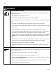
Warning WARNING Fire and Explosion Hazard Improper grounding, poor air ventilation, open flames, or sparks can cause a hazardous condition and result in a fire or explosion. • Electrostatic equipment must be used only by trained, qualified personnel who understand the requirements in this manual. • Ground the equipment, all personnel in or close to the spray area, the object being sprayed, and all other electrically conductive objects in the spray area. See Grounding, page 17.
Warning WARNING Equipment Misuse Hazard Equipment misuse can cause the equipment to rupture, malfunction, or start unexpectedly and result in a serious injury. • This equipment is for professional use only. • Read all manuals, tags, and labels before operating the equipment. • Use the equipment only for its intended purpose. If you are uncertain, call your Graco distributor. • Do not alter or modify equipment. Use only genuine Graco parts and accessories.
Introduction Introduction How the Electrostatic Air Spray Gun Works The air hose supplies air to the spray gun. Part of the air operates the turbine and the rest of the air atomizes the fluid being sprayed. The turbine generates power, which is converted by the power cartridge to supply high voltage current to the gun’s electrode. The fluid source supplies fluid to the hose and gun. The gun must be connected to a voltage isolation system to maintain voltage at the gun.
Introduction Gun Overview • ES ON/OFF valve. Turns electrostatics ON (I) or OFF (0). The electrostatic gun includes the following controls (see FIG. 1.). • ES INDICATOR (standard gun only). Green when ES is ON (I). • Voltage/current DISPLAY (smart models only). Shows voltage (V) and current (A). Green=spray, yellow/red=see Electrical Troubleshooting, page 39. • ES HI/LO switch (smart models only). Sets voltage to HI or LO (factory settings). • LO VOLTAGE adjustment (smart models only).
Installation Installation System Requirements Warning Sign A safe, well designed voltage isolation system should have the following features: Mount the warning sign, Part No. 186118, in the spray area where it can be seen and read by all operators. Additional warning signs are available at no charge.
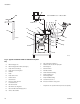
Installation B* Gun ES ON/OFF valve: I is ON, 0 is OFF BB Q* M C A D E U S B* K* AA P* L X N G TI1896C R W J V* Y Z F T H TI1775C Fig. 2.
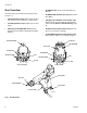
Installation Ventilate the Spray Booth 4. Connect the main air supply line (A) to the bleed-type air valve (B). The bleed valve shuts off all air to the system. Install an additional bleed-type air valve (B) upstream of the air filter (M) to isolate the filter for servicing. WARNING Flammable or Toxic Vapor Hazard Provide fresh air ventilation to avoid the buildup of flammable or toxic vapors. Do not operate the gun unless ventilation fans are operating.
Installation 1. Remove the gun air inlet fitting (35). See FIG. 3.. Shielded Hose 245252 C T F A A 16 J B A 7.40 in. (188 mm) B 2.0 in. (50 mm) 104 108 Fig. 4. Waterborne Hose Dimensions (At Gun) 107 106 35 105 103 102 Unshielded Hose 246431 38 39 TI2155A 101 Fig. 3. Connect the Fluid Hose In a shielded hose system, if a hose failure occurs where high voltage arcs through the inner tube, voltage will be discharged to ground through the conductive hose layer.
Installation a. Graco WB100 Enclosure: Slide hose through the strain relief fitting (W). Ensure conductive layer (C) has passed through fitting. Tighten to 55 in-lb (6.2 N•m). Pull back on hose to check it is secure. Comply with the requirements in Warning at right. See FIG. 6. and FIG. 7.. W J T C Shielded Hose 245252 C See Warning below. T J Z B A L A 14.5 in. (368 mm) B 0.75 in. (19 mm) TI2744A Fig. 9. Unshielded fluid connection TI2166A Fig. 6.
Installation c. Connect the end of the tube (T) to the pump fluid outlet fitting (Z). 7. Assemble the other parts of the kit as shown. Secure the agitator with the setscrew (408). 8. Return the system to service. CAUTION The Graco warranty is void if the spray gun is connected to a non-Graco voltage isolation system or if the gun is operated above 60 kV.
Installation 245944 Fluid Regulator Kit To add a fluid regulator to the Graco isolation system, order Part No. 245944. See page 68 for the kit parts list. 12. Connect tube (A1) to the air inlet of fluid regulator (504). Connect tube (507) to the pump air inlet. 13. Connect the waterborne fluid hose to the fluid regulator outlet fitting (501). 1. Discharge the system voltage (page 20). 2. Relieve the pressure (page 20). 3. Open the isolated enclosure door. 4.
Installation Select a Fluid Nozzle and Air Cap WARNING Table 1: Fluid Nozzles Part No. Size, mm (in.) Part No. Size, mm (in.) 197263 0.75 (.030) 197266 1.5 (.055) 197264 1.0 (.042) 197267 1.8 (.070) 197265 1.2 (.047) 197268 2.0 (.080) Pressurized Equipment Hazard To reduce the risk of an injury, follow the Pressure Relief Procedure on page 20 before removing or installing a fluid nozzle and/or air cap. The gun is supplied with Part No. 197266 Nozzle and 197477 Air Cap.
Installation Grounding • Voltage Isolation System: electrically connect to a true earth ground, as instructed in the voltage isolation system manual. • Object being sprayed: keep the workpiece hangers clean and grounded at all times. Resistance must not exceed 1 megohm. • The floor of the spray area: must be electrically conductive and grounded. Do not cover the floor with cardboard or any non-conductive material which would interrupt grounding continuity.
Installation Check Electrical Grounding BB 1. Have a qualified electrician check the electrical grounding continuity of the spray gun and air hose. 2. Turn the ES ON/OFF valve OFF. I ES O ti1273a AA 3. Turn off the air and fluid supply to the gun. The fluid hose must not have any fluid in it. 4. Make sure the red-colored grounded air hose (R) is connected and the hose ground wire is connected to a true earth ground. CC TI2161A Fig. 13. Check Gun Grounding 7.
Operation Operation Operating Checklist Check the following list daily, before starting to operate the system, to help ensure you of safe, efficient operation. Ventilation fans are operating properly. All operators are properly trained to safely operate an electrostatic waterborne air spray system as instructed in this manual. All operators are trained in the Pressure Relief Procedure on page 20. The electrostatics are turned off and properly grounded according to the.
Operation Fluid Voltage Discharge and Grounding Procedure Pressure Relief Procedure WARNING WARNING Pressurized Equipment Hazard Electric Shock Hazard The fluid supply is charged with high voltage until the voltage is discharged. Contact with the charged components of the isolation system or spray gun electrode will cause an electric shock.
Operation Fill the Fluid Supply 1. Discharge the system voltage (page 20). WARNING 2. Relieve the pressure (page 20). Fire and Explosion Hazard To reduce the risk of fire and explosion, only use this equipment with fluids that meet at least one of the following conditions for non-flammability:. ti1276a 3. Open the isolated enclosure door. 4. Remove the pail cover from the pail, holding a rag over the suction tube strainer to prevent any fluid from dripping into the isolated enclosure.
Operation 4. Fully open the fan air adjustment valve. WARNING 0 KV 100% μα HI LO Pressurized Equipment Hazard ES ES I To reduce the risk of an injury, follow the Pressure Relief Procedure on page 20 whenever you are instructed to relieve the pressure. O ti1269a 1. Make sure the ES ON/OFF valve is OFF. 5. Fully open the fluid adjustment valve. I ES O 0 KV 100% μα HI LO ES ti1273a ES I O 2. Turn on the main air supply valve (B). ti1267a 6.
Operation 8. Adjust the pump air regulator to start the fluid supply unit. Adjust the fluid flow with the air pressure regulator until the stream from the gun travels 8-12 in. (200-300 mm) before falling off. Typically, if fluid pressure is below 5 psi (.04 MPa, 0.4 bar) or above 20 psi (0.14 MPa, 1.4 bar), a change of nozzle size is recommended. Refer to instruction manual 309419 to set the fluid pressure for various fluid flows, according to the size of the fluid nozzle being used. 10.
Operation 13. Check that the ES indicator or display is lit, or check that the kV indicator on the isolated enclosure reads 45-55 kV. If not, see Electrical Troubleshooting on page 39 for possible problems. 0 KV 15. Spray a test piece. Examine the edges for coverage. If wrap is poor, see Spray Pattern Troubleshooting on page 37. 100% μα HI I ES O LO ES I ES O ti1266a ti1253a 14. Check the kV meter on the isolated enclosure; 45-55 kV is normal. ti1285a 16.
Operation Shutdown Low Voltage Adjustment (Smart Guns Only) 1. Discharge the system voltage (page 20). The ES HI/LO switch enables you to switch between full voltage and a lower voltage output. The lower voltage is factory set, but can be adjusted. 2. Flush the spray gun. See page 26. 1. Set the ES HI/LO switch to LO. ti1276a 2. Remove the LO VOLTAGE adjustment plug (53). Set the desired voltage, using a small screwdriver to slide switches 1 and 2 ON or OFF, according to Table 4 . Also see FIG. 15..
Maintenance Maintenance Flush the Spray Gun 1. Turn the ES ON/OFF valve OFF and wait 30 seconds for the voltage to bleed off. Flush the gun before changing colors, at the end of the day, before storing, and before repairing the gun. I ES O ti1273a WARNING Fire, Explosion, and Electric Shock Hazard 2. Discharge the system voltage (page 20). 3. Relieve the pressure (page 20). To reduce the risk of fire, explosion, or electric shock, turn the ES ON/OFF valve OFF before flushing the gun.
Maintenance Daily Care and Cleaning CAUTION • Clean the outside of the gun daily with a soft cloth dampened with a non-flammable solvent, as defined on page 26. • Check for fluid leaks. Tighten all fittings. • Clean the air cap and fluid nozzle daily, minimum. See page 29. Some applications require more frequent cleaning. • Fluid in the air passages could cause the gun to malfunction and could draw current and reduce the electrostatic effect.
Maintenance CAUTION • Inspect the cabinet and clean up any spilled paint. Conductive paint residue allowed to contact grounded parts may short out the electrostatics. • Keep the inside of the cabinet clean, for proper operation. • Visually inspect the ground strip (240) for damage. Replace if needed. Measure the resistance weekly. See page 33.
Maintenance Clean the Air Cap and Fluid Nozzle 5. Clean the air cap (9) with the soft bristle brush and non-flammable solvent or submerge the air cap in solvent and wipe it clean. Equipment Needed 6. With the gun pointing down, clean the fluid nozzle (7) and the front of the gun with a soft brush dampened with non-flammable solvent. If it appears that there is paint inside the fluid nozzle (7) air passages, remove the gun from the line for servicing.
Electrical Tests Electrical Tests Electrical components inside the gun affect performance and safety. The following procedures test the condition of the power supply (18) and electrode (29), and electrical continuity between components. Use megohmmeter Part No. 241079 (AA) and an applied voltage of 500 V. Connect the leads as shown. WARNING Test Gun Resistance 1. Prepare the gun for service as instructed on page 41. 2.
Electrical Tests Test Power Supply Resistance 1. Prepare the gun for service as instructed on page 41. 2. Remove the power supply (18), page 46. 3. Remove the turbine alternator (19) from the power supply, page 47. 4. Measure resistance from the power supply's ground strips (EE) to the spring (18b). See FIG. 18.. 18b 5. The resistance should be 95-105 megohms. If outside this range, replace the power supply. If in range, proceed to the next test. EE ti1599a Fig. 18. Test Power Supply Resistance 6.
Electrical Tests Test Electrode Resistance 1. Prepare the gun for service as instructed on page 41. 2. Insert a conductive rod (B) into the gun barrel (removed for the power supply test) and against the metal contact (C) in the front of the barrel. 3. Measure the resistance between the conductive rod (B) and the electrode (29). The resistance should be 20-30 megohms. See FIG. 19.. F 29 E ti1548a 4.
Electrical Tests Test Ground Strip Resistance Test Cylinder Resistance See FIG. 22.. Using an ohmmeter, measure the resistance between the latch housing (206) and the ground lug (214). The ground strip is grounded through the cart back to the ground lug. Resistance must be less than 100 ohms. If greater than 100 ohms, replace the ground strip (240). See FIG. 23.. Remove the enclosure door. Using an ohmmeter, measure the resistance from the pump (209) to the ground lug (214).
Troubleshooting Troubleshooting WARNING Electric Shock Hazard Installing and servicing this equipment requires access to parts which may cause an electric shock or other serious injury if the work is not performed properly. Do not install or repair this equipment unless you are trained and qualified. Follow the Fluid Voltage Discharge and Grounding Procedure on page 20 before checking or servicing the system and whenever you are instructed to discharge the voltage.
Troubleshooting Visual Check First, check the system for any visible faults or errors to help isolate whether the spray gun, fluid hose or voltage isolation system has failed. A voltage probe and meter, part no. 236003, is helpful for diagnosing voltage problems and is required for some of the troubleshooting tests that follow. 1. Check that all of the air and fluid tubes and hoses are properly connected. 2. Check that the voltage isolation system valves and controls are properly set for operation. 3.
Troubleshooting 9. Flush the fluid hose and gun with enough air to dry out the fluid passages. Inspect the end of the hose connected to the voltage isolation system. Look for cuts or nicks. 10. Turn the ES ON/OFF valve to ON and trigger the gun. Measure the voltage at the gun electrode with a voltage probe and meter. • Make sure the hose is properly stripped (see step 2 on page 12). Restrip or replace the hose.
Troubleshooting Spray Pattern Troubleshooting Check all possible remedies in the Troubleshooting Chart before disassembling the gun. Some spray pattern problems are caused by the improper balance between air and fluid. Problem Cause Solution Fluttering or spitting spray. No fluid. Refill supply. Loose, dirty, damaged nozzle/seat. Clean or replace nozzle, page 42. Air in fluid supply. Check fluid source. Refill. Damaged nozzle or air cap. Replace, page 42. Fluid buildup on air cap or nozzle.
Troubleshooting Gun Operation Troubleshooting Problem Cause Solution Excessive spray fog. Atomizing air pressure too high. Close restrictor valve some, or decrease air pressure as low as possible; minimum 40 psi (0.28 MPa, 2.8 bar) needed at gun for full voltage. Fluid too thin. Increase viscosity. Atomizing air pressure too low. Open atomizing air valve more or increase gun air inlet pressure; use lowest air pressure necessary. “Orange Peel” finish. Poorly mixed or filtered fluid.
Troubleshooting Electrical Troubleshooting Problem Cause Voltage still present at gun after following the Fluid Voltage Discharge and Grounding Procedure ES ON/OFF valve is not turned OFF. Turn OFF. Poor wrap. 309293J Solution Did not wait long enough for voltage to discharge. Wait longer before touching electrode with grounded rod. Check for bleed resistor failure. Air pocket in fluid line leaves fluid near gun isolated. Determine cause and correct. Purge air from fluid line.
Troubleshooting Problem Cause Solution ES indicator or voltage/current display is not lit. ES ON/OFF valve OFF (0).* Turn ON (I). No power. Replace power supply. See page 47. Gun too close to part. Should be 8-12 in. (200-300 mm). Check fluid resistivity. See Operation on page 19. Voltage/current display stays red (smart guns only). Operator gets mild shock. Dirty gun. Clean. See page 27. Operator not grounded or is near ungrounded object. See Grounding on page 17. Gun not grounded.
Repair Repair Prepare the Gun for Service • Check all possible remedies in Troubleshooting before disassembling the gun. • Use a vise with padded jaws to prevent damage to plastic parts. • Lubricate the power supply o-ring (18a), some packing rod parts (26), and certain fluid fittings with dielectric grease (40), as specified in the text. • Lightly lubricate o-rings and seals with non-silicone grease. Order Part No. 111265 Lubricant. Do not over-lubricate. • Only use genuine Graco parts.
Repair Air Cap/Nozzle Replacement WARNING CAUTION Fire, Explosion, and Electric Shock Hazard Hold the front end of the gun up and trigger the gun while removing the nozzle to help drain the gun and prevent any paint or solvent left in the gun from entering the air passages. 1. Prepare gun for service, page 41. 2. Remove the retaining ring (27) and air cap (9). See FIG. 24.. 3. Point gun up and squeeze trigger while removing the fluid nozzle (7) assembly with the multi-tool (37).
Repair Electrode Replacement 1. Prepare the gun for service, page 41. 2. Remove the air cap and nozzle, page 42. 3. Unscrew the electrode (29) with the multi-tool (37). Hold the packing rod end (26h) to prevent it from turning, FIG. 25.. 37 CAUTION To avoid damaging the plastic threads, be very careful when installing the electrode. 4. Apply low-strength (purple) Loctite® or equivalent thread sealant to the electrode and packing rod threads. Install the electrode finger-tight. Do not overtighten.
Repair Fluid Packing Removal 1. Prepare the gun for service, page 41. 2. Remove the air cap and fluid nozzle, page 42. 3. Remove the electrode, page 43. 4. Loosen the trigger screws (8) and trigger (30). See FIG. 26.. 5. Remove the packing rod (26), using the multi-tool (37). 37 30 CAUTION 8 Clean all parts in non-conductive solvent compatible with the fluid being used, such as xylol or mineral spirits. Use of conductive solvents can cause the gun to malfunction. TI1683A 6.
Repair Packing Rod Repair You may replace the packing rod as individual parts or as an assembly. The assembly is pre-adjusted at the factory. 4. Lightly tighten the packing nut (26e). The packing nut is properly tightened when there is 3 lb (13.3 N) of drag force when sliding the packing housing (26f) assembly along the rod. Tighten or loosen the packing nut as needed. Before installing the fluid packing rod into the gun barrel, make sure the internal surfaces of the barrel are clean.
Repair Barrel Removal 5. Apply dielectric grease (40) to the exposed inner tube of the fluid hose (101). 1. Prepare the gun for service, page 41. 6. Check that the nut (105) is tight on the ferrule housing (103). 2. Remove the air inlet fitting (35) and take the bracket (104) off the gun handle (17). 7. Test gun resistance, page 30. 3. Loosen the three screws (11). 104 CAUTION 11 16 To avoid damaging the power supply (18), pull the gun barrel straight away from the gun handle.
Repair Power Supply Removal and Replacement • • Inspect the gun handle power supply cavity for dirt or moisture. Clean with a clean, dry rag. Do not expose gasket (10) to solvents. 1. Prepare gun for service, page 41. 2. Remove the barrel (16), page 46. 8. Lubricate the alternator o-ring (19a*) with non-silicone grease, Part No. 111265. Do not over-lubricate. 9. Lubricate the power supply o-ring (18a*) with dielectric grease (40). 10. Insert the power supply/alternator assembly in the gun handle (17).
Repair Turbine Alternator Removal and Replacement Replace turbine alternator bearings after 2000 hours of operation. Order Part No. 223688 Bearing Kit. 1. Prepare gun for service, page 41. 2. Remove the power supply/alternator assembly, page 47. 3. Disconnect the alternator from the power supply, page 47. 48 4. Measure resistance between the two outer terminals of the 3-wire connector (GG); it should be 2.5-3.5 ohms. If outside this range, replace the alternator coil. 5.
Repair Fan Air Adjustment Valve Repair 1. Prepare the gun for service, page 41. 2. Place a wrench on the flats of the valve assembly (20) and unscrew it from the handle (17). You may replace the valve as an assembly (go to step 9) or as individual parts (steps 3-9). 3. Remove the retaining ring (20a). See FIG. 31.. 4. Turn the valve stem (20d) counterclockwise until it comes free from the valve housing (20c). 6. Clean all parts and inspect for wear or damage. Use non-silicone grease, Part No. 111265.
Repair Fluid Adjustment Valve Repair 1. Prepare the gun for service, page 41. 4. Remove the air valve (21 ) with a pliers. Inspect the seal (21a*) and replace if damaged. Be sure the seal is pressed securely onto the valve so the outer cone is flats. 2. Remove the fluid adjustment valve (25). It can only be replaced as a complete assembly. See FIG. 32.. 3. Screw the valve (25) into the gun handle. Torque to 15-25 in-lb (1.7-2.8 N•m).
Repair Atomizing Air Restrictor Valve Removal and Replacement 1. Prepare the gun for service, page 41. 2. Loosen the screw (48). Remove the valve. 3. Lubricate the o-rings (22a* and 22b*) with non-silicone grease, Part No. 111265. Do not over-lubricate. 2. Remove the atomizing air restrictor valve (23). Inspect the o-ring (23c*). Replace if necessary. See FIG. 34.. 3. Install a new atomizing air restrictor valve (23), or disassemble and replace parts individually.
Parts Parts Part No. 244581 60 kV Electrostatic Gun, Series B (items 4-55) Part No. 245301 60 kV Electrostatic Gun with Shielded waterborne fluid hose, Series A (items 4-55, 101-108) See page 53 for detail views of the alternator (19), fan adjustment valve (20), ES ON/OFF valve (22), and packing rod (26).
Parts Ref. No. 19: Alternator Ref. No. 20: Fan Adjustment Valve 20d 19a* 19b TI1487A 20b* 20c 19b 20a TI1481a 19e 19d 19c Ref. No. 26: Packing Rod Ref. No.
Parts Part No. 244581 60 kV Electrostatic Gun, Series B (items 4-55) Part No. 245301 60 kV Electrostatic Gun with waterborne fluid hose, Series A (items 4-55, 101-108) Ref. No. Part No. Description 4 185111 SPRING, compression 1 6* 188749 PACKING, u-cup, air valve; uhmwpe 1 NOZZLE; 1.5 mm orifice; includes 7a and 7b 1 7 197266 Qty Ref. No. Part No. Description 20d 197567 .
Parts Ref. No. Part No. Description 27a* 198307 .
Parts Part No. 244582 60 kV Electrostatic Gun, Series B (items 4-59) Part No. 245305 60 kV Electrostatic Gun with waterborne fluid hose, Series A (items 4-59, 101-108) See page 57 for detail views of the alternator (19), fan adjustment valve (20), ES ON/OFF valve (22), and packing rod (26).
Parts Ref. No. 19: Alternator Ref. No. 20: Fan Adjustment Valve 19a* 20d 19b TI1487A 20b* 20c 19b TI1481a 20a 19e 19d 19c Ref. No. 22: ES ON/OFF Valve 22e Ref. No.
Parts Part No. 244582 60 kV Electrostatic Gun, Series B (items 4-59) Part No. 245305 60 kV Electrostatic Gun with waterborne fluid hose, Series A (items 4-59, 101-108) 58 Ref. No. Part No. Description 4 185111 SPRING, compression 1 6* 188749 PACKING, u-cup, air valve; uhmwpe 1 Qty Ref. No. Part No. Description 20b* 106560 . O-RING; fluorocarbon 1 20c 197566 . HOUSING, fan valve 1 20d 197567 . STEM, fan valve 1 21 244557 VALVE, air; includes item 21a 1 21a* 276733 .
Parts Ref. No. Part No. Description 1 53 276734 PLUG, LO voltage adjustment 1 . SPACER, packing; acetal 1 54 197910 SCREW, pivot 1 244696 . ROD, packing 1 55 197624 SPRING, grounding 1 27 245790 RING, retaining, air cap; includes item 27a 1 59 245265 CIRCUIT, flexible 1 101 245252 HOSE, shielded waterborne fluid; 1 27a* 198307 .
Parts Part No. 245897 Isolation Enclosure, Series A, with air and wb fluid hose, standard Xs3 gun (items 201-301) Part No. 245898 Isolation Enclosure, Series A, with air and wb fluid hoses, smart Xs3 gun (items 201-301) Part No. 233825 Isolation Enclosure, Series A, for shielded hoses without hoses and gun (items 201-286) Part No.
Parts Part No. 245897 Isolation Enclosure, Series A, with air and wb fluid hose, standard Xs3 gun (items 201-301) Part No. 245898 Isolation Enclosure, Series A, with air and wb fluid hoses, smart Xs3 gun (items 201-301) Part No. 233825 Isolation Enclosure, Series A, for shielded hoses without hoses and gun (items 201-286) Ref. No. Part No. Description Part No. Description 224 154636 WASHER, plain; 0.625 in.
Parts Ref. No. Part No. 253 Description Qty Ref. No. Part No. Description Qty NUT, hex; 10-32 1 276 15A780 PLUG, hex hd 1 256 162449 NIPPLE, reducing; 1/2 npt x 1/4 npt 2 278 117314 BULKHEAD CONNECTOR; 1/4 npt 1 257 101874 TERMINAL, ring 5 279 113319 2 258 116990 BOX, control 1 CONNECTOR, tube; 1/4 npt x 3/8 in. (10 mm) OD tube 259 113983 RING, retaining; 1/2 in. (13 mm) 1 280 ELBOW, tube 1 260 237933 METER, 0-90 kV 1 281 FITTING, tube; 1/8 npt x 5/32 in.
Parts Tubing and Wiring Chart Use the diagrams on page 64 to find the connection points for the tubing and wiring listed below. Code C2 C3 A1 A2 Ref. No. 248 248 B2 249 B3 B4 249 249 B5 249 C1 272 Code 309293J Length Description in.
Parts Tubing and Wiring Diagrams Detail of Control Box C9 A1 A2 C1 B4 B3 C2, C9 C3, C4, C5 B5 A2 B2 E1 TI2145A C2 B3 Detail of Door Interlock Switch C8 C1 A1 C6, C7, C8 B5 C6 TI2144A B2 C3 TI2143A 64 309293J
Accessories Accessories Air Line Accessories Air Hose Adapter Nipple 185493 Grounded Air Hose (Red Cover) 100 psi (7 bar, 0.7 MPa) Maximum Working Pressure 0.315 in. (8 mm) ID; 1/4 npsm(f) x 1/4 npsm(f) left-hand thread; red cover with stainless steel braid ground path. Use to connect multiple air hoses. 1/4 npt x 1/4 npsm left-hand thread. Non-Swivel Air Inlet Fitting 185105 Replaces standard swivel. Left-hand thread.
Accessories Gun Accessories Cleaning Brush 105749 For cleaning air cap and fluid nozzle. Gun Repair Kits 244781 244911 Air Seal Repair Kit Fluid Seal Repair Kit Round Pattern Kits Consists of fluid tip, diffuser and air cap. 245217 245219 For quick change of fan size. Handle Grips 245263 245264 Medium Grip Large Grip Gun Valve Lubricant 111265 4 oz (113 g) tube of sanitary (non-silicone) lubricant for fluid seals and wear areas.
Accessories Part No. 245895 Agitator Accessory Kit (items 401-407) 407 402 401 406 Ref. No. Part No. Description 401 112698 ELBOW, swivel, male; 1/8 npt(m) x 1/4 in. (6 mm) OD tube 1 402 114158 FITTING, adapter, Y; 1/4 in. (6 mm) OD tube; mxfxf 1 403 193315 COLLAR, mounting, agitator 1 404 193316 NUT, collar, agitator 1 405 197298 COVER, pail; 5 gal. (19 liter) 1 406 224571 AGITATOR; see manual 306565 1 407 purchase locally TUBE; nylon; 1/4 in. (6 mm) OD; 4 ft (1.
Accessories Part No. 245944 Fluid Regulator Accessory Kit (items 501-507) 501 506 507 504 502 505 Ref. No. Part No. Description 501 110078 FITTING, tube, fluid; 1/4 npt(m) x 3/8 in. (10 mm) OD tube 1 502 113070 NIPPLE, reducer; 3/8 npt x 1/4 npt 1 503 113576 PLUG; 1/4 npt 1 504 236281 REGULATOR, fluid; see manual 308325 1 505 C20350 ELBOW, 90°; 1/4 npt(f) x 1/4 in. (6 mm) OD tube 1 506 114158 FITTING, adapter, Y; 1/4 in.
Technical Data Technical Data Category Maximum Working Fluid Pressure Maximum Working Air Pressure Minimum Air Pressure at Gun Inlet Maximum Fluid Operating Temperature Short Circuit Current Output Voltage Output Energy Sound Power (measured per ISO Standard 9216) Sound Pressure (measured 1 m from gun) Gun Air Inlet Fitting, left-hand thread Gun Fluid Inlet Fitting Gun Weight Gun Length Isolation Enclosure Air Inlet Fitting Isolation Enclosure Fluid Inlet Fitting Isolation Enclosure Weight Isolation Enclo
Graco Standard Warranty Graco warrants all equipment manufactured by Graco and bearing its name to be free from defects in material and workmanship on the date of sale to the original purchaser for use. With the exception of any special, extended, or limited warranty published by Graco, Graco will, for a period of twelve months or two thousand hours of operation from the date of sale, repair or replace any part of the equipment determined by Graco to be defective.