
- Hewlett-Packard IP Console Switch User Guide
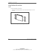
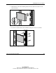
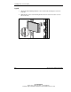
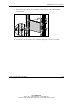
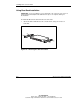

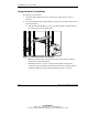
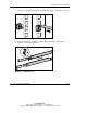

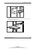
Table Of Contents
- HP IP Console Switch User Guide
- Notice
- Contents
- About This Guide
- Chapter 1: Overview
- Chapter 2: Installing the IP Console Switch
- Chapter 3: Expansion Module
- Chapter 4: Interface Adapters
- Chapter 5: Cascade Console Switches
- Chapter 6: Local Port Operation
- Viewing and Selecting Ports and Servers
- Soft Switching
- Using Basic OSD Navigation
- Configuring the OSD Setup Menu
- Assigning Server Names
- Assigning Device Types
- Changing the Display Behavior
- Controlling the Status Flag
- Broadcasting to Servers
- Setting up a Scan Pattern
- Setting Local Console Switch Security
- Managing Server Tasks Using the OSD
- Viewing and Disconnecting User Connections
- Running System Diagnostics
- Resetting the PS/2 Mouse
- Displaying Version Information
- Chapter 7: Upgrading Firmware using TFTP
- Chapter 8: Troubleshooting
- Appendix A: Regulatory Compliance Notices
- Appendix B: Electrostatic Discharge
- Appendix C: Power Cord Set Requirements
- Index
Installing the IP Console Switch
2-10 HP IP Console Switch User Guide
HP CONFIDENTIAL
Writer: Amy L. Laffitte File Name: c-ch2 Installing.doc
Codename: Eagle Part Number: 263924-002 Last Saved On: 3/31/03 3:13 PM
Using Standard 1U Installation
To install the console switch:
1. Attach the slide rail brackets to the console switch, using the two screws on
each side.
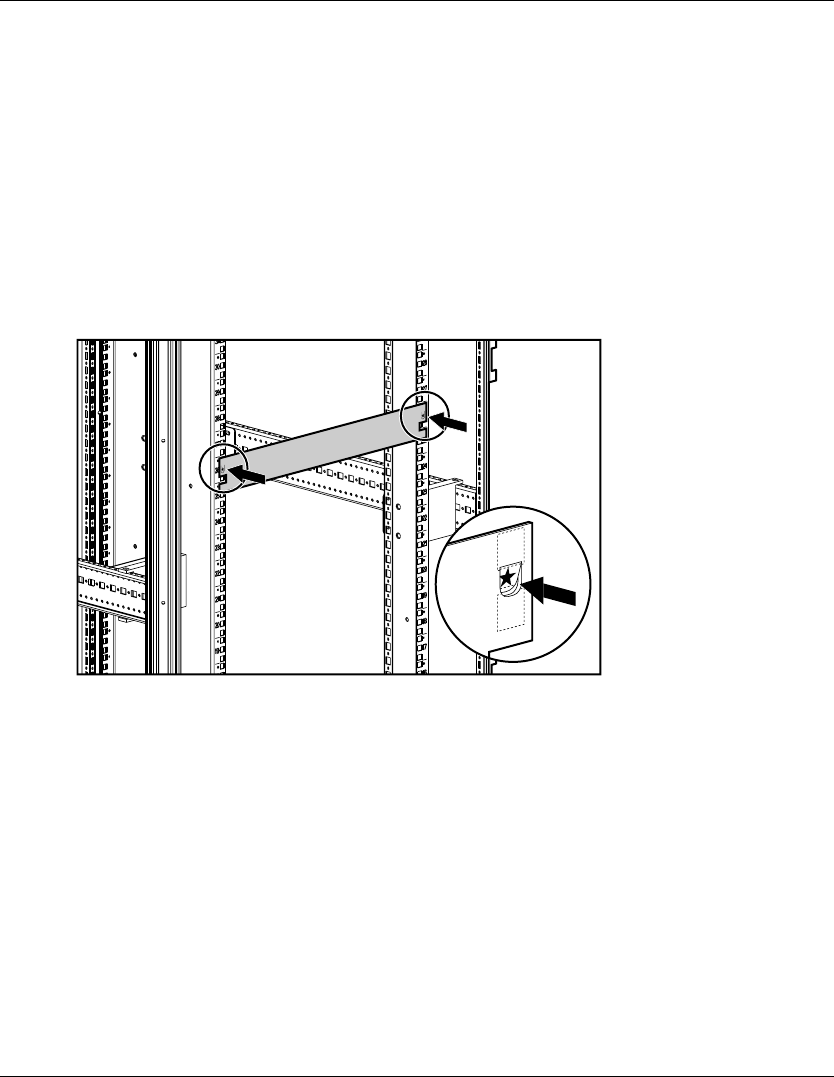
2. Use the template that was shipped with the component to mark the location of the
mounting hardware.
a. Push back the tabs (marked Õ) on the top of the template, and place them in
the correct holes in the mounting rails.
Figure 2-9: Measuring with the rack template
b. Match up the hole pattern, indicated on the sides of the template, with the
hole pattern on the mounting rails.
c. Measuring from the top of the component immediately below the new
component, place the template against the front and rear of the rack frame to
mark the attachment points for the mounting rails and rear cage nuts.