
User manual


Description Spare part number
Equipped with an Intel Core i3-7100U 2.40-GHz dual core processor (2133-MHz FSB, 3.0-GB L3 cache,
15-W), an Intel HD Graphics 620 graphics subsystem with UMA video memory, and a non-Windows
operating system
926276-001
Equipped with an Intel Pentium 4415U 2.30-GHz dual core processor (2133-MHz FSB, 2.0-GB L3 cache,
15-W), an Intel HD Graphics 610 graphics subsystem with UMA video memory, and the Windows 10
operating system
926277-601
Equipped with an Intel Pentium 4415U 2.30-GHz dual core processor (2133-MHz FSB, 2.0-GB L3 cache,
15-W), an Intel HD Graphics 610 graphics subsystem with UMA video memory, and a non-Windows
operating system
926277-001
Before removing the system board, follow these steps:
1. Shut down the computer. If you are unsure whether the computer is o or in Hibernation, turn
the computer on, and then shut it down through the operating system.
2. Disconnect all external devices connected to the computer.
3. Disconnect the power from the computer by rst unplugging the power cord from the AC outlet, and
then unplugging the AC adapter from the computer.
4. Remove the optical drive (see Optical drive on page 35), and then remove the following components:
a. Bottom cover (see Bottom cover on page 36)
b. Battery (see Battery on page 38)
c. Hard drive (see Hard drive on page 39)
d. Solid-state drive (see Solid-state drive on page 43)
e. Fan (see Fan on page 49)
When replacing the system board, be sure to remove the following components from the defective system
board and install them on the replacement system board:
●
WLAN module (see WLAN module on page 41)
●
Memory module (see Memory module on page 44)
●
Heat sink (see Heat sink on page 54)
●
USB port board cable (see USB port board cable on page 57)
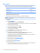
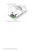
Remove the system board:
1. Disconnect the following cables from the system board:
(1) Power connector cable
(2) WLAN antenna cables
NOTE: The #1/white WLAN antenna cable connects to the WLAN module "#1/Main" terminal. The #2/
black WLAN antenna cable connects to the WLAN module "#2/Aux" terminal.
(3) Display panel ZIF connector cable
(4) Speaker cable
(5) TouchPad ZIF connector cable
Component replacement procedures 51