HP StorageWorks Enterprise Virtual Array 3000/5000 user guide (VCS 3.110) This user guide contains conceptual and procedural information about the HP StorageWorks Enterprise Virtual Array and its online interface.
Legal and notice information © Copyright 2003-2007 Hewlett-Packard Development Company, L.P. Hewlett-Packard Company makes no warranty of any kind with regard to this material, including, but not limited to, the implied warranties of merchantability and fitness for a particular purpose. Hewlett-Packard shall not be liable for errors contained herein or for incidental or consequential damages in connection with the furnishing, performance, or use of this material.
Contents About this guide . . . . . . . . . . . . . . . . . . . . . . . . . . 13 1 System description . . . . . . . . . . . . . . . . . . . . . . . . . 17 2 Startup and operation . . . . . . . . . . . . . . . . . . . . . . . 31 Overview . . . . . . . . Intended audience . . Related documentation Conventions . . . . . . Document conventions Text symbols . . . . Equipment symbols . . Rack stability . . . . . . Getting help . . . . . . HP technical support . HP storage website .
Setting up a controller pair using the OCP Installing Command View EVA . . . . . . . Installing Optional EVA Software Licenses . . System shutdown and power up . . . . . . . . . . . . . . . . . . . . . . . . . . . . . . . . . . . . . . . . . . . . . . . . . . . . . . . . . . . . . . . . . . . . . . . . . . . . . . . . . . . . . . . . . . . . . . . . 3 Enterprise Virtual Array operation . . . . . . . . . . . . . . . . . Best practices . . . . . . . . . . . . . . . .
Navigating the error display . . . . . . . . . Viewing the reporting group feature . . . . . Verifying enclosure operation . . . . . . . . . . Status monitoring and display . . . . . . . . . . Enclosure status icons . . . . . . . . . . . . Fibre Channel loop switches . . . . . . . . . . . . . Power-on self test . . . . . . . . . . . . . . . Reading the switch LEDs . . . . . . . . . . . . Problem isolation . . . . . . . . . . . . . . . HSV controllers . . . . . . . . . . . . . . . . . .
Finnish notice . . . . . . . . . French notice . . . . . . . . . German notice . . . . . . . . Greek notice . . . . . . . . . Hungarian notice . . . . . . . Italian notice . . . . . . . . . Latvian notice . . . . . . . . . Lithuanian notice . . . . . . . Polish notice . . . . . . . . . Portuguese notice . . . . . . . Slovakian notice . . . . . . . . Slovenian notice . . . . . . . . Spanish notice . . . . . . . . Swedish notice . . . . . . . . Germany noise declaration . . . . . Japanese notice . . . . . . .
0.4.en.04 CRITICAL condition—Low temperature . . . . . . . . . . 0.4.en.05 UNRECOVERABLE condition—High temperature . . . . . EMU conditions . . . . . . . . . . . . . . . . . . . . . . . . . . Resetting the EMU . . . . . . . . . . . . . . . . . . . . . . . 07.01.01 CRITICAL condition—EMU internal clock . . . . . . . . . 07.01.02 UNRECOVERABLE condition—EMU interrupted . . . . . . 0.7.01.03 UNRECOVERABLE Condition—Power supply shutdown . . . 0.7.01.04 INFORMATION condition—EMU internal data . . . . . . 0.7.
Replacing a disk drive . . . . . . . . . Inserting disk drives into a running EVA How to install a drive blank . . . . . . . How to remove a drive blank . . . . . . Protecting fiber optic connections . . . . . . . . . . . . . . . . . . . . . . . . . . . . . . . . . . . . . . . . . . . . . . . . . . . . . . . . . . . . . . . . . . . . . . . . . . . . . . . . . . . . . . . . . . . . . . . . . . . . . . . . . . . . . . . . . . . . . . . . . . . . . . . . . . . . . .
Figures 1 ..Enterprise Virtual Array 2C12D configuration . . . . . . . . . . . . . . . . . . . 17 2 ..Enterprise Virtual Array storage solution . . . . . . . . . . . . . . . . . . . . . . 20 3 ..Command View EVA interface window . . . . . . . . . . . . . . . . . . . . . . 4 ..Storage system hardware components . . . . . . . . . . . . . . . . . . . . . . . 21 23 5 ..FC drive enclosure . . . . . . . . . . . . . . . . . . . . . . . . . . . . . . . 6 ..FC loop switch—bezel and front view . . . . . . . .
39 ..Enclosure address bus components with shelf ID expansion cables . . . . . . . . . . . 84 40 ..Typical operational LED status displays—enclosure front . . . . . . . . . . . . . . . 89 41 ..Location of LED status displays—enclosure rear . . . . . . . . . . . . . . . . . . . 90 42 ..FC loop switch 91 43 44 45 46 . . . . . . . . . . . . . . . . . . . . . . . . . . . . . . . . ..Fibre Channel switch LEDs . . . . . . ..HSV110 controller—front and rear views ..Controller OCP . . . . . . . . . . ..
Tables 1 ..Document conventions . . . . . . . . . . . . . . . . . . . . . . . . . . . . . 2 ..Failback Preference Settings . . . . . . . . . . . . . . . . . . . . . . . . . . . 14 46 3 ..Failback Settings by Operating System . . . . . . . . . . . . . . . . . . . . . . 48 4 ..Impact on virtual disk presentation when changing failover/failback setting . . . . . . . 48 5 ..WWN push-button functions . . . . . . . . . . . . . . . . . . . . . . . . . . . 38 6 ..System password push-button functions . .
38 ..Fibre Channel switch specifications . . . . . . . . . . . . . . . . . . . . . . . . 129 39 ..Controller enclosure physical specifications . . . . . . . . . . . . . . . . . . . . 129 40 ..Controller power supply AC power requirements . . . . . . . . . . . . . . . . . . 129 41 ..AC input current and wattage . . . . . . . . . . . . . . . . . . . . . . . . . . 130 42 ..Controller power supply output specifications . . . . . . . . . . . . . . . . . . . . 130 43 ..
About this guide This user guide provides information to help you: • • • • • • • • Learn about the HP StorageWorks Enterprise Virtual Array and its components. Start up your storage system. Operate your storage system. Understand HP Command View EVA and its role in the virtual array. Understand regulations and specifications. Understand EMU-generated error condition reports. Understand HSV fault management concepts. Install customer replaceable units.
Conventions Conventions consist of the following: • Document Conventions • Text Symbols • Equipment Symbols Document conventions The document conventions included in Table 1apply in most cases.
Any enclosed surface or area of the equipment marked with these symbols indicates the presence of electrical shock hazards. Enclosed area contains no operator serviceable parts. WARNING: To reduce the risk of personal injury from electrical shock hazards, do not open this enclosure. Any RJ-45 receptacle marked with these symbols indicates a network interface connection.
NOTE: For continuous quality improvement, calls may be recorded or monitored. Be sure to have the following information available before calling: • • • • • • Technical support registration number (if applicable) Product serial numbers Product model names and numbers Applicable error messages Operating system type and revision level Detailed, specific questions HP storage website The HP website has the latest information on this product, as well as the latest drivers. Access storage at: http://www.hp.
1 System description This chapter provides an overview of the Enterprise Virtual Array and its components. Introduction The HP StorageWorks Enterprise Virtual Array is a high performance, scaled capacity on demand, "virtual" RAID storage solution. A complement of the current modular array family of StorageWorks solutions (ema8000/ema12000/ema16000), it can coexist in the same Fibre Channel SAN while providing 2-Gbps end-to-end Fibre Channel technology readiness.
• Virtualization technology, Vraid, enables data to be distributed from 8 to 240 disks to increase disk spindle count far beyond traditional RAID sets. This virtualization method also optimizes storage for the best performance of a specific configuration and application. The Enterprise Virtual Array eliminates tedious management functions to provide the best performance possible.
virtual disk capacity and redundancy levels. All of this work is done from a central location—Command View EVA. See the Command View EVA online help for more information. Three levels of virtualization are possible within a SAN—server, fabric, and storage system. • Server level—useful for small systems—StorageWorks Virtual Replicator implements small scale virtualization of storage in a Windows NT, Windows 2000, Windows Server 2003 and Novell NetWare environment.
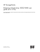
Host Data Command View EVA Control and Monitor Commands Host Data Host Data Fabric Control Input Monitoring Output Browser VCS Administrator Storage System CXO8058A Figure 2 Enterprise Virtual Array storage solution Command View EVA As the only user interface to the Enterprise Virtual Array, Command View EVA resides on the HP OpenView Storage Management Appliance (management appliance) and is opened via a Web browser.
• Content pane—located on the right side of the window, below the Session pane. It is the largest window and is where most administrative tasks are performed. Figure 3 shows the Command View EVA interface main window. Figure 3 Command View EVA interface window For more information, see ???. Command View EVA online help You will find an extensive online help system for Command View EVA. Three levels of help are available: 1. Application—Activated by clicking Help on the Session pane.
VCS benefits VCS provides scalable capacity on-demand, helps improve performance, increases disk utilization efficiency, and allows for easy dynamic storage expansion by providing the following features: • High-density packaging and support of more disks per controller pair. Up to 24TB of disk storage in approximately 5.9 square feet (0.5 square meters) using 168 disks. • Virtually Capacity-Free Snapshot (Vsnap) function that saves significant disk space and improves disk utilization efficiency.
• Fibre Channel drive enclosure—Holds disk drives, power supplies, blowers, Input/Output (I/O) modules, transceivers, and an Environmental Monitoring Unit (EMU). • Fibre Channel loop switch—Provides twelve-port central interconnect for Fibre Channel Arbitrated Loops (FC-AL) following the ANSI FC-AL standard. • HSV Controller—Manages communications between host systems and other devices. A pair of controllers is included in the Enterprise Virtual Array. • Rack—A variety of floor-standing racks are available.
Each hardware component is identified in the following sections and is described in detail in Storage System Hardware Components.
Bezel Front CXO8242A Figure 6 FC loop switch—bezel and front view NOTE: Each bezel covers two FC loop switches in a space capacity of 1U. One "U" is 44.45 mm (1.75 inches) high. EVA5000 HSV110 controllers Two high-performance HSV110 controllers are contained in one EVA5000 rack.
CXO7943A CXO7944B Figure 7 HSV110 controller location—front and rear views EVA3000 HSV100 controllers The HSV100 controllers serve as the interface between the storage system hardware and the SAN. All host I/Os and all Command View EVA management commands are processed by the controllers. Up to four drive enclosures are supported by each HSV100 controller pair. Figure 8 shows the HSV100 controller. Two high-performance HSV100 controllers are included in each EVA3000 storage system.
Front Rear CXO8054B Figure 8 HSV100 controller—front and rear views Rack The rack provides the capability for mounting standard 483mm (19in) wide controller and drive enclosures. Three types of racks are available with your Enterprise Virtual Array 5000: • 9000-Series 42U rack—Available in graphite with a depth of 909mm (35.8in) with industry standard 19in mounting rails. • 9000-Series 41U rack—Available in graphite with a depth of 993mm (39.1in) with industry standard 19in mounting rails.
• Power Distribution Units (PDUs) Figure 9 shows the 42U rack. Front Rear 42U CXO7945B Figure 9 42U rack Hosts and the Enterprise Virtual Array This section describes how the host servers fit in the overall Enterprise Virtual Array.
SAN considerations Ensure that your SAN components are all supported for use with the Enterprise Virtual Array. Design your SAN with an HP standard topology or by following the HP SAN design rules for creating custom topologies. Refer to the HP StorageWorks SAN Design Reference Guide for help with topology rules. The most up-to-date version of this guide can be found on the HP website at http://h18004.www1.hp.com/products/storageworks/san/documentation.html.
System description
2 Startup and operation This chapter provides the procedures necessary to continue installation and startup of your Enterprise Virtual Array. Please contact an authorized HP service representative to assist with installation.
Network Interconnection Browser Browser Non-Host Host X FCA Storage Management Appliance FCA Host Z FCA FCA Command View EVA Fabric 2 Fabric 1 FP1 FP2 FP1 Cache Mirror Port Controller A Loop Loop Pair 1 Pair 2 B FP2 Controller B Loop Loop Pair 2 Pair 1 B Drive Enclosures A A FP = Fibre (Host) Port FCA = Fibre Channel Adapter CXO8099B Figure 10 Block diagram of the storage system’s connections EVA3000 storage system connections Figure 10 shows a typical Enterprise Virtual Array 3000 SA
7. Make virtual disks available to their hosts. Refer to the storage system software documentation for each host’s operating system. Gathering Information Below is important information you need to know prior to operating the Enterprise Virtual Array. Retrieve the items described below to assist you in completing initialization.
Table 2 Failback Preference Settings Setting Point in time Behavior No preference At initial presentation The units are alternately brought online to Controller A or to Controller B. On dual boot or controller resynch If cache data for a LUN exists on a particular controller, the unit will be brought online there. Otherwise, the units are alternately brought online to Controller A or to Controller B. On controller failover All LUNs are brought online to the surviving controller.
Setting Point in time Behavior Path A - Failover/ Failback At initial presentation The units are brought online to Controller A. On dual boot or controller resynch If cache data for a LUN exists on a particular controller, the unit will be brought online there. Otherwise, the units are brought online to Controller A. On controller failover All LUNs are brought online to the surviving controller. On controller failback All LUNs remain on the surviving controller.
Changing virtual disk failover/failback setting Changing the failover/failback setting of a virtual disk may impact which controller presents the disk. Table 4 identifies the presentation behavior that results when the failover/failback setting for a virtual disk is changed. NOTE: If the new setting causes the presentation of the virtual disk to move to a new controller, any snapshots or snapclones associated with the virtual disk will also be moved.
• • • • • • Move the rack. Stabilize the rack. Inspect the storage system. Install the controller cache batteries. Apply power. Attach the controllers to the fabric. Entering data using the OCP Two pieces of data critical to initial setup must be entered into the OCP: • WWN—Mandatory to complete setup. • Storage system password—Optional. A password is a security interlock that allows only specific instances of Command View EVA to access the storage system.
CXO7601C Figure 12 Location of the World Wide Name label Entering the WWN Table 5 defines the push-button functions when entering the WWN or the WWN checksum. NOTE: The following sections describe procedures that require use of the OCP. For more information about the OCP, see Operator Control Panel . Table 5 WWN push-button functions Button Function Selects a WWN or checksum character by scrolling up through the character list one character at a time.
5. Press next. or until the first character is displayed. Press to accept this character and select the 6. Repeat Step 5 to enter the remaining characters. 7. Press to accept the WWN and select the checksum entry mode. NOTE: For the location of the WWN Checksum, see Figure 11. Entering the WWN checksum The second part of the WWN entry procedure is to enter the 2-character checksum, HS, as follows. 1. Verify that the initial WWN checksum displays 0 in both positions. 2.
2. With either of the default menus (Storage System Name or Node World Wide Name) displayed, press any push-button to select the menu tree. 3. Press to cycle through the displays until System Password is active (flashing). 4. Press to select the system password function. 5. When the System Password function is flashing, press 6. To change the password, press or to select the change password function. to show Yes and press .
NOTE: The storage system may take a long time to complete the necessary cache flush during controller shutdown when snapshots are being used. The delay may be particularly long if multiple child snapshots are used, or if there has been a large amount of write activity to the snapshot source Vdisk. To shut the entire system down, perform the following steps: 1. Launch Command View EVA. Click the HSV Storage Network icon to discover the storage systems to ensure they are presented. 2.
Figure 14 Shutdown Options page 4. In the System Shutdown section of the Content pane, click Power Down to achieve the effect described to the right of the button. If a delayed shutdown is desired, enter a value in the Shutdown delay box to set a time delay (in minutes) to preface system shutdown initiation. Wait for the shutdown to complete before proceeding. The HSV controllers will perform an orderly shutdown and then power off. 5. Turn off the power switch on the rear of each HSV controller. 6.
4. Wait three minutes and then verify that all disk drives are ready. The drive ready indicator and the drive online indicator should be on (green). 5. Power on the upper HSV controller. It will assume the roll of master controller. 6. Wait 10 seconds and then power on the lower controller. It will assume the roll of slave controller. 7. Verify that the (Operator Control Panel) OCP display on each controller displays the storage system name and the EVA WWID. 8.
Startup and operation
3 Enterprise Virtual Array operation This chapter presents the tasks that you might need to perform during normal operation of the storage system. Best practices For useful information on managing and configuring your storage system, refer to the HP StorageWorks Enterprise Virtual Array configuration best practices white paper available from http://h71028.www7.hp.com/ERC/downloads/5982-9140EN.pdf.
Table 7 Failback preference settings Setting Point in time Behavior No preference At initial presentation The units are alternately brought online to Controller A or to Controller B. On dual boot or controller resynch If cache data for a LUN exists on a particular controller, the unit will be brought online there. Otherwise, the units are alternately brought online to Controller A or to Controller B. On controller failover All LUNs are brought online to the surviving controller.
Setting Point in time Behavior Path A - Failover/ Failback At initial presentation The units are brought online to Controller A. On dual boot or controller resynch If cache data for a LUN exists on a particular controller, the unit will be brought online there. Otherwise, the units are brought online to Controller A. On controller failover All LUNs are brought online to the surviving controller. On controller failback All LUNs remain on the surviving controller.
Table 8 Failback Settings by Operating System Operating system Default behavior Settings supported Autoback done by the host No Preference, Path A/B - Failover Only. Tru64 UNIX Host follows the unit All settings allowed. Recommended setting: Path A/B - Failover/Failback. OpenVMS (7.3-1 and greater) Host follows the unit All settings allowed. Recommended setting: Path A/B - Failover/Failback. Windows® Auto failback done by the host No Preference, Path A/B - Failover Only.
Storage system shutdown and powerup The storage system is shut down using HP Command View EVA. The shutdown process performs the following functions in the indicated order: 1. 2. 3. 4. 5. Flushes cache Removes power from the controllers Disables cache battery power Removes power from the drive enclosures Disconnects the system from HP Command View EVA NOTE: The storage system may take a long time to complete the necessary cache flush during controller shutdown when snapshots are being used.
NOTE: Before applying power to the rack, ensure that the power switch on each HSV controller is off. 3. Power on the circuit breakers on both EVA rack PDUs. Verify that all drive enclosures are operating properly. The status indicator and the power indicator should be on (green). 4. Wait three minutes and then verify that all disk drives are ready. The drive ready indicator and the drive online indicator should be on (green). 5. Power on the upper controller. It takes the roll of master controller. 6.
5. Enter CAPTURE CONFIGURATION, specifying the full path and filename of the output files for the configuration data. The configuration data is stored in a series of from one to five files, which are SSSU scripts. The file names begin with the name you choose, with the restore step appended. For example, if you specify a file name of LargeEVA.txt, the resultant configuration files would be LargeEVA_Step1A.txt, LargeEVA_Step1B, etc. The contents of the configuration files can be viewed with a text editor.
Adding disk drives to the storage system As your storage requirements grow, you may be adding disk drives to your storage system. Adding new disk drives is the easiest way to increase the storage capacity of the storage system. Disk drives can be added online without impacting storage system operation. CAUTION: When adding disks to an expansion cabinet on an EVA5000, do not install a disk in bays 12, 13, or 14 in enclosures 17, 20, or 24.
Figure 15 Disk drive activity indicator Creating disk groups The new disks you add will typically be used to create new disk groups. Although you cannot select which disks will be part of a disk group, you can control this by building the disk groups sequentially. Add the disk drives required for the first disk group, and then create a disk group using these disk drives. Now add the disk drives for the second disk group, and then create that disk group.
1 2 CX8167-ST Figure 16 Sequential building of vertical disk groups 1. Disks installed in first group 2. Disks installed in second group Adding a disk drive This section describes the procedure for adding a Fibre Channel disk drive. Removing the drive blank 1. Grasp the drive blank by the two mounting tabs (see Figure 17). 2. Lift up on the lower mounting tab and pull the blank out of the enclosure. 2 1 CXO7359B ˚ Figure 17 Removing the drive blank 1.
Changing the Device Addition Policy To prevent the storage system from automatically grouping a new disk drive that may have the incorrect firmware on it, the Device Addition Policy must be checked and set to manual if necessary: 1. Open Command View VA and in the Navigation pane select the storage system. The Initialized Storage System Properties window opens. 2. 3. 4. 5.
• Check the following using Command View EVA. . • Navigate to the disk drive and check the operational state. It should be • Record the Model number and the Firmware version. Check the firmware version against the supported disk firmware in the HP StorageWorks Enterprise Virtual Array release notes. The most current edition of the release notes can be downloaded from the following website: http://www.hp.com/go/eva5000 Click Technical documentation.
covers or dust caps provided by the manufacturer. These covers are removed during installation, and are installed whenever the transceivers or cables are disconnected. Cleaning the connectors should remove contamination. The transceiver dust caps protect the transceivers from contamination. Do not discard the dust covers. CAUTION: To avoid damage to the connectors, always install the dust covers or dust caps whenever a transceiver or a fiber cable is disconnected.
Enterprise Virtual Array operation
4 Storage system hardware components This chapter describes the Enterprise hardware components. Fibre Channel drive enclosures The drive enclosure contains the disk drives used for data storage. A storage system includes multiple drive enclosures. The major components of the enclosure are: • 2.125-Gb, dual loop, 14-drive enclosure. • Dual-loop, FC-AL I/O modules and cable components that are the interface between the drives and the host controllers. • Fiber optic cables. • Copper Fibre Channel cables.
1 2 Front Rear 3 4 6 5 8 7 9 CXO7882A Figure 20 FC drive enclosure—front and rear views 1. 2. 3. 4. 5. 6. 7. 8. 9. Drive bay 1 Drive bay 14 EMU I/O module B Blower 1 Power supply 1 Blower 2 Power supply 2 I/O module A FC-AL I/O modules Two I/O modules (see Figure 23 and Figure 24) provide the interfaces between the drive enclosure and the controllers. They route data to and from the drives using Loop A and Loop B, the dual-loop configuration.
CXO7421A Figure 21 I/O module B CXO7420A Figure 22 I/O module A Enterprise supports only dual-controller, dual-loop operation. Each controller is connected to both the I/O module A and I/O module B in each drive enclosure. The A and B I/O modules are functionally identical, but they are not interchangeable (see Figure 23 for I/O module locations). The physical differences between the modules ensure that you can install: • The A module (1) only at the right end of the enclosure, behind drive bay 1.
2 1 CXO7951A Figure 23 I/O module locations 1. I/O module A 2. I/O module B The I/O modules are major components in the Fibre Channel loop. Each module has two ports that can both transmit and receive data for bidirectional operation. Activating a port requires connecting a transceiver to the port via fibre optic cables. The port function depends upon the loop (see Figure 24). 4 2 3 1 CXO7954A Figure 24 Input and output ports 1. 2. 3. 4.
Table 10 Operational I/O module status indicators Top Power Bottom Descriptions Off On Off • I/O Module is operational On Flashing, then On On • Top port—Fibre Channel drive enclosure signal detected. • Power—Flashes for about 90 seconds after initial power application, then remains constant. • Bottom port—Fibre Channel drive enclosure signal detected. On On On • Top port—Fibre Channel drive enclosure signal detected. • Power—Present.
• The I/O module is replaced, if defective. • The overcurrent condition no longer exists. NOTE: A disabled I/O module cannot transfer data and disconnects all the drives in the enclosure from the loop. Fiber optic cables The Enterprise Virtual Array Fibre Channel 9000-Series implementation uses orange, 50-µm, multi-mode, fibre optic cables. Figure 25 shows the fibre optic cable assembly, which consists of two, 2-m fibre optic strands and small form-factor connectors on each end.
CXO8164A Figure 26 Copper Fibre Channel cable Fibre Channel disk drives The Fibre Channel drives are hot-pluggable and include the following features: • Dual-ported 2 Gbps FC-AL interface that allows up to 120 drives to be supported per FC-AL pair. • 36 GB, 72 GB, 146 GB, and 300GB10K and 15K rpm, and additional drives as certified. • Compact, direct-connect design for maximum storage density and increased reliability and signal integrity.
Drive status reporting Three status indicators (see Figure 28) display the drive operational status. Figure 28 Disk drive status indicators 1. Activity indicator 2. Online indicator 3. Fault indicator Table 12 describes the status indicators. Table 12 Disk drive status indicator descriptions Description Status indicator Activity Online This green status indicator is a “drive ready” indicator and is on when the drive is idle. The green status indicator for this icon is controlled by the disk drive.
Table 13 Operational drive status displays Activity On-line Description Fault Flashing (medium speed) On Off Initial startup. On On Off The operational drive is not being accessed. Flashing (high speed) Flashing (medium speed) On The drive is being located. Flashing On Off The drive is operational and active. NOTE: The drive is configured as part of an array. DO NOT replace an active drive.
CXO6824B Figure 29 Drive blank Replacing a disk or drive blank To replace a disk, complete the procedures outlined in Appendix D: Customer Replaceable Units. The disk replacement kit contains detailed replacement instructions. CAUTION: Removing more than one drive at a time can cause the enclosure to overheat. To prevent overheating and ensure proper operation, install a drive of equal or greater capacity, or a drive blank, as soon as possible.
3. 4. 5. 6. AC Input connector with bail Module latch (port-wine colored) Blower tabs (port-wine colored) Blower element Enclosure power The two power supplies mount in the rear of the enclosure. The supplies are autoranging and operate on a country-specific AC input voltage of 202 to 240 VAC ±10%, 50 to 60 Hz, ±5%, (188 to 264 VAC, 47 to 63 Hz). The DC outputs of this power supply are: • +5.1 VDC for the EMU, I/O module, backplane, and drives • +12.1 VDC for the drives • +12.
NOTE: The blower units are field-replaceable units. The units can be replaced, individually, while the system is running. The units are also interchangeable. The failure of a power supply +12.5 VDC circuit disables the associated blower. Power supply and blower status reporting The green status LED on the blower displays the status of both the power supply and the blower. See Table 15 for definitions of the LED displays.
1 CXO7971A Figure 32 EMU location 1. EMU Controls and displays Figure 33 identifies the location and function of the EMU displays, controls, and connectors. 1 2 3 4 5 6 7 CXO6709A Figure 33 EMU controls and displays 1. Status LEDs These 3 LEDs display the EMU and enclosure status. 2. Alphanumeric display A 2–character, 7–segment alphanumeric display of the enclosure functions and status. 3.
WARNING! To reduce the risk of electrical shock, fire, or damage to the equipment, do not plug telephone or telecommunications connectors into the “RS232 ONLY” receptacle. EMU functions The primary functions of the EMU include: • Using the Enclosure Services Processor (ESP) to control the Enclosure Services Interface (ESI) and communicate with the controllers. • Assigning the Enclosure Number (En), based upon the cabinet address bus feature. • Displaying the bay 1 loop ID. • Monitoring enclosure operation.
Table 16 EMU monitoring functions Element Monitored Functions Blowers • Installation • Removal • Type • Speed (rpm) Disk drives • Installation • Removal • Bypass status • Loop ID • Temperature • Drive fault EMU • Temperature • Operation • Type • Revision level Enclosure • Enclosure power • Enclosure fault • Backplane type • Backplane revision level I/O module • Installation • Removal • Status • Type • Revision level Power supplies • • • • • • • • • Transceiver • Type Installation Remov
1 2 3 CXO6819A Figure 34 EMU status LEDs 1. EMU Status LED This flashing green LED is the heartbeat for an operational EMU. 2. Enclosure Power Status LED This green LED is on when both the +5 V DC and +12 V DC are correct. 3. Enclosure Fault LED This amber LED is normally Off. The LED is ON when an enclosure error condition exists. You can determine the EMU and enclosure status by analyzing the EMU LED displays in Table 18.
Table 18 EMU LED displays EMU LED green Power LED green Fault LED amber Status and recommended actions Flashing Flashing Flashing The EMU locate function is active. This display has precedence over all others. Fault conditions cannot be displayed when the locate function is active. Flashing On Off The EMU is operational. The enclosure power (both +5 V DC and +12 V DC) is present and correct. There are NO enclosure faults. Flashing On On The EMU is operational. There is an enclosure fault.
2. Function select (top push-button) 3. Display Group select (bottom push-button) NOTE: 7-segment display limitations preclude displaying uppercase characters B, K, M, N, Q, R, S, T, V, W, X, Y, or Z, or the lowercase characters a, e, f, g, j, k, l, m, p, q, s, t, v, w, x, y, or z. The lowercase characters b, c, d, h, i, o, r, and u displays are similar to the actual characters. Alphanumeric display description The top-level, two-character alphanumeric display (En, Li, rG, Au, and Er), is the display group.
NOTE: Any time you press and release the bottom push-button (see 3, Figure 35), the display will change to En, Li, rG, Au, or Er. A flashing alphanumeric display indicates that you can edit an address, state, or view a condition report. EMU push-button LEDs The push-button LEDs display error conditions and the state of the audible alarm. • When an error condition exists, the top push-button LED is On. • For a single error condition, the LED is On until the error condition is viewed.
• Correct all errors, thereby silencing the alarm until a new error occurs. • “Mute,” or temporarily disable, the alarm by pressing and holding the bottom push-button. The alarm remains Off until another error occurs, or until you enable (“unmute”) the alarm. When a new error occurs, the alarm sounds and the push-button LED is Off. Using the mute feature ensures that you are aware of the more severe errors and provides you with the capability of correcting them promptly.
Disabling the audible alarm CAUTION: Disabling the audible alarm increases the potential of damage to equipment from a reported but unobserved fault. HP does not recommend disabling the audible alarm. Disabling the audible alarm affects only one enclosure. This action does not affect condition report displays on the EMU alphanumeric display or the Command View EVA GUI. To disable the alarm: 1. Press and release the bottom push-button until the alphanumeric display is Au. 2.
A display of 00 indicates that the enclosure is not connected to the enclosure address bus. When this condition exists, there is no EMU-to-EMU communication over the enclosure address bus. This configuration is known as “just-a-bunch-of-disks,” or a JBOD configuration. A display of 01 through 14 indicates that the enclosure is physically connected to the enclosure address bus and can exchange information with other enclosures on the enclosure address bus.
14 13 12 11 10 9 8 7 6 5 4 3 2 1 CXO7956A Figure 36 Enclosure numbering with JBs Enterprise Virtual Array 3000/5000 user guide (VCS 3.
13 13 12 11 10 9 8 13 7 6 5 4 3 2 1 0046a-2 Figure 37 Enclosure numbering with shelf ID expansion cables NOTE: If an expansion rack is used with your Enterprise configuration, the enclosure numbering shown above may change or contain additional numbering. Refer to the HP StorageWorks Enterprise Virtual Array Hardware Configuration Guide for more information. For more information about the reporting group number, see Viewing the Reporting Group Feature.
11 7 6 5 10 4 9 3 2 1 8 CXO7957B Figure 38 Enclosure address bus components with JBs Callouts: Junction Boxes (JB) 1. 2. 3. 4. 5. 6. 7. JB JB JB JB JB JB JB 1–Enclosures 1 and 2 2–Enclosures 3 and 4 3–Enclosures 5 and 6 4–Enclosure 7 5–Enclosures 9 and 10 6–Enclosures 11 and 12 7–Enclosures 13 and 14 Components 8. 9. 10. 11. Bottom terminator JB-to-Enclosure cable JB-to-JB cable Top terminator Enterprise Virtual Array 3000/5000 user guide (VCS 3.
Figure 39 Enclosure address bus components with shelf ID expansion cables Callouts: 1. 2. 3. 4. 5. 6. 7. 8. 9. 10. 11. 12. 13. 14.
• Information condition See Appendix B: EMU Generated Condition Reports for definitions of individual condition reports. When the audible alarm is not muted or disabled, each condition generates a unique audible alarm as described in Audible Alarm Patterns. Using the condition reporting feature The EMU reports errors to you by changing the alphanumeric display to Er and sounding the audible alarm. A condition report has precedence over all other displays. NOTE: An error always generates a condition report.
A CRITICAL condition has precedence over NONCRITICAL and INFORMATION conditions, but does not have precedence over UNRECOVERABLE conditions. When this codition is the most severe active condition, the audible alarm sounds three times per alarm cycle, as shown in Table 20. NONCRITICAL condition A NONCRITICAL condition is less severe than an UNRECOVERABLE condition or a CRITICAL condition.
Condition report format Each condition report identifies the element affected (type and number), and the primary problem (the error code). Appendix B: EMU Generated Condition Reports provides detailed information about each condition report, and includes recommended corrective actions. • Element Type This two-digit hexadecimal display defines the element type reporting the problem. The format for this display is e.t. with a period after each character. Codes 0.1. through F.F. are valid element types.
Condition report analysis As described in Appendix B: EMU Generated Condition Reports, condition report analysis involves: 1. Identifying the element. 2. Determining the major problem. 3. Defining additional problem information. Viewing the reporting group feature Another function of the enclosure address bus is to provide communications within a reporting group. A Reporting Group (rG) is an HSV110 controller pair and the associated drive enclosures.
Verifying enclosure operation Check the enclosure status LEDs in the front, lower right corner (see Figure 40). If the display is not exactly as shown, an error condition exists. To determine the defective element, check the drive status LEDs on the front, the EMU, the power supplies, and the blowers, as well as checking the I/O module status LEDs on the rear (see Table 21). Either of the drive displays in Figure 40 indicates a properly functioning disk.
CXO7959A Figure 41 Location of LED status displays—enclosure rear Table 21 LED status displays EMU LEDs and icons The enclosure power (both the +5 VDC and +12 VDC) is present and correct. There are NO enclosure faults I/O module A and I/O module B LEDsFor information about I/O Module LED status displays, see I/O Module Status Displays. Power supply and blower LEDs Both the power supply and the blower are operational.
Table 22 Enclosure status icon displays Icon On Off Flashing EMU “Heartbeat” Icon (green LED) Power Icon (green LED) Enclosure Status Icon (orange LED) Fibre Channel loop switches The EVA 5000 uses four FC loop switches (Figure 42) to connect all of the drive enclosures to the controller pair using FC cables. Each switch acts as a central point of interconnection and establishes a fault-tolerant physical loop topology. Bezel Front Rear 1 2 3 4 6 5 CXO7884A Figure 42 FC loop switch 1. 2. 3. 4.
If the Port Bypass LEDs are blinking at a constant rate and the POST Fault LED is On, the switch detected a fault during the POST. When a POST detects a fault, contact your authorized service representative. Reading the switch LEDs The Fibre Channel switch contains both system LEDs and port LEDs. The system LEDs indicate the status of the switch, and the port LEDs provide status of a specific port. Figure 43 shows the Fibre Channel switch with the system and port LEDs.
Table 24 Fibre Channel switch port LEDs SFP status LED Green Description Port bypassed LED amber Off Off Indicates that the port does not have an SFP installed and is bypassed by the loop. On Off Indicates that the port is operating normally. The port and device are fully operational. On On Indicates the that port is in a bypassed state. The port is non-operational due to loss of signal, poor signal integrity, or the Loop Initialization Procedure (LIP).
2 Front 1 Rear 10 3 4 5 6 7 8 9 CXO8040A Figure 44 HSV110 controller—front and rear views 1. 2. 3. 4. 5. 6. 7. 8. 9. 10. Bezel OCP HF1 port HF2 port Mirror port 1B port 2B port 1A port 2A port Power input High availability features Two interconnected controllers ensures that the failure of a controller element (such as a power supply, transceiver, fiber optic or copper Fibre Channel cable, Fibre Channel port, and so forth) does not disable the system.
1 2 3 CXO7638A Figure 45 Controller OCP 1. Status LEDs (see LEDs) 2. 40–character alphanumeric display (see LEDs) 3. Push-buttons (see Displaying the Storage System Menu Tree) LEDs The status LEDs indicate the internal status of the controller, as described in Table 22. During initial setup, the status LEDs might not be fully operational.
NOTE: An active (flashing) display, an error condition message, or a user entry (pressing a push-button) overrides the default display. When none of these conditions exist, the default display is active after approximately 15 seconds. Figure 47 Default LCD display Displaying the storage system menu tree The Storage System Menu Tree lets you select information to be displayed (for example, System Information, Fault Management) or select procedures to implement (Shutdown System, System Password).
Table 27 Menu options within the OCP display Menu Options Information Fault Management Shutdown Options System Password Port Config Last Fault Restart Change Password UUID Unique Half Detail View Power Off Clear Password System Uninitialize Current Password Controller Versions Debug Flags Unbypass Loops Print Flags NOTE: To escape any menu, press or wait 5 seconds for the OCP display to revert back to the root display of the Storage System Name and Node Worldwide Name.
Displaying Versions system information When you press , the active display is Versions. From the Versions display you can determine the: • VCS revision level • OCP firmware revision level • PIC (Programmable Integrated Circuit) firmware revision level for: • Address Bus PIC • Battery PIC • Power PC Processor • Quasar NOTE: The terms PIC, PowerPC Processor, Quasar, glue FPGA, and Surge are for development purposes and have no significance for normal operation.
17. Press to display the Battery PIC. 18. Press to display the Versions Menu tree. 19. Press to scroll to the PowerPC Processor. 20. Press to display the PowerPC Processor. 21. Press to display the Versions Menu tree. 22. Press to scroll to the Quasar version. 23. Press to display the Quasar version. 24. Press to display the Versions Menu tree. Shutting down the system CAUTION: To power off the system for more than 96 hours, use Command View EVA.
CAUTION: If you decide NOT to Power Off while working in the Power Off menu, the Power Off System NO option must be displayed before you press the ESC ( ) push-button to avoid power-down. 1. Press to scroll to the Shutdown Options menu. 2. Press to select the Shutdown Options menu. 3. Press to scroll to Power Off. 4. Press to select Power Off. 5. Power Off System NO is displayed. Press YES. 6. Press to accept YES. 7. Press to go to POWER OFF SYSTEM. to accept NO.
5. Press to select POWER OFF SYSTEM. 6. Press to accept NO. Press 7. Press Press to scroll to POWER OFF SYSTEM YES. to accept YES. to select NO. Uninitializing the system Uninitializing the system is another way to shut down the system. This action causes the loss of all storage system data. Since Command View EVA cannot communicate with the disk drive enclosures, the stored data cannot be accessed. This destroys the storage system and all the data.
Password options The password entry options are: • Entering a password during storage system initialization (see Setting Up an HSV110-Series Controller Pair Using the OCP). • Showing the current password. The actual password is not displayed, instead an indicator informs you of whether a password has been set. • Changing a password (see Changing a Password). • Removing password protection (see Clearing a Password). Changing a password For security reasons, you may need to change a storage system password.
Clearing a password Use the following procedure to remove storage system password protection. NOTE: Changing a system password on the controller requires changing the password on any element manager with access to this system. 1. Press to scroll tot he System Password menu. 2. Press to select the System Password menu. 3. Press to scroll to Clear Password. 4. Press to select Clear Password OR press 5. Press to go to Shutdown Options. to keep the password OR press 6.
NOTE: In Figure 48, the connectors are identified by the label printed on the controller. The numbered item captions define the connector function. 2 Front 1 Rear 10 3 4 5 6 7 8 9 CXO8040A Figure 48 HSV110-series controller—front and rear views 1. 2. 3. 4. 5. 6. 7. 8. 9. 10.
For more information about racks and configurations, including expansion and interconnection, refer to the HP StorageWorks Enterprise Virtual Array Hardware Configuration Guide. Power distribution AC power is distributed to the rack through a dual Power Distribution Unit (PDU) assembly mounted at the bottom rear of the rack.
• The standard 50-Hz PDU cable has an IEC 309, 3-wire, 30-A, 50-Hz connector. • The standard 60-Hz PDU cable has a NEMA L6-30P, 3-wire, 30-A, 60-Hz connector. If these connectors are not compatible with the site power distribution, you must replace the PDU power cord cable connector. Each of the two PDU power cables has an AC power source specific connector. The circuit-breaker-controlled PDU outputs are routed to a group of four AC receptacles (see Figure 50).
1 2 3 7 4 5 6 12 8 9 10 11 CXO7571A Figure 51 Dual PDU assembly major components 1. 2. 3. 4. 5. 6. 7. 8. 9. 10. 11. 12. PDU PDU PDU PDU PDU PDU PDU PDU PDU PDU PDU PDU 1 1 1 1 1 1 2 2 2 2 2 2 receptacle A receptacle B receptacle C receptacle D circuit breaker receptacle A receptacle B receptacle C receptacle D circuit breaker During normal operation, the hinged PDU assembly is in the upright position and the rear door is closed.
1 1 3 2 0040a Figure 52 228481–002/22481–003 PDU assembly 1. mounting brackets 2. cord retention brackets 3. grounding cables PDMs There are eight PDMs mounted in the rear of each rack: • Four mounted on the left vertical rail connect to PDU 1. • Four mounted on the right vertical rail connected to PDU 2. Each PDM has six AC receptacles and two thermal circuit breakers. The PDMs distribute the AC power from the PDUs to the enclosures.
1 2 3 CXO7568B Figure 53 Rack PDM 1. Power receptacles 2. Thermal circuit breakers 3. IEC309 AC power connector 252638–001 PDM model The 339388–001 PDM mounting brackets are assembled at the top and bottom of each 252638-001 PDM and attach to the rack with either a right- or left-side orientation. See Rack-mounted 252638-001 PDM for this PDM assembly. Enterprise Virtual Array 3000/5000 user guide (VCS 3.
1 1 0038a Figure 54 Rack-mounted 252638–001 PDM 1. PDM mounting brackets, right-side orientation. Rack AC power distribution The power distribution in an Enterprise Virtual Array rack is the same for all variants. The site AC input voltage is routed to the dual PDU assembly mounted in the rack lower rear. Each PDU distributes AC to a maximum of four PDMs mounted on the left and right vertical rails (see Figure 55). • PDMs 1 through 4 connect to receptacles A through D on PDU 1.
1 6 2 7 3 8 4 9 5 10 CXO8237A Figure 55 Rack AC power distribution 1. 2. 3. 4. 5. 6. 7. 8. 9. 10. PDM 4 PDM 3 PDM 2 PDM 1 PDU 1 PDU 8 PDM 7 PDM 6 PDM 5 PDU 2 Rack System/E power distribution components AC power is distributed to the Rack System/E rack through Power Distribution Units (PDU) mounted on the two vertical rails in the rear of the rack. Up to four PDUs can be mounted in the rack—two mounted on the right side of the cabinet and two mounted on the left side.
The site AC input voltage is routed to each PDU mounted in the rack. Each PDU distributes AC through ten receptacles directly to the storage system components. • PDUs 1 and 3 (optional) are mounted on the left side of the cabinet. Grey power cords connect these PDUs to the number 1 drive enclosure power supplies and to the controller enclosures. • PDUs 2 and 4 (optional) are mounted on the right side of the cabinet.
4 3 2 2 5 6 8 1 7 CXO8238A Figure 56 10000-Series single rack configuration floor space requirements 1. 2. 3. 4. 5. 6. 7. 8. Front door Rear door Rack width 600 mm Service area width 813 mm Rear service area depth 300 mm Rack depth 1000 mm Front service area depth 406 mm Total rack depth 1706 mm If the feet are not fully raised, complete the following procedure: 1.
1 2 CXO7589A Figure 57 Raising a leveler foot 1. Hex nut 2. Leveler foot 3. Carefully move the rack to the installation area and position it to provide the necessary service areas (see Figure 56). To stabilize the rack when it is in the final installation location: 1. Use a wrench to lower the foot by turning the leveler foot hex nut clockwise until the caster does not touch the floor 2. Repeat step 1 for the other feet. 3. After lowering the feet, check the rack to ensure it is stable and level. 4.
A Regulatory notices and specifications This section provides regulatory notices and specifications for the various components of the Enterprise Virtual Array storage system. Regulatory notices Federal Communications Commission (FCC) notice Part 15 of the Federal Communications Commission (FCC) Rules and Regulations has established Radio Frequency (RF) emission limits to provide an interference-free radio frequency spectrum.
Class B equipment This equipment has been tested and found to comply with the limits for a Class B digital device, pursuant to Part 15 of the FCC Rules. These limits are designed to provide reasonable protection against harmful interference in a residential installation. This equipment generates, uses, and can radiate radio frequency energy and, if not installed and used in accordance with the instructions, may cause harmful interference to radio communications.
WARNING! WARNING: To reduce the risk of exposure to hazardous radiation: • Do not try to open the laser device enclosure. There are no user-serviceable components inside. • Do not operate controls, make adjustments, or perform procedures to the laser device other than those specified herein. • Allow only HP authorized service technicians to repair the laser device. Compliance with CDRH regulations The Center for Devices and Radiological Health (CDRH) of the U.S.
• • • • • EN55022 (CISPR 22) - Electromagnetic Interference EN55024 (IEC61000-4-2, 3, 4, 5, 6, 8, 11) - Electromagnetic Immunity EN61000-3-2 (IEC61000-3-2) - Power Line Harmonics EN61000-3-3 (IEC61000-3-3) - Power Line Flicker EN60950 (IEC950) - Product Safety Notice for France DECLARATION D'INSTALLATION ET DE MISE EN EXPLOITATION d'un matériel de traitement de l'information (ATI), classé A en fonction des niveaux de perturbations radioélectriques émis, définis dans la norme européenne EN 55022 concernant
Estonian notice Seadmete jtmete krvaldamine eramajapidamistes Euroopa Liidus See tootel vi selle pakendil olev smbol nitab, et knealust toodet ei tohi koos teiste majapidamisjtmetega krvaldada. Teie kohus on oma seadmete jtmed krvaldada, viies need elektrija elektroonikaseadmete jtmete ringlussevtmiseks selleks ettenhtud kogumispunkti.
Το σύµβολο αυτό στο προϊόν ή τη συσκευασία του υποδεικνύει ότι το συγκεκριµένο προϊόν δεν πρέπει να διατίθεται µαζί µε τα άλλα οικιακά σας απορρίµµατα. Αντίθετα, είναι δική σας ευθύνη να απορρίψετε τον άχρηστο εξοπλισµό σας παραδίδοντάς τον σε καθορισµένο σηµείο συλλογής για την ανακύκλωση άχρηστου ηλεκτρικού και ηλεκτρονικού εξοπλισµού.
is simbolis ant gaminio arba jo pakuot?s rodo, kad io gaminio alinti kartu su kitomis nam? ?kio atliekomis negalima. alintinas ?rangos atliekas privalote pristatyti ? speciali? surinkimo viet? elektros ir elektronin?s ?rangos atliekoms perdirbti. Atskirai surenkamos ir perdirbamos alintinos ?rangos atliekos pad?s saugoti gamtinius iteklius ir utikrinti, kad jos bus perdirbtos tokiu b?du, kuris nekenkia moni? sveikatai ir aplinkai.
Ta znak na izdelku ali njegovi embalai pomeni, da izdelka ne smete odvre?i med gospodinjske odpadke. Nasprotno, odslueno opremo morate predati na zbirali?e, poobla?eno za recikliranje odsluene elektri?ne in elektronske opreme. Lo?eno zbiranje in recikliranje odsluene opreme prispeva k ohranjanju naravnih virov in zagotavlja recikliranje te opreme na zdravju in okolju nekodljiv na?in.
Japanese notice Harmonics conformance (Japan) Taiwanese notice Japanese power cord notice Country-specific certifications HP tests electronic products for compliance with country-specific regulatory requirements, as an individual item or as part of an assembly. The product label (see Figure 58) specifies the regulations with which the product complies.
Figure 58 Typical enclosure certification label NOTE: The certification symbols on the label depend upon the certification level. For example, the FCC Class A certification symbol is not the same as the FCC Class B certification symbol. About countryspecific regulations HP tests electronic products for compliance with countryspecific regulatory requirements, as an individual item or as part of an assembly. The product label specifies the regulations with which the product complies.
CAUTION: An assembled enclosure (all elements installed) weighs more than 65 lbs (29.5 kg) and requires a minimum of two individuals to move. Table 30 defines the dimensions and weights of the enclosure. Table 30 Drive enclosure physical specifications Empty Installed Shipping Carton Carton & pallet Height 131 mm (5.16 in) 131 mm (5.16 in) 641 mm (25.25 in) 768 mm (30.25 in) Width 505 mm (19.875 in) 505 mm (19.875 in) 318 mm (12.5 in) 610 mm (24 in) Depth 448 mm (17.625 in) 448 mm (17.
Table 31 Drive enclosure elements physical specifications Installed Specification Shipping Carton Environmental Monitoring Unit (EMU) Height 114 mm (4.5 in) 210 mm (8.25 in) Width 241 mm (9.5 in) 330 mm (13.5 in) Depth 35 mm (1.375 in) 108 mm (4.25 in) Weight 0.6 kg (1.3 lb) 0.91 lb (2.0 lb) Height 140 mm (5.5 in) 191 mm (7.5 in) Width 159 mm (6.25 in) 203 mm (8.0 in) Depth 83 mm (3.25 in) 229 mm (9.0 in) Weight 0.45 kg (1.0 lb) 0.91 kg (2.0 lb) Height 114 mm (4.5 in) 210 mm (8.
Table 32 Environmental operating specifications Ambient temperature : +10 °C to +35 °C (+50 °F to +95 °F) with an average rate of change of 1 °C/hour maximum and a step change of 3 °C or less. Maintaining the optimum ambient temperature within the specified range ensures that the internal operating temperatures support the drive manufacturer’s MTBF specifications.
Table 35 AC input current and wattage Maximum Nominal Input Voltage Amps Watts Amps Watts 60–Hz Input 100 VAC–JBOD 4.35 436 6.41 641 208 VAC–North America 2.03 419 2.94 609 50–Hz Input 120 VAC–JBOD 3.59 419 5.27 633 220 VAC–North America 1.92 418 2.78 608 230 VAC–North America 1.92 418 2.78 608 240 VAC–Europe 1.76 416 2.
Fibre Channel switch specifications The Fibre Channel Switch requires a clean, dry environment for normal operation. Table 38 lists the specifications for the Fibre Channel Switch. Table 38 Fibre Channel switch specifications Measurement Category Weight approximately 7.5 lbs. Dimensions 8.50 x 1.57 x 16.00 in (W x H x D) the switch with extender is 21.
Table 41 AC input current and wattage Maximum Nominal Amps Input voltage Watts Amps Watts 60-Hz Input 100 VAC–JBOD 4.35 436 6.41 641 208 VAC–North America 2.03 419 2.94 609 120 VAC–JBOD 3.59 419 5.27 633 220 VAC–North America 1.92 418 2.78 608 230 VAC–North America 1.92 418 2.78 608 240 VAC–Europe 1.76 416 2.55 607 50-Hz Input Table 42 Controller power supply output specifications Minimum Voltage Specification Nominal Maximum +3.
Table 43 9000-Series Enterprise 42U Rack Physical Dimensions Configuration Height in / mm Width in / mm Depth in / mm Max Wt lbs / kg Enterprise 2C6D 78.75 / 2000.0 23.7 / 602 35.8 / 909 918 / 416 Enterprise 2C12D 78.75 / 2000.0 23.7 / 602 35.8 / 909 1350 / 612 Enterprise 0C6D 78.75 / 2000.0 23.7 / 602 35.8 / 909 818 / 371 Enterprise 0C12D 78.75 / 2000.0 23.7 / 602 35.
Table 48 10000-Series Enterprise 42U Rack Shipping Dimensions Configurations Height in / mm Width in / mm Depth in / mm Max Wt (packaging) lbs / kg Enterprise 2C6D 86.22 / 2190 32.0 / 813 48.0 / 1220 1111 / 504 Enterprise 2C12D 86.22 / 2190 32.0 / 813 48.0 / 1220 1543 / 700 Enterprise 0C6D 86.22 / 2190 32.0 / 813 48.0 / 1220 1011 / 459 Enterprise 0C12D 86.22 / 2190 32.0 / 813 48.
Table 51 Enterprise Virtual Array AC power specifications Nominal input voltage Specifications 60-Hz Service 202 VAC Voltage Range Power Receptacle Japan 180-220 VAC, 57-63Hz, 32 A, Single Phase 3-wire, 2-pole, IEC 309 208 VAC Voltage Range Power Receptacle North America 180-220 VAC, 57-63Hz, 32 A, Single Phase 3-wire, 2-pole, NEMA L6-30 240 VAC Voltage Range Power Receptacle Europe 208-254 VAC, 57-63 Hz, 32 A, Single Phase 3-wire, 2-pole, IEC 309 50-Hz Service 202 VAC Voltage Range Power Receptacle
Regulatory notices and specifications
B EMU generated condition reports This section provides a description of the EMU generated condition reports that contain the following information: • Element type (et), a hexadecimal number in the range 01 through FF. • Element number (en), a decimal number in the range 00 through 99 that defines a probable cause of the problem. • Error code (ec), a decimal number in the range 00 through 99. • The recommended corrective action.
Table 52 Assigned element type codes Code Element 0.1. Disk Drives (see Drive Conditions) 0.2. Power Supplies (see Figure 30) 0.3. Blowers (see Figure 30 ) 0.4. Temperature Sensors (see Table 53) 0.6 Audible Alarm 0.7. EMU 0.C. Controller OCP LCD1 0.F. Transceivers (see Figure 63) 1.0. Language1 1.1. Communication Port1 1.2. Voltage Sensors (see Table 54) 1. Current Sensors (see Table 54) 8.0 Drive Enclosure1 8.2. Drive Enclosure Backplane 8.7.
• If the EMU determines the drive cannot operate at the Fibre Channel link rate set by the I/O module, the drive bypass function ends and the drive is placed on the loop. This does not generate a condition report. • The EMU issues the condition report 0.1.en.01 when the drive link rate is incompatible with Fibre Channel link rate. • When the EMU cannot determine the drive link rate during the one-minute drive bypass time, the EMU places the drive on the loop.
This error remains active until the problem is corrected. Complete the following procedure to correct this problem: 1. Record all six characters of the condition report. 2. Remove and replace the drive in the enclosure. 3. Observe the drive status LEDs to ensure the drive is operational. 4. Observe the EMU to ensure the error is corrected. 5. If removing and replacing the drive did not correct the problem, replace the drive. 6. Observe the drive status LEDs to ensure the drive is operational. 7.
1 2 CXO7952A Figure 60 Power supply element numbering The following sections define the power supply condition reports. 0.2.en.01 NONCRITICAL Condition—Power Supply AC Input Missing The loss of the AC input to a power supply makes the remaining power supply a single point of failure. This condition report remains active until AC power is applied to the power supply. Complete the following procedure to correct this problem: 1. Record all six characters of the condition report. 2.
1. Record all six characters of the condition report. 2. Ensure that the blower on the power supply is functioning properly. If not, correct the blower condition and wait one minute. 3. Contact your authorized service representative. Blower conditions The format of a blower condition report is 0.3.en.ec, where: • 0.3. is the blower element type number • en. is the two-character blower element number • ec is the error code As shown in Figure 61, blower 1 is in location 1 and blower 2 is in location 2.
To correct this problem, record all six characters of the condition report, then contact your authorized service representative. 0.3.en.03 UNRECOVERABLE condition—Blower failure A blower has stopped. The operational blower now operates at high speed and is a single point of failure. This condition report remains active until the problem is corrected. To correct this problem, record all six characters of the condition report, then contact your authorized service representative. 0.3.en.
• en. is the two-character temperature sensor element • ec is the error code Refer to Table 53 to determine the location of each temperature sensor. Table 53 Temperature sensor element numbering Sensor Sensor Sensor location Sensor location 01. Power Supply 1 Exhaust 10. Drive Bay 7 02. Power Supply 2 Exhaust 11. Drive Bay 8 03. EMU 12. Drive Bay 9 04. Drive Bay 1 13. Drive Bay 10 05. Drive Bay 2 14. Drive Bay 11 06. Drive Bay 3 15. Drive Bay 12 07. Drive Bay 4 16.
4. Ensure that both blowers are operating properly (the LEDs are on) and neither blower is operating at high speed. 5. Verify that the ambient temperature range is +10 °C to +35 °C (+50 °F to +95 °F). Adjust as necessary. 6. Observe the EMU to ensure the error is corrected. 7. If unable to correct the problem, contact your authorized service representative. 0.4.en.
4. If Steps 1, 2 or 3 did not reveal a problem, use Command View EVA to request the HSV110 controller to shut down the drive enclosure. Completing this action will halt the drive enclosure data transfers. 5. Contact your authorized service representative and request assistance. EMU conditions The format of an EMU condition report is 0.7.01.ec, where: • 0.7. is the EMU element type number • 01.
3. Observe the EMU to ensure the error is corrected. 4. If resetting the EMU did not correct the problem, replace the EMU. 5. If unable to correct the problem, contact your HP authorized service representative. 0.7.01.03 UNRECOVERABLE Condition—Power supply shutdown This message only appears on the Command View EVA GUI to report a power supply has already shut down. This message can be the result of the controller shutdown command or an EMU or power supply initiated power shutdown.
0.7.01.11 NONCRITICAL condition—EMU NVRAM write failure The EMU cannot write data to the NVRAM. This condition report remains active until the problem is corrected. Complete the following procedure to correct this problem: 1. Record all six characters of the condition report. 2. Reset the EMU. 3. Observe the EMU to ensure the error is corrected. 4. If resetting the enclosure did not correct the problem, contact your HP authorized service representative. 0.7.01.
5. Observe the EMU to ensure the error is corrected. 6. Reset the EMU, then observe the EMU to ensure the error is corrected. 7. If resetting the EMU did not correct the problem, contact your HP authorized service representative. 0.7.01.15 UNRECOVERABLE condition—EMU hardware failure The EMU has detected an internal hardware problem. This condition report remains active until the problem is corrected. Complete the following procedure to correct this problem: 1.
1. Record all six characters of the condition report. 2. Reset the EMU. 3. Observe the EMU to ensure the error does not recur within the first minute. 4. If the error does recur, contact your HP authorized service representative. The EMU is inoperative and must be replaced as soon as possible. 0.7.01.19 UNRECOVERABLE condition—EMU ESI driver failure The EMU has detected an internal hardware problem. This condition report remains active until the problem is corrected.
0.F.en.02 CRITICAL Condition—Transceiver Data Signal Lost This symptom can occur when a controller has been powered off or a cable has been removed from the transceiver. The transceiver can no longer detect a data signal. This error prevents the controller from transferring data on a loop and eliminates the enclosure dual-loop capability. This error remains active until the problem is fixed.
Table 54 Voltage and Current Sensor Locations Sensor Sensor Element Location 01. Power Supply 1 +5 VDC 02. Power Supply 1 +12 VDC 03. Power Supply 2 +5 VDC 04. Power Supply 2 +1 VDC Use HP Command View EVA to view the voltage and current error thresholds for both +5 VDC and +12 VDC power supplies. 1.2.en.01 NONCRITICAL Condition—High Voltage This condition report indicates that an element voltage is approaching, but has not reached, the high voltage CRITICAL threshold.
To correct this problem, record all six characters of the condition report, then contact your HP authorized service representative. Backplane conditions IMPORTANT: Backplane NVRAM errors usually occur during manufacture. At this time they are identified and corrected. They rarely occur during normal operation. The format of a backplane condition report is 8.2.01.ec, where: • 8.2. is the backplane element type number • 01.
2 1 CXO7951A Figure 64 I/O module element numbering 1. I/O Module A (01) 2. I/O Module B (02) Correction of an I/O module problem normally requires replacing the module. The following sections define the I/O module problem by I/O module location. 8.7.en.01 CRITICAL condition—I/O module unsupported The I/O module Fibre Channel link speed is not supported by the backplane. This error prevents the controller from establishing a link with enclosure drives and eliminates the enclosure dual-loop capability.
8.7.en.12 NONCRITICAL condition—I/O Module NVRAM read failure The system is unable to read data from the I/O module NVRAM. Complete the following procedure to correct this problem: 1. Record all six characters of the condition report. 2. Contact your HP authorized service representative. 8.7.en.13 NONCRITICAL condition—I/O module removed The system detects that an I/O module has been removed. To correct the problem, install an I/O module.
EMU generated condition reports
C Controller fault management This appendix describes how the controller displays events and termination event information. Termination event information is displayed on the LCD. The HP Command View EVA GUI enables you to view controller events. This appendix also discusses how to identify and correct problems. Once you create a storage system, as described in Chapter 2, “Setting Up a Controller Pair Using the OCP,” an error condition message has priority over other controller displays.
GUI event display A problem that generates the Event display reduces the system capabilities. You can use the information in this display (see Figure 66) to diagnose and correct problems. NOTE: The major differences between the Event Display and the Termination Event display are: • The Event display includes an EIP type field; it does not include a Code Flag field. • The Event display includes a Corrective Action Code (CAC) field.
Displaying Detailed Information The Detail View menu lets you examine detailed fault information stored in the Last Termination Event Array (LTEA). This array stores information for the last 32 termination events. Complete the following procedure to display the LTEA information about any of the last 32 termination events: 1. When the Fault Management display is active (flashing), press to select the Detail View menu. The LTEA selection menu is active (LTEA 0 is displayed). 2. Press or 3.
Table 55 Controller Event Text Description File Information Type Description Event Code This hexadecimal code identifies the reported event type. Termination Code (TC) The hexadecimal code specifies the condition that generated the termination code. It might also define either a system or user initiated corrective action. Coupled Crash Control Codes This single digit, decimal character defines the requirement for the other controller to initiate a coupled crash control.0.
D Customer replaceable units This appendix describes the procedures for replacing CRUs. Information about initial enclosure installation, ESD protection, and common replacement procedures is also presented. ESD protection When you replace a CRU, you must take precautions to prevent the possibility of electrostatic discharge (ESD) damaging sensitive electronic items. 1. Always transport and store CRUs in an ESD protective enclosure. 2.
Determining CRU part numbers All elements have a 6–3 spare part number on the product label (see Figure 67). This nine-character number appears immediately below the “Replace with HP Spare” statement. The first six characters (123479) identify the element. The last three characters (–002) define the revision level. The replacement element revision level must be the same as, or greater than, the number on the element being replaced. The higher the revision level, the later the revision.
1 2 CXO6826A Figure 68 Removing a drive 2. Pull on the drive until it disconnects from the backplane connector. CAUTION: The carrier can be dropped due to the rapidly rotating media. To prevent equipment failure, remove the carrier from the enclosure when the media has stopped rotating. This takes approximately 30 seconds. 3. When you are sure that the media is no longer spinning, completely remove the drive from the enclosure. 4.
NOTE: If one or more of the disk drives inserted does not reach the solid green indication after 70 seconds, remove the drive or drives and check for damaged connectors on the disk drive and drive enclosure. If no damage is found, repeat Steps 1 and 2. After two attempts, replace drives that do not reach the solid green indication. When all of the inserted disk drives successfully reach the solid green indication, then repeat Steps 1 and 2 for the next set of 1 to 4 disk drives to be inserted.
2 1 CXO7359B ˚ Figure 70 Installing and removing a drive blank NOTE: When installing drives, start at slot one, and do not leave blank slots between drives. If mixing online and near-online drives, a minimum of 8 online and 8 near-online drives are required. When loading drives into racks, align drives vertically by capacity. How to remove a drive blank Complete the following procedure to remove a drive blank: 1. Grasp the drive blank by the two tabs (1 and 2, Figure 70). 2.
• When to Clean—If a connector may be contaminated, or if a connector has not been protected by a dust cover for an extended period of time, clean it. • How to Clean: a. Wipe the connector with a lint-free tissue soaked with 100% isopropyl alcohol. b. Wipe the connector with a dry, lint-free tissue. c. Dry the connector with moisture-free compressed air. One of the many sources for cleaning equipment specifically designed for fiber optic connectors is: Alcoa Fujikura Ltd.
Glossary This glossary defines terms used in this guide or related to this product and is not a comprehensive glossary of computer terms. µm A symbol for micrometer; one millionth of a meter. For example, 50 µm is equivalent to 0.000050 m. 3U A unit of measurement representing three “U” spaces. “U” spacing is used to designate panel or enclosure heights. Three “U” spaces is equivalent to 5.25 inches (133 mm). See also rack-mounting unit.
array controller See controller. asynchronous Events scheduled as the result of a signal requesting the event or that which is without any specified time relation. audible alarm The Environmental Monitoring Unit (EMU) alarm that sounds when there is a drive enclosure element condition report. The audible alarm can be muted or disabled. backplane An electronic printed circuit board that distributes data, control, power, and other signals to element connectors.
cache battery indicator 1. carrier A drive-enclosure-compatible assembly containing a disk drive or other storage devices. client A software program that uses the services of another software program. The HP Command View EVA client is a standard internet browser. clone See Virtual Disk Copy. communication logical unit number (LUN) See console LUN. condition report A three-element code generated by the EMU in the form where e.t. is the element type (a hexadecimal number), en.
data entry mode The state in which controller information can be displayed or controller configuration data can be entered. On the Enterprise Storage System, the controller mode is active when the LCD on the HSV Controller OCP is Flashing. default disk group The first disk group created at the time the system in initialized. The default disk group can contain the entire set of physical disks in the array or just a few of the disks. See also disk group.
dual power supply configuration See redundant power configuration. dynamic capacity expansion A storage system feature that provides the ability to increase the size of an existing virtual disk. Before using this feature, you must ensure that your operating system supports capacity expansion of a virtual disk (or LUN). EIA Electronic Industries Alliance. A standards organization specializing in the electrical and functional characteristics of interface equipment. EIP Event Information Packet.
Enclosure Services Interface See ESI. Enclosure Services Processor See ESP. Enterprise Virtual Array The Enterprise Virtual Array is a product that consists of one or more storage systems. Each storage system consists of a pair of HSV controllers and the disk drives they manage. A storage system within the Enterprise Virtual Array can be formally referred to as an Enterprise storage system, or generically referred to as the storage system.
Fault Management Code See FMC. Fibre Channel drive enclosure Fibre Channel Arbitrated Loop. The American National Standards Institute’s (ANSI) document that specifies arbitrated loop topology operation. FC HBA Fibre Channel Host Bus Adapter. An interchangeable term for Fibre Channel adapter. See also FCA. FCA Fibre Channel Adapter. An adapter used to connect the host server to the fabric. Also called a Host Bus Adapter (HBA) or a Fibre Channel Host Bus Adapter (FC HBA). See also FC HBA.
Gb Gigabit. A measurement of the rate at which the transfer of bits of data occurs. Sometimes referred to as Gbps. Nominally, a Gb is a transfer rate of 1,000,000,000 (109) bits per second. For Fibre Channel transceivers or FC loops the Gb transfer rates are: • 1 Gb is a transmission rate of 1,062,500,000 bits per second. • 2 Gb is a transmission rate of 2,125,000,000 bits per second. GB Gigabyte. A unit of measurement defining either: • A data transfer rate.
I/O module Input/Output module. The enclosure element that is the Fibre Channel drive enclosure interface to the host or controller. I/O modules are bus speed specific, either 1 Gb or 2 Gb. IDX A 2-digit decimal number portion of the HSV controller termination code display that defines one of 32 locations in the Termination Code array that contains information about a specific event. See also param and TC.
logon Also called login, it is a procedure whereby a user or network connection is identified as being an authorized network user or participant. loop See arbitrated loop. loop ID Seven-bit values numbered contiguously from 0 to 126 decimal and represent the 127 valid AL_PA values on a loop (not all 256 hexadecimal values are allowed as AL_PA values per Fibre Channel). loop pair A Fibre Channel attachment between a controller and physical disk drives.
multi-mode fiber A fiber optic cable with a diameter large enough (50 microns or more) to allow multiple streams of light to travel different paths from the transmitter to the receiver. This transmission mode enables bidirectional transmissions. Network Storage Controller See NSC. NONCRITICAL Condition A drive enclosure EMU condition report that occurs when one or more elements inside the enclosure have failed or are operating outside of their specifications.
PDU Power Distribution Unit. The rack device that distributes conditioned AC or DC power within a rack. petabyte A unit of storage capacity that is the equivalent of 250, 1,125,899,906,842,624 bytes or 1,024 terabytes. physical disk A disk drive mounted in a drive enclosure that communicates with a controller pair through the device-side Fibre Channel loops. A physical disk is hardware with embedded software, as opposed to a virtual disk, which is constructed by the controllers.
read ahead caching A cache management method used to decrease the subsystem response time to a read request by allowing the controller to satisfy the request from the cache memory rather than from the disk drives. reconstruction The process of regenerating the contents of a failed member data. The reconstruction process writes the data to a spare set disk and incorporates the spare set disk into the mirrorset, striped mirrorset or RAID set from which the failed member came. redundancy 1.
small computer system interface See SCSI. Snapclone A virtual disk that can be manipulated while the data is being copied. Only an Active member of a virtual disk family can be snapcloned. The Snapclone, like a snapshot, reflects the contents of the source virtual disk at a particular point in time. Unlike the snapshot, the Snapclone is an actual clone of the source virtual disk and immediately becomes an independent Active member of its own virtual disk family.
may be incapable of recovering or bypassing the failure and will require repairs to correct the condition. This is the highest level condition and has precedence over all other errors and requires immediate corrective action. unwritten cached data Also called unflushed data. See also dirty data. UPS Uninterruptible Power Supply. A battery-operated power supply guaranteed to provide power to an electrical device in the event of an unexpected interruption to the primary power supply.
write back caching A controller process that notifies the host that the write operation is complete when the data is written to the cache. This occurs before transferring the data to the disk. Write back caching improves response time since the write operation completes as soon as the data reaches the cache. As soon as possible after caching the data, the controller then writes the data to the disk drives.
Index Symbols +5.
CAUTIONs air flow, 65 disk drives, 65, 68 CDRH, compliance regulations, 117 Center for Devices and Radiological Health See CDRH certification product labels, 123 changing passwords, 102 checksum, 39 Class A equipment, Canadian compliance statement, 117 Class B equipment, Canadian compliance statement, 117 cleaning fiber optic connectors, 57, 164 clearing passwords, 103 clustering, 17 code flag, 155 Command View EVA defined, 19, 20 commercial environments, use in, 17 component description, 64 components, sto
disk drives compatibility, 160 adding, 52 CAUTIONs about, 65, 68 connecting to backplane, 162 defined, 65 disconnecting from backplane, 161 displaying status, 90 hot swapping, 22 installing, 160 MTBF specifications, 127, 132 overcurrent sensors, 67 overheating, 65 power usage, 69 removing, 162 replacing, 65, 160, 162 reporting status, 66 spinning down, 162 supported, 65 disk drives affecting air flow, 68 display groups error code, Er, 76 audible alarm, Au, 76 enclosure number, En, 76 loop ID, Li, 76 reporti
environmental specifications air quality, 127, 132 altitude, 127 controllers, 130 Fibre Channel Loop Switches, 129 relative humidity, 127, 132 shipping, 132 short term storage, 132 EP, 72 error code selecting display group, 76 error codes, defined, 157 error condition report format, 87 error display, 87 error messages, 72 error queue, 86 error report storage, 87 errors displaying, 72 correcting automatically, 72 ESD protection, 159 ESI, 65, 72 EVA operations, 45 event code, defined, 158 event GUI display, 1
icons battery status, 95 pushbuttons, 95 IDX code display, 156 INFORMATION conditions, 86 audible alarm, 77 defined, 86 drive missing, 137 EMU, 145, 147 INITIALIZE LCD, 99 initializing the system defined, 99 installation software, 32 interface layout, software, 20 internal clock, 144 M J N Management Appliance, 40 Management Appliance, Command View EVA, 31 missing AC input, 139 power supplies, 139, 139 Modular Array family, 17 monitored functions blowers, 73 I/O module, 73 power supply, 73 MTBF, 127, 13
O OCP fault management displays, 156 firmware version, 98 using, 37 OCP pushbutton icons, 103 online help system, 20, 21 OpenView Storage Management Appliance, 20, 40 operating system kit, 33 overcurrent sensors backplane, 67 disk drives, 67 overheating CAUTIONs, 65 preventing, 65 CAUTIONs, 68 disk drives, 68 drive blank, 68 P page-level help, 20, 21 parameter code, 156 parameter code number, 156 password clearing, 103 entering, 102 changing, 102, 102 clearing, 102 entering, 39 removing, 102 PDUs, 105 pe
regulatory notices, 115 relative humidity drive enclosure, 127 short term storage, 127 drive enclosure, 127 operating, 132 shipping, 127, 132 short term storage, 132 release lever, disk drive, 162 removing disk drives, 162 replacement procedures common, 159 CRUs, 159 replacement time, disk drives , 65 replacing disk drives, 160, 162 resetting EMU, 144 RESTART LCD, 99 restarting the system, 99, 100 restarting the system defined, 99 rH displays, 88 rL displays, 88 room temperature See ambient temperature rpm,
temperature condition reports, 141 effect of air flow, 69 sensing, 69, 90 Termination Code See TC termination event GUI display, 155 thermal protection, power supplies, 69 total power sensing, 90 transceivers CRITICAL conditions, 148, 149, 149 loop switches, 24 monitored functions, 73 turning off power, 99 U Uninitializing, 101 unitializing the system, 101 universal disk drives, 65 UNRECOVERABLE conditions blowers no blowers installed, 141 audible alarm, 77 backplane NVRAM, 145 blowers failure, 141 EMU lo