
Instruction Manual
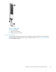

NOTE:
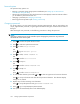
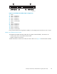
In Figure 48, the connectors are identified by the label printed on the controller. The numbered item
captions defi ne the connector function.
CXO8040
A
Front
Rear
1
2
9
1
0
876 5 43
Figure 48 HSV110-series controller—front and rear views
1. Bezel
2. OCP
3. HF1 port
4. HF2 port
5. Mirror port
6. 1B port
7. 2B port (EVA 5000 only)
8. 1A port
9. 2A port (EVA 5000 only)
10. Power input
HSV100 controllers use copper fiber channel cables, while HSV110 controller use fiber optic fiber
channel cables.
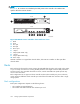
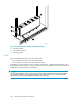
Racks
Each rack has four feet and four casters. Raising the adjustable feet places the rack weight on the casters,
so you can easily move the rack. Lowering the feet places the rack weight on the feet a nd prevents the
rack from moving. The removable front and rear doors, and the removable side panels provide easy
access to the rack interior.
Each configuration has an upper and lower controller enclosure (the controller pair), drive enclosures,
and an expansion bulkhead. Each controller pair and all the associated drive enclosures form a single
storage system.
Rack configurations
Each system configuration depends on the following factors:
• The controller pair (M odel HSV110)
• The number of 3U Fibre Channel drive enclosures per rack
104
Storage system hardware components