
Instruction Manual


• Fibre Channel drive enclosure—Holds disk drives, power supplies, blowers,Input/Output(I/O)
modules, transceivers, and an Environmental Monitoring Unit (EMU).
• Fibre Channel loop switch—Provides twelve-port central interconnect for Fibre Channel Arbitrated
Loops (FC-AL) following the ANSI FC-AL standard.
• HSV Controller—Manages communications between host systems a nd other devices. A pair of
controllers is included in the Enterprise Virtual Array.
• Rack—A variety of floor-standing racks are available.
NOTE:
Your Enterprise Virtual Array may consist of one or more of the above hardware elements, depending
on your configuration.
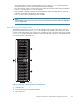
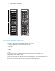
Physical layout of the storage system
The Enterprise Virtual Array consists of a pair of controllers and an array of disk drives. The basic
physical components are shown in Figure 4. The disk dr ives are installed in drive enclosures, which
connect to Fibre Channel (FC) loop switches. The controller p air also connects to the FC loop switches.
A backplane in the drive enclosures distr ibutes commands and data to the drives. The EVA3000 does
not use FC switches on the back end.
1
3
3
2
CXO7941
A
Figure 4 Stora ge system hardware components
1. Controller pa ir
2. FC loop switch (not used in the EVA3000)
3. Drive enclosures
Enterprise Virtual Array 3000/5000 user guide (VCS 3.110)
23