
Manual

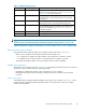
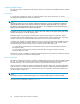


Figure 17 EMU controls and displays
1. Status indicators:
a. EMU—This flashing green is the heartbeat for an operational EMU.
b. Enclosure power—When both the +5 VDC and +12 VD C are correct, this green indicator is on.
c. Enclosure fault—This amber indicator is normally off. The indicator is lit when an enclosure error
condition exists.
2. Alphanumeric disp lay—A two-character, seven–segment alphanumeric display of the enclosure functions
and status.
3. Function select button—The primary function of this button is to select a display group function. The
indicatorisonwhenanerrorconditionexists.
4. Display group select button—This button is used to view display groups and control the audible alarm. The
indicator is on when the audible alarm is muted or disabled.
5. RS23 2 – for use by HP-authorized service representatives
6. LCD ONLY–unused
7. CAB ONLY–enclosure address bus connector
WARNING!
To reduce the risk of electrical shock, fire, or damage to the equipment, do not plug telephone or
telecommunications connectors into the “RS232 ONLY” receptacle.
EMU functions
The primary functions of the EMU include:
• Using the Enclosure Services Processor (ESP) to control the Enclosure Services Inter face (ESI) and
communicate with the contro llers.
• Assigning the Enclosure Number (En), based upon the cabinet address bus feature.
• Displaying the bay 1loopID.
• Monitoring enclosure operation.
• Detecting, reporting, recording, and displaying conditions.
• Displaying EMU, enclosure, and element status.
• Implementing automatic corrective actions for some cond itions.
• Providing enclosure status data to the controllers.
• Reporting the WW N and the logical address of all disk drives.
52
Enterprise Virtual Array hardware components