
Manual

CXO7638
A
1
2 3
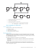
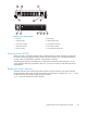
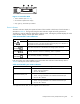
Figure 23 Controller OCP
1. Status indicators (see Table 22)
2. 40–character alphanumeric display
3. Left, righ
t, top, and bottom push buttons
Status indicators
The status indicators display the operational status of the controller. The function of each indicator is
described in Table 22. During initial setup, the status indicators might not be fully operational.
The following sections define the alphanumeric displays modes, including the possible displays, the valid
status indicator displays, and the push button functions.
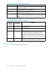
Table 22 Controller status indicato rs
Indicator
Description
Fault
When this i
ndicator is on there is a controller problem. Check either HP
Command Vi
ew EVA or the LCD Fault Management displays for a definition of
the proble
m and recommended corrective action.
Host Link
When this indicator is green, there is a link between the storage system a n d a
host. When red, there is no link between the storage system and a host.
Controller
When this indicator is flashing slowly, a heartb eat, the controller is operating
normally
. When this indicator is not flashing, there is a problem.
Cache Bat
tery
When this i
ndicator is off, the battery assembly is charged. When this indicator
is on, the
battery assembly is discharged.
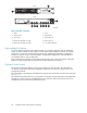
Each port
on the rear of the controller has an associated status indicator loc ated directly above it.
Table 23 lists the port and its status description.
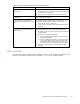
Table 23 Con troll er port status in di cators
Port
Description
Fibre Channel host ports
• Green—N
ormal operation
• Amber—N
osignaldetected
• Off—No
SFP
1
detected
Fibre Channel device ports
• Green—Normal operation
• Amber—No signal detected or the controller has failed the port
• Off—No SFP
1
detected
Fibre Channel cache mirror ports
• Green—Normal operation
• Amber—No signal detected or the controller has failed the port
• Off—No SFP
1
detected
1
On copper Fibre Channel cables, the SFP is integrated into the cable connector.
Enterprise Virtual Array 3000/5000 user guide
69