
- Hewlett-Packard Laptop User Manual
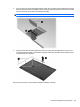
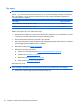
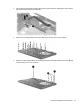
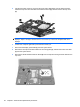
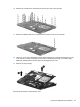
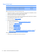
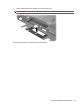
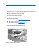
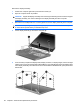
Table Of Contents
- Product description
- External component identification
- Illustrated parts catalog
- Removal and replacement procedures
- Preliminary replacement requirements
- Component replacement procedures
- Service tag
- Computer feet
- Battery
- Switch cover and keyboard
- Memory module
- Optical drive
- Speakers
- WWAN module
- Palm rest
- Hard drive
- WLAN module
- Display assembly on computers with 15-in displays
- Top cover
- Power button board
- RTC battery
- Display assembly on computers with 14-in displays
- Bluetooth module
- Modem module
- USB connector assembly
- Heat sink and fan
- Processor
- System board
- SIM
- Computer Setup
- Specifications
- Computer specifications
- 14.1-in WXGA display specifications
- 15.6-in WXGA display specifications
- Hard drive specifications
- DVD-ROM Drive specifications
- DVD±RW Double-Layer Combo Drive specifications
- Blu-ray Disc ROM Drive with SuperMulti DVD±R/RW Double-Layer specifications
- System DMA specifications, Windows Vista and XP
- System interrupt specifications, Windows Vista
- System interrupt specifications, Windows XP
- System I/O address specifications, Windows Vista
- System I/O address specifications, Windows XP
- System memory map specifications, Windows Vista
- System memory map specifications, Windows XP
- Screw listing
- Torx T8M2.5×6.0 screw
- Torx T8M2.5×4.0 screw
- Phillips PM2.0×2.0 screw
- Phillips PM2.0×3.0 screw
- Phillips PM2.0×3.0 screw
- Phillips PM2.5×6.0 screw
- Phillips PM2.5×11.0 captive screw
- Phillips PM3.0×4.0 screw
- Phillips PM2.0×4.0 screw
- Phillips PM2.5×3.0 screw
- Phillips PM2.5×4.5 screw
- Phillips PM2.5×3.0 broadhead screw
- Phillips PM2.5×7.0 screw
- Phillips PM2.5×9.0 captive screw
- Phillips PM3.0×8.0 screw
- Backup and recovery
- Connector pin assignments
- Power cord set requirements
- Recycling
- Index
RTC battery
Description Spare part number
RTC battery 449137-001
Before removing the RTC battery, follow these steps:
1. Shut down the computer. If you are unsure whether the computer is off or in Hibernation, turn the
computer on, and then shut it down through the operating system.
2. Disconnect all external devices connected to the computer.
3. Disconnect the power from the computer by first unplugging the power cord from the AC outlet and
then unplugging the AC adapter from the computer.
4. Remove the battery (see
Battery on page 63).
5. Remove the following components:
a. Switch cover and keyboard (see
Switch cover and keyboard on page 64)
b. Palm rest (see
Palm rest on page 75)
c. Top cover on 14-in models (see
Top cover on page 90)
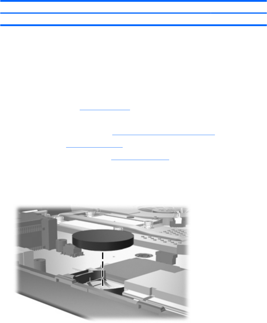
Remove the RTC battery:
1. Position the computer right-side up with the front toward you.
2. Remove the RTC battery from the socket on the system board.
Reverse this procedure to install the RTC battery.
96 Chapter 4 Removal and replacement procedures