
- Hewlett-Packard Laptop User Manual
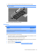

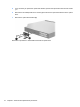
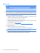
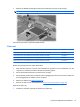
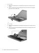
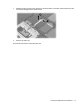
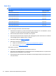
Table Of Contents
- Product description
- External component identification
- Illustrated parts catalog
- Removal and replacement procedures
- Preliminary replacement requirements
- Component replacement procedures
- Service tag
- Computer feet
- Battery
- Switch cover and keyboard
- Memory module
- Optical drive
- Speakers
- WWAN module
- Palm rest
- Hard drive
- WLAN module
- Display assembly on computers with 15-in displays
- Top cover
- Power button board
- RTC battery
- Display assembly on computers with 14-in displays
- Bluetooth module
- Modem module
- USB connector assembly
- Heat sink and fan
- Processor
- System board
- SIM
- Computer Setup
- Specifications
- Computer specifications
- 14.1-in WXGA display specifications
- 15.6-in WXGA display specifications
- Hard drive specifications
- DVD-ROM Drive specifications
- DVD±RW Double-Layer Combo Drive specifications
- Blu-ray Disc ROM Drive with SuperMulti DVD±R/RW Double-Layer specifications
- System DMA specifications, Windows Vista and XP
- System interrupt specifications, Windows Vista
- System interrupt specifications, Windows XP
- System I/O address specifications, Windows Vista
- System I/O address specifications, Windows XP
- System memory map specifications, Windows Vista
- System memory map specifications, Windows XP
- Screw listing
- Torx T8M2.5×6.0 screw
- Torx T8M2.5×4.0 screw
- Phillips PM2.0×2.0 screw
- Phillips PM2.0×3.0 screw
- Phillips PM2.0×3.0 screw
- Phillips PM2.5×6.0 screw
- Phillips PM2.5×11.0 captive screw
- Phillips PM3.0×4.0 screw
- Phillips PM2.0×4.0 screw
- Phillips PM2.5×3.0 screw
- Phillips PM2.5×4.5 screw
- Phillips PM2.5×3.0 broadhead screw
- Phillips PM2.5×7.0 screw
- Phillips PM2.5×9.0 captive screw
- Phillips PM3.0×8.0 screw
- Backup and recovery
- Connector pin assignments
- Power cord set requirements
- Recycling
- Index
2. On 15-in models:
a. Remove the two Phillips PM2.5×3.0 broadhead screws (1) that secure the palm rest to the
computer.
b. Slide the palm rest back toward the display (2), and then lift and rotate the front edge (3) to
gain access to the TouchPad cable.
– or –
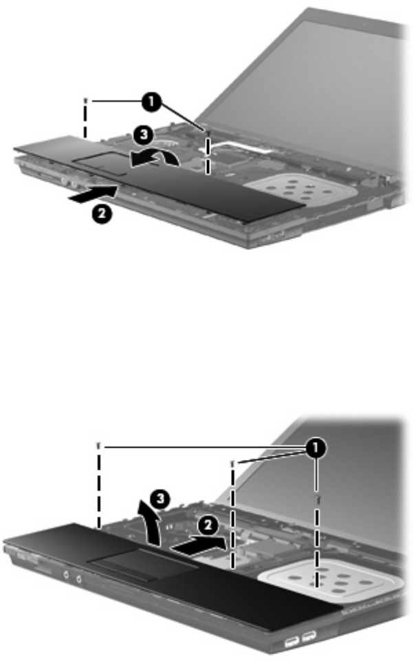
On 14-in models:
a. Remove the three Phillips PM2.5×3.0 broadhead screws (1) that secure the palm rest to the
computer.
b. Slide the palm rest back toward the display (2), and then lift the front edge (3) to gain access
to the TouchPad cable.
76 Chapter 4 Removal and replacement procedures