
- Hewlett-Packard Carrier MultiPath Switch Product Guide
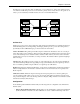

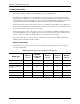

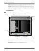

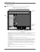
Table Of Contents
- Table of Contents
- About this Guide
- Chapter 1: Overview
- Chapter 2: Hardware Components
- Chapter 3: Installation
- Installation
- Connection
- Connect Power - CMS (14 slot), DC only)
- Connect Power - CMS960 (8 slot) and CMS240 (2 slot), DC only
- Install Power Cord Strain Relief (AC only)
- Power up the System (for AC unit)
- Prevent Electrostatic Discharge Damage
- Assign IP Address
- Install Software Upgrade via CMS Software Update Utility
- Chapter 4: Getting Started with Command Line Interface (CLI)
- Chapter 5: Working with SNMP
- Chapter 6: Call Detail Recording
- Chapter 7: System Alarms
- Chapter 8: Diagnostics/Maintenance
- Appendix A: Getting Acquainted with Tenor CMS in the VoIP Network
- Appendix B: Specifications/Approvals
- GLOSSARY
- INDEX
- WARRANTY

2-6 P/N 480-0005-00-15
Chapter 2: Hardware Components
Rear (with DC power)
NOTE: For pictorial purposes, Figure 2-4 is shown with 1 DS1 card and the CPU card.
Figure 2-4 Tenor CMS Rear View - DC unit
• Card Slots. The rear of the cards requiring a transition module (T1, E1, DS1, CPU) is used for network
connection. The quantity will vary depending upon the number of cards you have inserted.
• Power Plug. Provides wire connections to the -42 to -60 VDC power from the DC feed(s) to the power
receptacles. Both may be used, but only one is required (one must have the power connected to its power
inlet connector).
• Power Receptacle. Power inlet receives DC power from the power plug.
• Circuit Breaker. There is one circuit breaker for each power connection; an arrow from each one indi-
cates which breaker controls which power receptacle connection. The top circuit breaker controls the left
power receptacle; the bottom circuit breaker controls the right power receptacle. When you push the
rocker to ON, the breaker will be closed (a red indicator shows the user that the contacts are closed).
When you push the rocker to OFF, the contacts will open. Both circuit breakers must always be open,
even if only one power source is connected to the chassis, to ensure all power is disconnected from the
power supplies.
• Earth Ground Terminal An earth ground terminal is provided to connect to a supplemental earth
ground.
• ESD Socket. A ground connection is provided for ESD protection.
10
1
2
3
4
DS1
1
2
3
4
10/100
Ethernet
Link TX/RX
Link TX/RX
1
2
3
4
Console
Config
1
2
3
4
10/100
Ethernet
Link TX/RX
1
2
3
4
CPU
Off On
Off On
0 1
Off On
0 1
© Copyright 2001 Quintum Technologies Inc.
-48 |RTN|-48 |RTN|
-48 |RTN|
-48 |RTN|
Air Exhaust
Card
Earth Ground
Terminal
ESD Socket
Power Plug
Power Receptacle
Power Receptacle
Power Plug
Circuit Breaker
Slots