
- Hewlett-Packard Carrier MultiPath Switch Product Guide
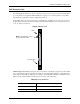

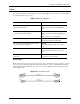
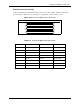

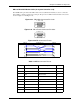
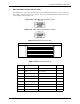
Table Of Contents
- Table of Contents
- About this Guide
- Chapter 1: Overview
- Chapter 2: Hardware Components
- Chapter 3: Installation
- Installation
- Connection
- Connect Power - CMS (14 slot), DC only)
- Connect Power - CMS960 (8 slot) and CMS240 (2 slot), DC only
- Install Power Cord Strain Relief (AC only)
- Power up the System (for AC unit)
- Prevent Electrostatic Discharge Damage
- Assign IP Address
- Install Software Upgrade via CMS Software Update Utility
- Chapter 4: Getting Started with Command Line Interface (CLI)
- Chapter 5: Working with SNMP
- Chapter 6: Call Detail Recording
- Chapter 7: System Alarms
- Chapter 8: Diagnostics/Maintenance
- Appendix A: Getting Acquainted with Tenor CMS in the VoIP Network
- Appendix B: Specifications/Approvals
- GLOSSARY
- INDEX
- WARRANTY
P/N 480-0005-00-15 2-34
Chapter 2: Hardware Components
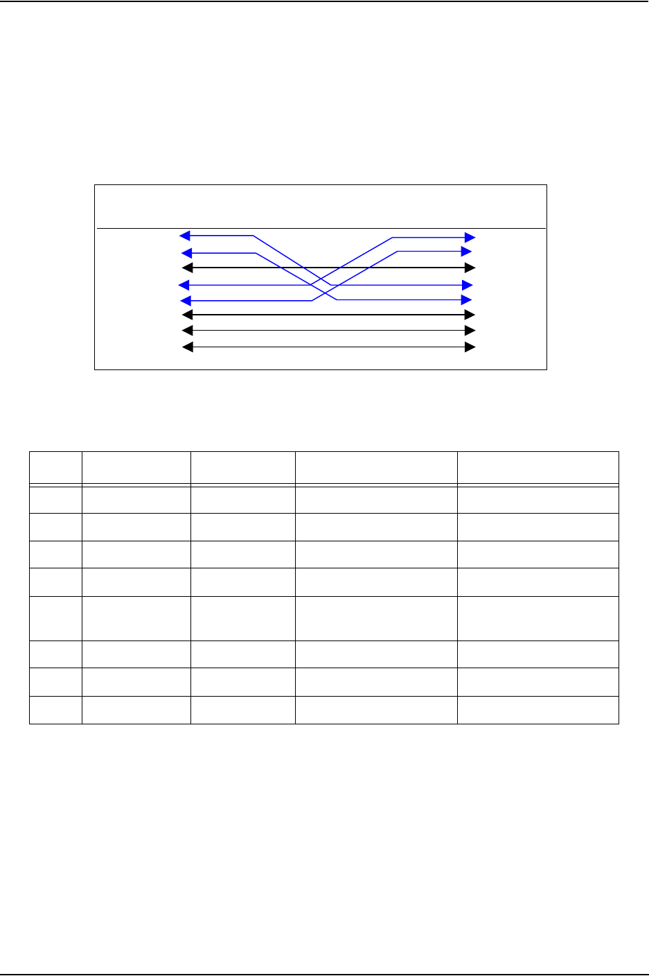
RJ-48 to RJ-48 Crossover Cable (T1/E1/DS1 WAN to Line Side)
An RJ-48 (T1/E1) crossover cable is used to connect Tenor CMS T1, E1 or DS1 WAN card to the Line Side
(PBX). Cable pinouts are provided below. If this cable is provided by Quintum, the color is red. The color
specifications are applicable to the RJ-48 crossover cable provided.
Figure 2-31 RJ-48 Crossover Cable Pinouts
Table 2-13 RJ-48 Connector Pinouts for T1/E1/DS1
Pin # Signal Definition Color for Connector 1 Color for Connector 2
1 RX ring Receive Ring White w/orange Blue
2 RX tip Receive Tip Orange White w/blue
3 RSVD Reserved -
4 TX ring Transmit Ring Blue White w/orange
5 TX tip Transmit Tip White w/blue Orange
6 RSVD Reserved - -
7 RSVD Reserved - -
8 RSVD Reserved - -
Pin # Connects to Pin #
1
2
3
4
5
6
7
8
1
2
3
4
5
6
7
8
Connector 1 Connector 2