HP 6G Virtual SAS Manager User Guide Abstract This guide provides information about using the HP Virtual SAS Manager application to configure and manage device zoning through HP 6Gb SAS BL switches. Both the Graphical User Interface (GUI) and Command Line Interface (CLI) are detailed.
© Copyright 2011 Hewlett-Packard Development Company, L.P. Confidential computer software. Valid license from HP required for possession, use or copying. Consistent with FAR 12.211 and 12.212, Commercial Computer Software, Computer Software Documentation, and Technical Data for Commercial Items are licensed to the U.S. Government under vendor's standard commercial license. The information contained herein is subject to change without notice.
Contents I Basic information and concepts.....................................................................6 1 About this document and 6G solutions......................................................8 About this document.............................................................................................................8 About solutions using the HP 6Gb SAS BL Switch.....................................................................8 2 Zone group concepts and device mappings.................
Prerequisites.................................................................................................................42 Obtaining new firmware................................................................................................42 Procedures...................................................................................................................43 Reset Storage Enclosure task................................................................................................
HP product documentation survey........................................................................................82 Index.........................................................................................................
Part I Basic information and concepts HP Virtual SAS Manager (VSM) is the software application used to configure HP SAS BL Switches, including tasks such as creating and managing hardware-based zone groups. These zone groups allocate resources for device load balancing purposes and for selectively allowing access to data. For planning purposes, zone groups and assignments can be pre-configured, even if server bays or drive bays are not yet populated.
Contents 1 About this document and 6G solutions..........................................................8 About this document.................................................................................................................8 About solutions using the HP 6Gb SAS BL Switch..........................................................................8 2 Zone group concepts and device mappings...................................................9 Zone group concepts...................................
1 About this document and 6G solutions About this document • This document assumes that all associated devices are physically installed and all required software components are installed on the servers. For hardware compatibility information, supported operating system versions, and supported Internet browser versions, see the SAS switch QuickSpecs. Review the QuickSpecs and verify that supported versions are installed on the devices.
2 Zone group concepts and device mappings Zone group concepts Zone groups allocate resources for device load balancing purposes and for selectively allowing access to data. For planning purposes, zone groups and assignments can be pre-configured, even if servers or disk drives are not yet installed. Types of zone groups: • Switch port zone groups—Group together one or more ports on the SAS BL Switch.
Device mappings for the c7000 BladeSystem enclosure: BladeSystem c-Class enclosure model Server type Mezzanine slot nl BladeSystem c-Class interconnect bay nl 1 3/4 2 5/6/7/8 1 3/4 2 5/6/7/8 3 5/6/7/8 1 3/4 2 5/6/7/8 3 5/6/7/8 4 5/6/7/8 5 3/4 7 5/6/7/8 Half height Full height c7000 Full height Double wide (BL680c G7) nl nl 10 Zone group concepts and device mappings
Part II VSM GUI
Contents 3 Getting started.........................................................................................14 Accessing the VSM GUI..........................................................................................................14 Page description.....................................................................................................................15 System status information.......................................................................................................
Diagnostic Log task.................................................................................................................47 Unit ID Light task....................................................................................................................47 Replicate Zoning Configuration task..........................................................................................47 6 Troubleshooting........................................................................................
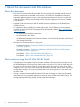
3 Getting started Accessing the VSM GUI VSM is accessed through the Onboard Administrator (OA) application of the BladeSystem c-Class enclosure in which the switch is installed. (For the minimum supported OA version, see the 6Gb SAS BL Switch QuickSpecs.) NOTE: To navigate directly to the VSM for a SAS switch, open the browser and enter the OA IP address or hostname followed by the interconnect variable. For example: https://10.10.1.
NOTE: In dual-domain switch configurations with two switches in the same interconnect bay row of the HP BladeSystem c-Class enclosure, both switches can process I/O, but the VSM utility can be active on only one of the switches. Switch management status (Active or Passive) is shown in the VSM navigation tree (not the OA navigation tree).
System status information A summary of system status information is displayed in the System Status section of the page. Critical—System is not operating properly Warning—Service is needed Informational—Helpful information Status alert details may be viewed in the following different ways: • To view all status messages: In the System Status section near the top-left of the VSM page, click View Status Alerts.
Online help Extensive online help is available. At any time, click the Help icon in the top right of the page. The following image is an example display of the online help. Performing tasks To perform any task in the VSM, observe the following key steps: 1. Select a tab at the top-left of the page. 2. Select a system component in the navigation tree on the left side of the page. 3. Select a task from the list on the right side of the page.
2. Go to the Zoning tab to create and assign zone groups. Key tasks include: a. Set the multi-initiator mode and, if multiple tape devices are included in the solution, enable port-splitting mode (optional). b. Create the zone groups. c. 3. • For deployments with shared SAS storage enclosures and tape libraries, create switch-port zone groups. • For deployments with zoned SAS storage enclosures, create drive-bay zone groups. Assign zone groups to servers.
Configuring P2000 G3 SAS MSA shared SAS storage enclosures (overview) Configuring shared SAS storage enclosures includes the following tasks, performed in sequence: 1. Enable Multi-initiator Mode. (“Advanced Settings task” (page 28)) 2. Optional: Enable Port-splitting Mode if multiple tape autoloaders or libraries are included in the solution. (“Advanced Settings task” (page 28)) 3. Create one or more switch-port zone groups. (“Create Zone Group task” (page 23)) 4. 5. 6.
Configuring MDS600 or D2600/D2700 zoned SAS storage enclosures (overview) Configuring zoned SAS storage enclosure includes the following tasks, performed in sequence: 1. Disable Multi-initiator Mode. (“Advanced Settings task” (page 28)) NOTE: If tape autoloaders/libraries or shared SAS storage enclosures are also connected to the switch and multiple server device bays will need access to the same switch-port zone groups, Multi-initiator Mode must be Enabled. 2. 3. 4. 5. 6.
4 Tasks in the VSM Zoning tab After selecting a component in the navigation tree, a unique task list for that component is displayed. The following table lists the tasks for each system component.
System component Available tasks Where documented More Information “More Information task” (page 22) Topology Map “Topology Map task” (page 22) More Information task To view detailed information about a device, select the device in the navigation tree and click More Information. Helpful hints: • The More Information task is available for each component in the navigation tree, in both the Zoning and the Maintain tabs.
Helpful hints: • To activate shading to more clearly show device relationships, click a device in the map. • To see what types of drives are installed in external storage enclosures, click the Drives drop-down arrow for that enclosure. Create Zone Group task Zone groups allocate resources for device load balancing purposes and for selectively allowing access to data. You can create the following types of zone groups: • Switch port zone groups—Group together one or more ports on the SAS BL Switch.
Select the following parameters: Name Type a name to assign to the zone group (must be unique, up to 16 characters, with no spaces). Zoning Mode Select Switch Port. Switch ports In the grid representing the switches, select the ports to be included in the zone group. To select a switch port, click an available (white) port. (The port status is automatically updated, changing the color from white to blue.) To clear a selection, click the selected (blue) port.
• • The following words may be displayed in the navigation tree by the zone group: ◦ Pending Save—until the configuration is saved. ◦ Unassigned—until a server device bay is granted access to the zone group. To assign this zone group to a server device bay, select the server device bay in the navigation tree and click Modify Zone Access.
selection, click the selected (blue) drive bay. (The bay status is automatically updated, changing the color from blue to white). • White=Selectable—Not yet assigned to a zone group and can be added to this zone group. • Blue=Selected—Selected in this session or already a member of this zone group. • Gray=Not Selectable—Assigned to a different zone group or attached to storage enclosures without port-based zoning capabilities. Can not be selected.
Delete task IMPORTANT: When using zoned SAS storage enclosures, before deleting a zone group, logical units associated with disk drives in that zone group must be deleted. If a deleted zone group has disk drives in bays that are configured as part of a logical unit, there may be I/O problems and the controller may send error messages to the system logs about an illegal drive movement. To delete an existing zone group, select a specific zone group to delete, and then click Delete.
Clear Configuration task To delete all user-defined zone groups and server device bay assignments, select the active switch in the navigation tree, and then click Clear Configuration. IMPORTANT: If external SAS storage enclosures are connected, before clearing the configuration, logical units associated with enclosures connected to the switch must be deleted.
Helpful hints: • In dual-domain switch configurations (two switches installed in the same interconnect bay row of the HP BladeSystem c-Class enclosure), a change to these settings on the active management switch is automatically propagated to the passive switch.
Helpful hints • Switch ports without attached storage enclosures can be assigned to a zone group. This allows you to pre-configure the zone groups and connect additional storage enclosures at a later time. • The following words may be displayed in the navigation tree by the zone group: ◦ Pending Save—until the configuration is saved. ◦ Unassigned—until a server device bay is granted access to the zone group.
the drive-bay zone groups and their assignments. This will help prevent accidentally assigning drive-bay zone groups to multiple servers or to servers that are not associated with the switch ports used by the zone group. • In a c7000 BladeSystem enclosure, when using a full-height blade with the P711m/P712m controller installed in mezzanine slot 3, the zone group must be assigned to the subsumed server device bay to allow the server to access the storage.
Switch ports In the grid representing the switches, select the ports to be included in the zone group. To select a switch port, click an available (white) port. (The port status is automatically updated, changing the color from white to blue.) To clear a selection, click the selected (blue) port. (The port status is automatically updated, changing the color from blue to white). • White=Selectable—Not yet assigned to a zone group and can be added to this zone group.
Creating and assigning drive-bay zone groups IMPORTANT: The maximum supported number of drive bay zone groups is 104. To create drive-bay zone groups, expand the display for the active switch in the navigation tree, select a specific Blade Port, and then click the Create and Assign Zone Group task button. . Select the following parameters: Name Type a name to assign to the zone group (must be unique, up to 16 characters, with no spaces).
• Blue=Selected—Selected in this session or already a member of this zone group. • Gray=Not Selectable—Assigned to a different zone group or attached to storage enclosures without port-based zoning capabilities. Can not be selected. Helpful hints: 34 • To expand or contract the display for each storage enclosure, click the arrow at the far right of the display. • In addition to the mouse, the tab, arrow keys, and space bar can be used to select or clear drives from the zone group.
5 Tasks in the VSM Maintain tab After selecting a device in the navigation tree, a task list for that device is displayed. NOTE: If a task is listed, but cannot be selected, system status conditions are not acceptable for that task to be performed. When this occurs, the cause is listed, so corrective action can be taken. The following table lists the available tasks.
The following tasks are common to most components and not described in this section.
• ◦ Back up the configuration for safekeeping. ◦ Refresh the VSM display to ensure displayed information is current. After updating firmware: ◦ Check the status of all solution devices for unexpected issues and correct as needed. IMPORTANT: When two SAS BL Switches are installed in the same interconnect bay row of a BladeSystem c-Class enclosure, they must run the same firmware version.
NOTE: In the HP Support websites: ◦ If you are not yet registered, click Register with the Business Support Center now to receive email notifications about firmware or hardware, driver and support alerts, advisories, and notifications. This alert notification system is a one-way broadcasting method to distribute important notices about HP products. ◦ Before clicking the Download button, click the title in the Description column to access important information about the update.
5. 6. Click Browse and navigate to the location of the previously-obtained firmware file. When downgrading to an older version of firmware than what is currently installed on the switch, check Force Downgrade. Click OK to begin the update. IMPORTANT: Do not interfere with or cancel the flashing process. Interrupting the flashing process may corrupt the firmware. 7. 8. Wait for a completion message to display. Open the maintenance window for restarting the switch: a.
5. Click Browse and navigate to the location of the previously-obtained firmware file. • When downgrading to a version of firmware that is older than what is currently installed on the switch, select Force Downgrade. • To update paired switches at the same time, select Update both Active and Passive switches. NOTE: By default, the Update both Active and Passive switches is selected. HP strongly recommends accepting this default, so that the chance of a firmware mis-match is reduced. 6.
11. Clear all temporary Internet files from the browser cache. 12. Log back in to VSM and confirm that the firmware installed successfully with no issues. 13. If Update both Active and Passive switches was not selected, repeat steps 2–12 to update firmware and then reset the additional switch 14. Close the maintenance window: a. Power on the server blades. b. Resume I/O. Reset Hardware task IMPORTANT: This task disrupts host I/O to the storage enclosures. Open a maintenance window before resetting devices.
NOTE: If the Update Storage Enclosures task is not selectable, consider the following: • Only supported storage enclosures can be updated. • All server blades that map to the storage enclosure must be powered off. • If the switch status is a value other than Active or Not Redundant, firmware updates are not allowed. • If the VSM GUI or VSM CLI is already processing a firmware update on a switch or storage enclosure, this task request cannot be processed.
Procedures 1. 2. 3. Obtain the latest firmware files and save to a temporary location on the host that has network access to the device you want to update. For more information, see “Obtaining new firmware” (page 42). Open the maintenance window for the update: a. Stop host traffic to the storage enclosures being updated. b. Power off all servers with access to the storage enclosures. From the workstation with access to both the firmware file and the BladeSystem c-Class enclosure, access the VSM.
13. Clear all temporary Internet files from the browser cache. For example, in Microsoft Internet Explorer 6, select Tools>Internet Options. In the Temporary Internet files section of the window, click Delete Files.... 14. Log back in to VSM and confirm that the firmware installed successfully with no issues. 15. Close the maintenance window: a. Power on the server blades. b. Resume I/O.
Helpful hints • Before resetting a storage enclosure, make sure that all I/O to the storage enclosure is halted. Power down all hosts with access to the storage enclosure and restart them after the reset is completed. • This task is required after updating storage enclosure firmware. • After the reset is complete, click the refresh icon to ensure that you are viewing the most recent status information. Confirm that the status of the storage enclosure is acceptable. Correct any issues as needed.
Force VSM Active task To force a switch to be the active switch from which configuration changes can be entered, select the switch in the navigation tree, and then click Force VSM Active. • In dual-switch configurations, this changes the switch status to VSM Active. • In single-switch configurations, this changes the switch status to Not Redundant. Helpful hints: • Switch status must be one of the following to use this feature: Mismatch, VSM Passive, or Not Configured.
Available parameters: Download Select this option to open a Save as window to navigate to the desired directory on the host system in which to place the event log file. NOTE: Print The default filename is eventlog.zip. Select this option to open a separate internet browser window to save or print the file using the browser's features.
Helpful hints To replicate the configuration settings, do the following: 1. Disconnect the failed storage enclosure from the switch. 2. Connect the replacement storage enclosure to the switch. The replacement storage enclosure must be the same model as the original one, with no existing zoning configuration information. 3. In the VSM, select the old-failed storage enclosure in the navigation tree, and then click Replicate Zoning Configuration. The enclosure will be labelled as offline. 4.
6 Troubleshooting Moving zone groups In some circumstances you may need to move zone groups from one server (origin) to a different server (destination). For example: • Server or other device failure requiring movement of zone groups to a different server • Server profile move Moving zone groups—zoned SAS storage enclosures When using zoned SAS storage enclosures, do the following to move zone groups from one server (original server device bay) to a different server (destination server device bay): 1.
Moving zone groups—shared SAS storage enclosures When using shared SAS storage enclosures, do the following to move zone groups from one server (original server device bay) to a different server (destination server device bay): 1. Open Virtual SAS Manager (VSM). 2. Identify all zone group assignments for the original server device bay. a. In the navigation tree, select the original server device bay and click Modify Zone Access. b. 3. 5. 6. 7.
Part III VSM CLI
Contents 7 Getting started.........................................................................................53 Accessing the VSM CLI............................................................................................................53 Command syntax....................................................................................................................55 Example command............................................................................................................
7 Getting started The VSM Command Line Interface (CLI) is an interactive command console that provides instant feedback and is functionally equivalent to the VSM graphical user interface (GUI). Commands are entered at a command prompt (=>) and must follow a specific, preset syntax. After a command is entered and executed, the returned results are instantly displayed on the CLI console.
3. Launch an SSH utility on a PC that can access the same LAN as the BladeSystem c-Class enclosure. The following example illustrates using the PuTTY utility. a. b. c. 4. Enter the VSM CLI IP addresses in the Host Name (or IP address) field. Verify that the SSH radio button is selected. Click Open. The SSH shell opens. When prompted, enter an OA username and password with administrative privileges.
Command syntax A typical VSM CLI command string consists of three variables: a target device, a command, and one or more clarifying parameters. The syntax of a VSM CLI command line is as follows: command [parameter=OPTION_A|OPTION_B] [parameter] The following conventions apply to all VSM CLI command strings: • A basic command string includes identifying information about the target, along with a command word and clarifying parameters, if required or desired. • Commands are not case sensitive.
Device Target syntax Supported parameters External storage enclosure connected to a SAS switch blade storageenclosure portbox storageenclosure enclosureid Storage enclosure drive bay (must be storageenclosurebay preceeded by a blade enclosure or switch portboxbay target) Zone group (must be preceeded by a blade zonegroup name enclosure or switch target) Example target entries in a command string: => bladeenclosure chassisname=ABC => bladeport id=6 => switc
Command syntax Command description replicate Replicate zoning configuration settings from an old, failed external SAS storage enclosure onto its newly-connected replacement. rescan Update system status. reset Restart the switch VSM software. This command is used after flashing firmware (on switches or attached storage enclosures) or updating network settings. retrysave Retry the saveupdate command. saveupdate Process (commit) all commands entered since the last startupdate command.
Executing commands Configuration changes are made on a transaction basis. To prevent conflict with another administrator making changes through a different VSM GUI or CLI session, you must indicate when you are starting, saving, or clearing your changes by using the following commands: startupdate saveupdate clearupdate • Before entering add, create, delete, or modify commands, enter startupdate to start the transaction.
8 Getting help The help and the show commands provide detailed information about system devices and how to use VSM CLI commands to perform configuration tasks. The help command The help command displays information about a VSM CLI command, including a definition, required syntax, available parameters, the number of characters for a command option value, or a list of allowed/disallowed characters.
The show command The show command displays information about a device. Use this command to view the current status of a device and its configuration. Syntax show [config] [detail] Parameters config Forces the display to include configuration information about the specified target device. detail Forces a more detailed display, including information for other items such as zone groups. Example 1: The following example displays the results of the show command for a blade enclosure.
Example 3: The following example displays the results of the show command for an HP BladeSystem enclosure when the config parameter is specified. => bladeenclosure location=local show config Blade Enclosure at R20_top (SN: USE104690F) Switch in Interconnect Bay: 5 Management Software Version: 2.0.1.
9 Performing common tasks Example commands and system responses shown in this section are provided only as a general reference and may differ from the commands used and system responses in your environment. For more information on the available options for each command, see VSM CLI online help.
Enabling or disabling multi-initiator mode and port splitting The advance command controls two advanced parameters: • Multi-initiator mode—Controls whether multiple initiators (server device bays) can access the same zone group. When this option is selected, a zone group can be assigned to multiple BladeSystem server device bays. Multi-initiator mode should be enabled when shared SAS devices, such as the P2000 G3 MSA and tape devices are connected to the switch.
Creating zone groups Zone groups allocate resources for device load balancing purposes and for selectively allowing access to data. You can create the following types of zone groups: 64 • Switch-port zone groups—Group together one or more ports on the SAS BL Switch. Server device bays assigned this type of zone group have access to the storage enclosures or tape devices connected to the ports included in the zone. This type of zone group is for shared SAS devices.
Creating a switch-port zone group Used with shared SAS storage enclosures or tape autoloaders or libraries, switch port zone groups are comprised of one or more SAS ports on the switch. Server device bays assigned this type of zone group have access to the array enclosures or tape devices connected to the ports included in the zone group. Access to specific LUNs in the array enclosures must be controlled through the storage management utility for the array enclosure.
Success NOTE: Entering a range of port numbers is not supported. Each port must be entered, separated by a comma. 3. [Optional] Verify that the zone group was created as intended. For example, use one of the following commands: => switch loc=local port all show detail => switch loc=local zg OpenZone show The display of this example is abbreviated, retaining key details. The display shows information for the switch installed in interconnect bay 5, and that port 4 is included in zone group named Ports_1.
Creating a drive-bay zone group Used with zoned SAS storage enclosures such as the MDS600 and D2600/D2700, drive-bay zone groups group together disk drive bays, which can be chosen from one or more MDS600 drawer or D2000 disk enclosures. Server device bays assigned this type of zone group have access to the disk drive bays included in the zone, as if they were directly connected to those servers.
2. Create the zone group. This example shows how to create a zone group named zone5, using drive bays 29 through 35 on an MDS600 storage enclosure connected to port 1 of a switch in interconnect bay 5. => switch loc=local startupdate Success => switch loc=local create type=zg name=zone5 seb=51:1:29,51:1:30,51:1:31, 51:1:32,51:1:33,51:1:34,51:1:35 Success => switch loc=local saveupdate Success 3. [Optional] Verify that the zone group was created as intended.
Assigning a zone group to a server device bay Server device bays cannot access external storage connected to the switch until assigned a zone group. IMPORTANT: • For an existing zone group, when changing the assignment to move the zone group to a different server device bay, you must first stop all associated I/O with the zone group and power off the server blades. After completing the assignments and saving all changes in the VSM, restart the servers and resume I/O.
Success This example shows how to assign the zone group, zone5, created in “Creating a drive-bay zone group” (page 67) to BladeSystem device server bay 5. => switch loc=local startupdate Success => bladeport id=5 add zg=zone5 Success => switch loc=local saveupdate Success 3. [Optional] Verify that the zone group was assigned as intended.
Capturing the configuration After initially configuring the switch or after making changes to an existing configuration, HP strongly recommends backing up the configuration for safekeeping. NOTE: The configuration can be backed up to an FTP server or temporarily saved to the switch and then transferred to a different location using a secure copy tool. Example secure copy tools include pscp.exe for Windows and scp for Linux. Syntax capture [file=] [ftp ipaddr=
Inputting or restoring the configuration To restore a previously saved configuration of a switch, use the following command description: NOTE: A configuration can be installed on a switch directly from an FTP server or by using a secure copy tool to temporarily save the configuration to the switch and then install it. Example secure copy tools include pscp.exe for Windows and scp for Linux. Syntax input [file=] [ftp ipaddr=
Flashing switch firmware To update firmware on a switch, use the following command description: Syntax • • flash [file=] [username=] [password=] [forced] Before updating switch firmware: ◦ Schedule a time for the installation. Because firmware updates require that the switch be restarted, firmware must be installed during a scheduled maintenance window.
=> switch loc=local flash file=filename.img 3. When the update is complete, reset the switch. Recommended procedures vary for single-domain and dual-domain environments. For information on resetting switches, see “Resetting the VSM software, the switch or attached storage enclosures” (page 76). Example 3: This example demonstrates updating firmware on both switches at the same time. 1.
Flashing storage enclosure firmware To update firmware on an attached zoned SAS storage enclosure such as the MDS600, D2600, or D2700, use the following command description: Syntax • • flash [file=] [username=] [password=] [forced] Before updating firmware: ◦ Schedule a time for the installation. Because firmware updates require that the storage enclosure be restarted, firmware must be installed during a maintenance window.
Resetting the VSM software, the switch or attached storage enclosures IMPORTANT: This task disrupts host I/O to the storage enclosures. Open a maintenance window before resetting devices.
10 Creating and executing CLI scripts If desired, create and execute scripts to automatically perform a task or series of tasks. CLI scripting varies depending on operating systems, but the information provided in this section describes using the Plink SSH utility in a Windows environment. Creating and executing a script in a Windows environment includes the following steps: 1. Create a .txt file with each command to execute, using exact command syntax. 2. Create a .
Part IV Support and other resources
Contents 11 Support and other resources.....................................................................80 Contacting HP........................................................................................................................80 Subscription service............................................................................................................80 Related information.................................................................................................................
11 Support and other resources Contacting HP For worldwide technical support information, see the HP support website: http://www.hp.
Prerequisites Prerequisites for using this product include: • Physically installing the BladeSystem c-Class enclosure and any servers, SAS controllers, SAS switch blades, and storage blades. • Physically installing the external SAS storage enclosures. • Connecting all cables using a supported cabling scheme. For information about these tasks, see the BladeSystem and device user documents.
HP product documentation survey Are you the person who installs, maintains, or uses this HP storage product? If so, we would like to know more about your experience using the product documentation. If not, please pass this notice to the person who is responsible for these activities. Our goal is to provide you with documentation that makes our storage hardware and software products easy to install, operate, and maintain.
Index A accessing the CLI, 53 accessing the VSM GUI, 14 advance CLI command, 63 Advanced Settings GUI task, 28 assigning zone group to server CLI, 69 GUI, 30 C capture CLI command, 71 Capture Configuration GUI task, 36 Clear Configuration GUI task, 28 Clear VSM Event Log task, 47 clearupdate CLI command, 58 Command Line Interface (CLI) accessing, 53 advance command, 63 assigning zone group to server, 69 capture CLI command, 71 capturing the configuration, 71 command syntax, 55 command variable, described,
Maintain tab, 35 Merge Sub-Ports task, 29 Modify task, 27 Modify Zone Access task, 30 More Information command, 22 Multi-initiator task, 28 Network Settings task, 45 Replicate Zoning Configuration task, 30, 47 Reset Hardware task, 41 Reset Management Software task, 41 Reset Storage Enclosure task, 44 SNMP Settings task, 45 Split Port task, 28, 29 Update Storage Enclosure Firmware task, 43 Zoning tab, 21 H help obtaining, 80 help CLI command, 59 HP technical support, 80 I input CLI command, 72 Input Config
Replicate Zoning Configuration, 30, 47 Reset Hardware, 41 Reset Management Software, 41 Reset storage enclosures, 44 SNMP Settings, 45 Split Port, 28, 29 Topology Map, 22 Update Storage Enclosure Firmware, 43 technical support HP, 80 service locator website, 80 text symbols, 81 Topology Map GUI task, 22 typographic conventions, 81 U Update Storage Enclosure Firmware GUI task, 43 V VSM Event Log task, 46 W websites HP , 80 HP Subscriber's Choice for Business, 80 product manuals, 80 Z zoned SAS storage en