OWNER'S MANUAL __________________ PRINT MASTER 700 SERIES PRINTER CONTROLLERS 706A 706C 708C 710C 706D 708D 706E 708E 710E 708F 710F BayTech publication #U140E045-05
Dear Customer, Thank you for selecting a BayTech Print Master printer controller. The data provided in this Owner's Manual explains the various ways you can operate your unit and configure it to your own computer system. We suggest that you read this manual carefully before attempting to install Print Master and that you place special emphasis on correct cabling and configuration. If you have any problems with your installation, please contact a BayTech applications engineer for assistance.
The information contained in this document is subject to change without notice. Copyright 1993 by Bay Technical Associates, Inc. IBM PC, IBM PC/AT, IBM PC/XT and IBM PS/2 are products of International Business Machines Corporation. Hewlett-Packard LaserJet is a product of the Hewlett-Packard Company. Wordperfect is a product of Wordperfect, Inc. WordStar is a registered trademark of MicroPro International Corp. Windows is a registered trademark of Microsoft Corp.
TABLE OF CONTENTS 1 GENERAL INFORMATION............................................... 1 2 SPECIFICATIONS ............................................................ 3 3 QUICK REFERENCE ....................................................... 6 4 INSTALLATION .............................................................. 10 4.1 4.2 4.3 4.4 4.5 5 10 10 12 12 13 CABLING ........................................................................ 15 5.1 5.2 5.3 6 UNPACKING..............................
6.2 PRINTER SHARING OPERATING PROCEDURE 24 6.2.1 SHARING A SINGLE PRINTER................ 6.2.2 SPECIFIED SHARING OF MULTIPLE PRINTERS ................................................ 6.2.3 CONTENDING FOR MULTIPLE PRINTERS ................................................ 6.2.4 BUFFERING OF PRINT DATA ................. 6.2.5 BEGINNING AND ENDING A PRINT JOB 6.2.6 BUFFER CLEARING................................. 6.2.7 MINIMUM SIZE PRINT JOB...................... 6.2.8 PORT SELECTION METHODS ................
7.1.6 MODELS 706A AND 708A - PROGRAM PRINTER SELECT CODE ........................ 7.1.7 MODELS 706A AND 708A - SET PRINTER SELECT MODE ........................ 7.1.8 MODELS 706A AND 708A - SET FORM FEED MODE ............................................. 7.1.9 MODELS 706A AND 708A - PROGRAM HEADER PAGE MESSAGE...................... 7.1.10 MODELS 706A AND 708A - EXIT............. 7.2 45 46 46 47 47 ALL 700C MODELS - CONFIGURATION PROCEDURE ...................................................... 48 7.2.
.3 ALL 700D, 700E, 700F MODELS CONFIGURATION PROCEDURE ....................... 60 7.3.1 ALL 700D, 700E, 700F MODELS - MAIN CONFIGURATION MENU......................... 7.3.2 ALL 700D, 700E, 700F MODELS STATUS .................................................... 7.3.3 ALL 700D, 700E, 700F MODELS -SET SERIAL PORT CONFIGURATION............ 7.3.4 ALL 700D, 700E, 700F MODELS -CHANGE PORT LOGICAL NAME ........... 7.3.5 ALL 700D, 700E, 700F MODELS - SET PORT ASSIGNMENT................................ 7.3.
APPENDIX A RECOMMENDED CABLING ......................................... 78 A.1 A.2 A.3 A.4 A.5 BETWEEN IBM PC, IBM XT, IBM PS/2 AND PRINT MASTER (DB-25) ............................ BETWEEN IBM AT AND PRINT MASTER (DE-9)................................................................... BETWEEN PRINT MASTER AND HEWLETT PACKARD LASERJET ...................... BETWEEN PRINT MASTER AND ANY CENTRONICS PRINTER ............................ 700C MODELS - MODULAR CABLING...............
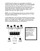
The BayTech 700 Series Print Master is a flexible, intelligent device that connects between your computers and peripherals allowing the computers to share the peripherals, including expensive plotters and laser printers. All models come in a self-contained desk-top unit or with a rack mount. Print Master comes standard with a 1 MB buffer which is optionally available up to 2 MB.
In addition to port assignment, you may program the following features to meet the need of your application: the individual serial port configuration (baud rate, word size, stop bits, parity, and XON/XOFF), the Port Logical Names, the Input Inactivity Timeout, the Printer Select Code, the Printer Select Mode, the Form Feed Mode, and the Header Page Message. Programming of these features is easily accomplished via the menu-driven configuration mode, and all changes are saved in non-volatile memory.
2. INTERFACE: Serial ports: Asynchronous EIA-232C (CCITT V.24), -12v mark, +12v space. Full duplex communication. Parallel ports: Centronics protocol. TRANSMISSION: Serial ports - asynchronous; full duplex communication; Parallel ports - maximum 30,000 characters per second on the 706A and 708A. Up to 5000 characters per second on all other models. STANDARD FACTORY-SET POWER-UP DEFAULT CONFIGURATION: Serial ports: Baud rate: 9600. Word size: 8. Stop bits: 1. Parity: None. XON/XOFF: Off.
USER-PROGRAMMABLE CONFIGURATION: Reconfigurable in menu-driven mode through configuration port. Saved in non-volatile memory to become the new power-up default configuration. Serial ports: Baud rate: 110, 135, 300, 600, 1200, 2400, 4800, 9600, 19200. Other rates optional. Word size: 5, 6, 7 or 8 bits. Parity: Even, odd or none. Stop bits: 1, 1 1/2 or 2. XON/XOFF: On or off. Port logical name: 16 characters. Input inactivity timeout: 1 to 200 seconds or no timeout.
POWER: 115 VAC, 50/60 Hz., .3A. Optional 230 VAC, 50/60 Hz., .2A. ENVIRONMENT: 0 degrees to 55 degrees C temperature; 5% to 95% humidity. DIMENSIONS: 10 1/8w x 8d x 3h inches. WEIGHT: 6 pounds. INDICATORS: 1 green power LED; 6, 8 or 10 red, port-activity LEDs. CONNECTORS: Shielded on all ports. Serial ports - DB-25 female DCE connectors. Parallel ports - DB-25 female connectors. RJ-45 connectors available on the 706C, 708C, and 710C. HANDSHAKING: Parallel ports - Busy (pin 11).
This section provides basic set up instructions for those knowledgeable in computer equipment installation. We will refer to specific sections in this manual for more in-depth instructions on installation operation, and configuration. Please review the following procedure: Step Instructions 1 Determine what model Print Master you are installing. The model number is written on the front panel as shown below for the model 708A.
Step Instructions connect to ports assigned as printer. All ports are flexible except as noted below (i.e., ports may be configured as computer or printer).
Step Instructions A. Serial Ports Serial ports on Print Master are DCE. Therefore, straight cabling is required between the computer's serial port and Print Master's serial port. A straight cable is also required between Print Master's serial port and the serial port of a printer or plotter. B. Parallel Ports A straight through 25 pin parallel DB-25 male to DB-25 male cable is required to connect the parallel port of a computer to a parallel port of Print Master.
Step Instructions To print from a serial port of your PC, you must first redirect the parallel output to the serial port via the DOS command C:>MODE LPTx:=COMy:, where x and y are the port designation (e.g., LPT1:=COM1:). You must also configure your PC's serial port to communicate at parameters that match Print Master. This is done via the DOS command C:>MODE COMy: 9600,n,8,1,p, where y is the com port number of your PC. This MODE command assumes you are using factory default values.
After opening the box, check the packing list that comes with Print Master to ensure that you have received all components. Also check the unit to make certain that it did not receive damage during shipping. BayTech provides utility software to assist you in configuring the Print Master. There are three peripheral selection programs included to provide easy device selection from text mode, graphics mode, or Windows.
To run INSTALL, use the following procedure: 1. Insert the software utility diskette into drive A (or drive B) and from the prompt type INSTALL followed by . 2. A menu titled "Drive & Directory Definitions" will appear on your screen. This menu will display the Source Drive, Destination Drive, and Destination Directory. The Source Drive is the floppy drive where the diskette is inserted. The Destination Drive is the drive where the expanded files will be copied to (default is drive C).
The Print Master requires 115 VAC, 50/60 Hz. power and comes with a three-prong power cord. Do not attempt to operate the unit with a two-prong socket or adapter. 230 VAC, 50/60 Hz. is optional. The Print Master powers-up when you press the power switch on the back of the unit to "ON" or "1". Power-on is indicated on the front panel by the illuminating of a green LED. CAUTION: Do not attempt to make any internal changes.
This section provides instructions on how to set up your PC to work with Print Master with respect to the BayTech software (if you intend to use it) and special considerations when connecting your PC in serial. If you intend to use the RAMEXEC or RAMTSR hot key programs to select between multiple peripherals, you would typically add the command C:>RAMEXEC or C:>RAMTSR to your PC's AUTOEXEC.BAT file.
You will also need to change the serial port configuration of your PC's com port to match that of the Print Master. If using the Print Master's factory default serial configuration, this is accomplished via the DOS command C:>MODE COMy: 9600, N, 8,1,P where y is the number of the appropriate com port. This command should be part of your AUTOEXEC.BAT file. Alternatively, you may use the SMODE.EXE utility to operate at speeds greater than 9600 bps.
Please see Section 5.1 for parallel port cabling information, Section 5.2 for DB-25 serial port cabling information, or Section 5.3 for RJ-45 cabling. Appendix A provides recommended cabling pinouts. Parallel ports on Print Master have DB-25 female connectors. A straight, DB-25 male-to-male cable is required between each IBM PC computer (or compatible) and a parallel port on Print Master.
IMPORTANT: Before you proceed with cabling, you must know whether the devices that you will connect to Print Master are DTE (Data Terminal Equipment) or DCE (Data Communication Equipment). The following devices are generally DTE: terminals, printers, and computers like the IBM PC. The following devices are DCE: modems and some computers. If your device transmits data on Pin 2 and receives data on Pin 3, it is DTE.
DTE ports use the following signals for communication: DTE PORT PIN/SIGNAL DEFINITION Pin Signal (EIA-232) Direction Description 1 PGND --- 2 Tx Output 3 Rx Input 4 RTS Output 5 CTS Input Clear To Send: Input handshake line. Must be positive voltage before DTE device will transmit data. 6 DSR Input Data Set Ready: Input handshake line. Must be positive voltage before DTE device will transmit data.
PRINT MASTER - DCE MALE DB-25 DTE DEVICE MALE/FEMALE DB-25 1 PGND 2 TXD 3 RXD 4 RTS 5 CTS > 6 DSR > 7 SGND 8 DCD 20 DTR < > < > < PGND 1 TXD 2 RXD 3 RTS 4 CTS 5 DSR 6 SGND 7 DCD 8 DTR 20 FIGURE 2 PRINT MASTER - DCE MALE DB-25 1 PGND 2 TXD 3 RXD 4 RTS 5 CTS 6 DSR 7 SGND 20 DTR < < < DCE DEVICE MALE DB-25 < < < PGND 1 TXD 2 RXD 3 RTS 4 CTS 5 DSR 6 SGND 7 DTR 20 FIGURE 3 NOTE: Please refer to Appendix A for recommended cabling b
! " # $ The EIA-232 serial ports of the Print Master Models 706C, 708C, or 710C may have RJ-45 modular connectors. This section will address the cabling and modular adapter information required for 700C models with RJ-45 modular connectors. BayTech has a complete line of RJ-45 adapters and cables that will make your installation quick and trouble free. Call your dealer or BayTech for order information.
Figure 4: RJ-45 Receptacle Figure 5: RJ-45 Plug Please see Appendix A.5 for modular adapter pinout and cabling information. This section discusses the various user-programmable configurations (Section 6.1), printer sharing operation (Section 6.2), the LED indicators (Section 6.3), and data flow control (Section 6.4).
# % # Individual ports on Print Master may be configured as computer or printer via the Number of Printers/Port Assignment. Computers connect to computer ports. Printers and plotters connect to printer ports. On all models, a minimum of one port must be assigned as a printer port and a minimum of one port must be assigned as a computer port.
# To select a printer in multiple printer applications, the computer sends the Printer Select Code (which consists of any ASCII character string numbering from one to eight characters) followed by the desired printer port number. The Printer Select Code is trapped by Print Master if it is valid and not passed to the printer.
# NOTE: This section is not applicable to the 706A or 708A models. Print Master will translate for serial devices using different configurations. You may set the baud rate, word size, stop bits, parity and XON/XOFF for each individual serial port. The available values for these parameters are listed in Section 2 (Specifications). Factory default configuration on all serial ports is 9600 baud rate, 8 word size, 1 stop bit, no parity and XON/XOFF disabled.
" # # You may configure Print Master to print a programmable message and the logical name of the source computer on a separate sheet of paper before printing any other data. You may enable or disable the Header Page Message for each individual computer port. Factory default is: This print job is for:, with the Header Page Message disabled.
Please see the table below for a quick reference to the printer sharing operating procedure. PRINTER SHARING QUICK REFERENCE Item See Section Sharing a single printer 6.2.1 Specified sharing of multiple printers 6.2.2 Contending for multiple printers 6.2.3 Buffering of print data 6.2.4 Beginning and ending a print job 6.2.5 Buffer clearing 6.2.6 Minimum size print job 6.2.7 Port selection methods 6.2.8 Full duplex communication 6.2.9 Plotter sharing hints 6.2.
# To select a specific printer in multiple printer applications, you must send a specific printer select sequence which consists of the Printer Select Code (factory set is $PRINTER) followed by the desired printer port number. The Printer Select Code and port number are trapped if valid and not passed to the printer. The printer port number then becomes the printer assignment number for your computer port.
There are two modes for sending the Printer Select Code. In Printer Select Mode 2 (printer selection anytime while printing), Print Master looks for the Printer Select Code any time. If no Printer Select Code is received, the data will be routed to the default printer. In Printer Select Mode 1 (printer selection at beginning of printing), Print Master looks for the start of the Printer Select Code in the first 16 characters received.
When a user sends a print job, the data is stored in Print Master's spooling buffer (1 MB standard, available with 2 MB on 700C, 700D and 700E models; available with up to 4 MB on 700A models). All users may simultaneously send data to this dynamically allocated buffer. Therefore, the entire buffer could be occupied by data from one user if only one user is active or the buffer could be simultaneously distributed to all users.
4. The computer sends the Printer Select Code followed by a printer port number. If the port number is the same number as that of the current print job, this will indicate the end of the current print job, and the next print job will be routed to the same printer. If the port number is a different number from that of the current print job, this will indicate the end of the current print job, and the next print job will be routed to the newly selected printer.
If you wish to clear a print job is sent in error, you must send the clear buffer sequence which consists of the Printer Select Code followed by CLR. This command will only affect print jobs originated by your computer. Print jobs in the buffer from other computers are not affected. The clear buffer sequence will clear the most recent print job sent to Print Master from your computer.
" # BayTech provides utility software which allows you to conveniently select between peripherals for IBM DOS and Microsoft Windows applications. Port selection is as easy as activating hot keys or by using a mouse. Please see Section 4.2 for more information. There are alternative methods to peripheral selection. One method is to make the port select sequence the first characters of the text. These characters will be trapped by Print Master and not sent to the printer.
Programs such as Word Perfect and WordStar typically send a printer initialization string before any data. You may imbed the port select sequence in this string to select a printer. For example, Word Perfect allows you to edit the printer definition file for a specific printer by using the PTR command. The port select sequence for the Print Master would typically be inserted prior to any escape codes for the printer.
It is still possible to plot dynamically through Print Master if required. When plotting in this fashion, you would probably need to increase the input inactivity timeout value to a higher number than factory default (20 seconds). Plotting dynamically would not allow you to utilize the buffering capabilities of Print Master because the data stream from the computer is not continuous.
# # # COMPUTER-TO-PRINT MASTER-TO-PRINTER COMMUNICATION When a computer transmits data to a printer through a Print Master computer port, the data is received and stored in the buffer which in turn retransmits it to the printer through a printer port.
PRINT MASTER-TO-COMPUTER COMMUNICATION NOTE: Print Master will provide full duplex communication between a computer and printer which are connected through the unit. This section is applicable only when a device that is connected to a printer port is sending data back to a device connected to a computer port. When Print Master is sending data to a computer through a computer port and the computer cannot receive any more data, Print Master will expect to see a low on the DTR line.
) %) # # COMPUTER-TO-PRINT MASTER-TO-PRINTER COMMUNICATION When a computer transmits data to a printer through a Print Master computer port, the data is received and stored in the buffer which in turn retransmits it to the printer through a printer port.
PRINT MASTER-TO-COMPUTER COMMUNICATION NOTE: Print Master will provide full duplex communication between a computer and printer which are connected through the unit. This section is applicable only when a device that is connected to a printer port is sending data back to a device connected to a computer port. When Print Master is sending data to a computer through a computer port and the computer cannot receive any more data, Print Master will expect to see a low on the DTR line or receive an XOFF.
Configuration changes are made through the master configuration port which is the highest numbered port on all models. Print Master will transmit configuration menus to the serial device connected to the master configuration port on all models except the 706A and 708A. The 706A and 708A will print out configuration menus on a parallel printer connected to Port 1 as described in Section 7.1. If you are configuring a 700C unit, please see Section 7.2.
All ports on the Print Master 706A or 708A must be inactive (i.e., only the green power LED should be illuminated). With the PARSEND or MS BASIC program loaded on your PC, send from the keyboard Control-T followed by capital C. These characters will not print on the printer. The Model 706A or 708A will respond with the main configuration menu which should print out on your printer. When configuration mode is been accessed, all the red LEDs on the front panel will illuminate.
" Print Master 706A and 708A will respond to the receiving of Control-T and C by sending to the printer on Port 1 the following identification block and a menu of the configuration options available: Bay Technical Associates Model 706A Print Master Copyright 1989 Revision 3.00 Total Memory : 1024K Bytes Status.......................................1 Change Logical Name..........................2 Set Input Inactivity Timeout.................
" By responding to the Enter Request: message at the end of the main configuration menu with "1" (Status), you may review the current configuration status of the 706A and 708A. Print Master will respond with: Current Printer Port Configuration Port 1 Logical Name Device A Prnt Assn 1 Current Computer Port Configuration Port 2 3 4 5 6 Logical Name Device B Device C Device D Device E Device F Prnt Assn 0 0 0 0 0 Press any Key to continue Input Inactivity Timeout is...
" # By responding to the Enter Request: message at the end of the main configuration menu with "2" (Change Logical Name), you may change the identifying name for the device on each port. Print Master 706A and 708A will respond with: Enter Port Number (1 to 6, 0=Exit), CR: Type the number of the desired port followed by .
" & By responding to the Enter Request: message at the end of the main configuration menu with "3" (Set Input Inactivity Timeout), you may set the input inactivity timeout. Print Master will automatically disconnect the computer if no characters are received from the computer for the specified timeout period. Print Master 706A and 708A will respond with: Input Inactivity Timeout is...............20 seconds Enter Timeout (0 to 200), hit return.....
" By responding to the Enter Request: message at the end of the main configuration menu with "4" (Set Number of Printers), you may change the number of computer ports and printer ports. Print Master 706A will respond with: Number of printers is....................1 Enter Number of Printers (1 to 5)........: Enter the number of printers that you desire. NOTE: Print Master 708A will show the Number of Printer from 1 to 7.
" By responding to the Enter Request: message at the end of the main configuration menu with "5" (Set Printer Select Code), you may change the Printer Select Code to a user-defined code. The Printer Select Code consists of any character string from 1 to 8 ASCII characters. Print Master will respond with: Printer Select Code is......................$PRINTER Enter Printer Select Code (0 to 8 Chrs, Hit Return)...................
" By responding to the Enter Request: message at the end of the main configuration menu with "6" (Set Printer Select Mode), you may change the method of selecting printers. Print Master 706A and 708A will respond with: Select Printer At the Beginning of Printing Only...1 Anytime While Printing..............2 Printer Select Mode is..............2 Enter Printer Select Mode...........: Enter the new Printer Select Mode.
( " # By responding to the Enter request: message at the end of the main configuration menu with "8" (Program Header Page Message), you may enable or disable this message and program its content. Print Master will respond with the following: Header Page Message is (OFF): This print job is for: Enter Header Page Message (0 to 80 chrs, Ctrl C = Terminate): Enter the new message, followed by Control-C.
All configuration changes must be made through the master configuration port. This master configuration port has access to all options of the configuration mode. Please use the following procedure to configure your Print Master 700C model: 1. Connect a dumb terminal (or a PC running a terminal emulation program) to the master configuration port which is Port 6 on the 706C, Port 8 on the 708C, Port 10 on the 710C.
If you do not have a dumb terminal or a terminal emulation program, BayTech supplies a utility diskette which includes software to put an IBM PC or compatible into a terminal mode. See Section 4.2 for instructions to obtain the software (TERM.EXE) by running the INSTALL.EXE program if you have not already done so. Once you have obtained TERM.EXE, use the following procedure: 1.
3. Refer to the upper right hand corner of the screen for Handshaking line status. RTS, CTS, DSR, and DTR should all be HIGH. The DCD line is not looked at by the terminal emulation program therefore its status can be ignored. If these signals are not high at this point, check to ensure the correct cable is connected. 4. Depress function key: F1. NOTE: The F1 key in TERM sends the character sequence Control-T (14 Hex) followed by the capital C character (43 Hex).
By responding to the Enter Request: message at the end of the main configuration menu with "1" (Status), you may review the status of the current configuration of Print Master.
By responding to the Enter Request: message at the end of the main configuration menu with "2" (Set Serial Port Configuration), you may change the serial configuration of each port (i.e. baud rate, word size, stop bits, parity, and XON/XOFF). Each port may be configured individually. This allows Print Master to translate for devices using different configurations. You may also assign or change the Logical Name for each port.
You may now reconfigure Port 5 by selecting the appropriate option from the menu. For example, to change the baud rate to 2400 baud, send character "2" (Set baud rate).
CAUTION: If Y is sent before changing the configuration device to the new configuration (baud rate or parity), Print Master will not receive the Y response. However, you will be locked out of Print Master. If this occurs, recycle Print Master power. Print Master's configuration will default back to the last saved configuration. You must then re-enter configuration and re-save the configuration of the configuration port.
& By responding to the Enter Request: message at the end of the main configuration menu with "3" (Set Input Inactivity Timeout), you may set the input inactivity timeout. Print Master will automatically disconnect the computer if no characters are received for the specified timeout period. Print Master will respond with: Timeout is................................20 seconds Enter Timeout (0 to 200), hit return.....
By responding to the Enter Request: message at the end of the main configuration menu with "4" (Set Number of Printers), you may change the number of printers. IMPORTANT: The lowest-numbered ports on the 706C, 708C and 710C Print Masters are reserved as printer ports. For example, the Model 706C has a total of six available ports of which as many as five may be printer ports with the remainder reserved as computer ports.
By responding to the Enter Request: message at the end of the main configuration menu with "5" (Program Printer Select Code), you may change the Printer Select Code to a user-defined code. The Printer Select Code consists of any character string from 1 to 8 ASCII characters. Print Master will respond with the following: Printer Select Code is......................$PRINTER Enter Printer Select Code (0 to 8 Chrs, Hit Return=Terminate).........
By responding to the Enter Request: message at the end of the main configuration menu with "6" (Set Printer Select Mode), you may change the method of selecting printers. Print Master will respond with: Select Printer At the Beginning of Printing Only...1 Anytime While Printing..............2 Printer Select Mode is..............2 Enter Printer Select Mode...........: You should then enter the Printer Select Mode you want.
( # By responding to the Enter request: message at the end of the main configuration menu with "8" (Program Header Page Message), you may enable or disable this message and program its content. Print Master will respond with: Header Page Message is (OFF): This print job is for: Enter Header Page Message (0 to 80 chrs, Ctrl C = Terminate): Enter the new message followed by Control-C.
! ! All configuration changes must be made through the master configuration port. This master configuration port has access to all options of configuration mode. Please use the following procedure to configure your Print Master 700D, 700E, or 700F model: 1.
If you do not have a dumb terminal or a terminal emulation program, BayTech supplies a utility diskette which includes software to put an IBM PC or compatible into a terminal mode. See Section 4.2 for instructions to obtain the software (TERM.EXE) by running the INSTALL.EXE program if you have not already done so. Once you have obtained TERM.EXE, use the following procedure: 1.
3. Refer to the upper right hand corner of the screen for Handshaking line status. RTS, CTS, DSR, and DTR should all be HIGH. The DCD line is not looked at by the terminal emulation program therefore its status can be ignored. If these signals are not high at this point, check to ensure the correct cable is connected. 4. Depress function key: F1. The F1 key in TERM sends the character sequence Control-T (14 Hex) followed by the capital C character (43 Hex).
! ! By responding to the Enter Request: message at the end of the main configuration menu with 1 (Status), you may review the status of the current configuration of Print Master.
! ! By responding to the Enter Request: message at the end of the main configuration menu with "2" (Set Serial Port Configuration), you may change the configuration of each serial port (i.e. baud rate, word size, stop bits, parity, and XON/XOFF). Each port may be configured individually. This allows Print Master to translate for devices using different configurations.
You may now reconfigure Port 5 by selecting the appropriate option (1-6) from the menu. For example, to change the baud rate to 2400 baud, send character "2" (Set baud rate).
CAUTION: If "Y" is sent before changing the configuration device to the new configuration (baud rate or parity), Print Master will not receive the "Y" response. However, you will be locked out of Print Master. If this occurs, recycle Print Master power. Print Master's configuration will default back to the last saved configuration. You must then re-enter configuration and re-save the configuration of the configuration port.
! ! # By responding to the Enter request: message at the end of the main configuration menu with "3" (Change Port Logical Name), you may change the logical name for each connected device to a user-defined name. Logical names are simply aids to identifying which devices are connected to which ports. They have no other function.
! ! By responding to the Enter Request: message at the end of the main configuration menu with "4" (Set Port Assignment), you may assign any port as a computer port or a printer port. NOTE: Port 10 on Models 710E and 710F may not be assigned as a printer port. Print Master will respond with a message similar to: Enter Port Number (1 to 6, 0=Exit),CR: Enter the number of the port that you wish to designate a computer or printer port.
NOTE: At least one port must always be designated as a printer port. If the port number you enter is the only assigned printer port, Print Master will prevent you from reassigning that port and will prompt you with a message similar to: Cannot Reassign the Only Printer Port Enter Port Number (1 to 6, 0=Exit),CR: If you wish to change the assignment of another port, type that port number and , and repeat the above procedure. When no other port assignment changes are needed, type 0 (zero) and .
! ! & By responding to the Enter Request: message at the end of the main configuration menu with "5" (Set Input Inactivity Timeout), you may set the input inactivity timeout. Print Master will automatically disconnect the computer if no characters are received from the computer for the specified timeout period. Print Master will respond with: Input Inactivity Timeout is......................20 seconds Enter Timeout (0 to 200), CR.....................
! ! By responding to the Enter Request: message at the end of the main configuration menu with "6" (Program Printer Select Code), you may change the Printer Select Code to a user-defined code. The Printer Select Code consists of any character string from 1 to 8 ASCII characters. Print Master will respond with: Printer Select Code is......................$PRINTER Enter Printer Select Code (0 to 8 Chrs, CR)...........................
" ! ! By responding to the Enter Request: message at the end of the main configuration menu with "7" (Set Printer Select Mode), you may change the method of selecting printers. Print Master will respond with: Select Printer At the Beginning of Printing Only...1 Anytime While Printing..............2 Printer Select Mode is..............2 Enter Printer Select Mode...........: Enter the Printer Select Mode you want.
! ! # By responding to the Enter request: message at the end of the main configuration menu with "9" (Program Header Page Message), you may enable or disable this message and program its content. Print Master will respond with: Header Page Message is (OFF): This print job is for: Enter Header Page Message (0 to 80 chrs, Ctrl C = Terminate): Enter the new message, followed by Control-C.
" Since there are no adjustments and no moving parts in Print Master, preventative maintenance is unnecessary. If you find it necessary to return Print Master to the factory for warranty work or factory-set changes, follow the procedure listed under Section 9 for repacking. Before you ship your unit, please call BayTech to get a Return Authorization number. BayTech cannot accept warranty or no-charge returns without this number. Ship your unit to the address listed under Section 10.
# In the event that you have problems with your Print Master, BayTech has a staff of applications engineers on duty to assist you from 7 am to 6 pm (CST or CDT), Monday through Friday. IMPORTANT: Before you call BayTech Technical Support, please check the Troubleshooting section of this manual (see Appendix C). When you call BayTech Technical Support, please have the following information available to help the applications engineers answer your questions more efficiently: 1.
If you have questions that are not answered in this manual, please contact BayTech Technical Support for assistance. Bay Technical Associates, Inc. 200 N. Second Street, P.O. Box 387 Bay Saint Louis, Mississippi 39520 U.S.A. Phone: 228/467-8231 or 800/523-2702 FAX: 228/467-4551 Web Site: www. baytechdcd.
* This equipment generates, uses, and can radiate radio frequency energy; and, if not installed and used properly (that is, in strict accordance with the manufacturer's instructions) may cause interference to radio and television reception.
) ! ) ! % + , RECOMMENDED CABLING USING HARDWARE OR XON/XOFF HANDSHAKING PC DTE FEMALE DB-25 MODEL 700 DCE MALE DB-25 MINIMUM CABLING USING XON/XOFF HANDSHAKING PC DTE FEMALE DB-25 78 MODEL 700 DCE MALE DB-25
MINIMUM CABLING USING HARDWARE HANDSHAKING PC DTE FEMALE DB-25 MODEL 700 DCE MALE DB-25 79
+ (, RECOMMENDED CABLING USING HARDWARE OR XON/XOFF HANDSHAKING PC DTE FEMALE DE-9 MODEL 700 DCE MALE DB-25 MINIMUM CABLING USING XON/XOFF HANDSHAKING PC DTE FEMALE DE-9 MODEL 700 DCE MALE DB-25 80
MINIMUM CABLING USING HARDWARE HANDSHAKING PC DTE FEMALE DE-9 MODEL 700 DCE MALE DB-25 81
# $ RECOMMENDED CABLING USING HARDWARE OR XON/XOFF HANDSHAKING MODEL 700 DCE MALE DB-25 HP LASERJET FEMALE DB-25 1 PGND 2 TXD 3 RXD 4 RTS 5 CTS 6 DSR 7 SGND 8 DCD 20 DTR < > 1 TXD 2 RXD 3 RTS 4 > CTS 5 > DSR 6 SGND 7 DCD 8 DTR 20 < > < PGND MINIMUM CABLING USING HARDWARE OR XON/XOFF HANDSHAKING MODEL 700 DCE MALE DB-25 HP LASERJET FEMALE DB-25 2 TXD 3 RXD 2 3 4 5 6 7 SGND 7 20 DTR 20 NOTE: You may elimina
PRINT MASTER MALE DB-25 PRINTER 36-PIN CENTRONICS 1 STROBE 1 2 DATA 0 2 3 DATA 1 3 4 DATA 2 4 5 DATA 3 5 6 DATA 4 6 7 DATA 5 7 8 DATA 6 8 DATA 7 9 9 10 ACKNOWLEDGE 10 11 BUSY 11 12 PAPER OUT 12 13 SELECT 13 14 AUTO FEED/OV 14 15 ERROR 16 INIT PRINTER 32 31 17 SELECT INPUT/OV 36 18 OV 19 19 OV 20 OV 21 OV 22 22 OV 23 23 OV 24 24 OV 25 25 OV 26 20 21 83
A.5 700C MODELS - MODULAR CABLING COMPUTER INTERFACE To interface your computers or terminals to Print Master refer to the RJ-45 adapter drawings below. Refer to Figure 6 if your computers or terminals have DB-25 male connectors. Refer to Figure 7 if your computers have DE-9 male connectors.
PRINTER/PLOTTER INTERFACE To interface your EIA-232 serial printers or plotters to Print Master refer to Figure 8. DSR CTS RX GND GND RJ-45 TX DTR RTS 1 BLUE 2 ORANGE 3 BLACK 4 RED 5 GREEN 6 YELLOW 7 BROWN 8 GRAY 2 TX 3 RX 4 RTS 5 CTS 6 DSR 7 GND 8 DCD 20 Figure 8 $ MALE DB-25 DTR !" IMPORTANT: When modular connectors are used as shown in Figures 6 - 8 above, crossed RJ-45 cables are required.
) ( ! ! Option 19 allows up to nine (9) Print Master 710C, 710E or 710F models to be cascaded allowing you to increase the number of available ports. All 710 models with Option 19 may be cascaded together. The primary difference in 710 models with Option 19 versus standard 710 models is the incorporation of a Unit ID Number.
( Print Masters equipped with Option 19 (Cascade Option) are configured exactly as described in Section 7.2 or Section 7.3 of this manual with the exception of SET UNIT ID NUMBER. Each 710 Print Master with Option 19 is configured individually through Port 10. During operation, Port 10 is typically used to cascade to another Print Master. Therefore, you should make the necessary configuration changes to each unit prior to cabling the units together.
( When the computer connected to Port 10 of a 710 model with Option 19 accesses the configuration mode by sending Control-T followed by capital C, Print Master will respond with an identification block and main configuration menu similar to the following: Bay Technical Associates Model 710E Print Master with Option 19 Copyright 1986,1987,1988, 1989 Revision 3.00 Total Memory : 0512K Bytes Status........................................1 Set Serial Port Configuration......
( By responding to the Enter request: message at the end of the main configuration menu with "1" (Status), you may review the current configuration status of Print Master.
( By responding to the Enter request: message at the end of the main configuration menu with "A" for models 710E and 710F or "9" for model 710C (Set Unit I.D. Number), you may set the Unit ID number which is used to determine which unit in the cascaded chain a print job will be sent to. NOTE: Units do not need to be numbered in numerical sequence.
( To cable Print Masters equipped with Option 19 together, connect Port 10 of a 710 having a lower Unit ID Number to port 9 of a 710 having a higher Unit ID Number with a male-to-male crossed cable (BayTech part number MM09XYYY, where YYY is the required length). The required pinout is shown in Figure 3 on page 18.
The Unit ID Number and the printer port number then become the default unit and printer assignment numbers for that computer. All subsequent print jobs sent without a printer select sequence will be sent to this unit/printer port by default. If you desire to send print jobs to the same printer, the Printer Select Code, Unit ID Number, and printer port number do not need to be sent again.
) # Please check this troubleshooting guide before calling BayTech Tech Support. NOTE: This troubleshooting guide is geared towards the IBM PC family and compatibles. The term "PC" as used below refers to any IBM PC, AT, XT or compatible. PROBLEM: DATA DOES NOT PRINT SYMPTOM: NO PORT LEDs ILLUMINATE CAUSE: PC serial cable or COM port. SOLUTIONS: 1) Check cabling between PC and Print Master. 2) Check handshaking lines using TERM program.
CAUSE: Print Master is connected to non-designated COM port. SOLUTION: Make sure Print Master is connected to designated PC COM port. Check using TERM program. Turn Print Master off and you should not see CTS/DSR lines toggle if you are on a non-designated COM port. CAUSE: PC is connected to Print Master port which is configured as an printer port. SOLUTION: Enter Print Master's configuration mode and in the Status menu, check the port's assignment.
PROBLEM: DATA DOES NOT PRINT SYMPTOM: PC AND PRINTER PORT LEDs ILLUMINATE CAUSE: Printer cable. SOLUTION: Use the correct parallel or serial cable between Print Master and printer (see Appendix A). CAUSE: Printer is off-line. SOLUTION: Make sure printer is on-line CAUSE: Serial parameters do not match between Print Master and computer or printer. SOLUTION: Verify the serial parameters match between the computer and Print Master and between Print Master and the printer.
PROBLEM: PRINTS GARBAGE SYMPTOM: MISSING CHARACTERS CAUSE: Incorrect printer cable type. SOLUTION: See Appendix A for correct pinouts between Print Master and printer. Check handshaking. A way to check is to force an error condition at the printer (i.e. remove paper tray from laser printer or turn off-line with power still applied). Send print job to printer. If printer LED goes off, you can conclude no handshaking was done.
SYMPTOM: RANDOM GARBAGE CHARACTERS CAUSE: Serial port configuration. SOLUTION: In Print Master's configuration mode, match baud rates, word size, stop bits, parity, and handshaking with the connected serial device(s). CAUSE: Cable length. SOLUTION: If using serial cable, length should not exceed 150 feet. If using parallel cable, length should not exceed 15 feet. Use shorter cable.
CAUSE: Software. SOLUTION: Use dumb terminal or a PC running a terminal emulation program (e.g, TERM supplied by BayTech or another program such as PC Plus). CAUSE: User activity. SOLUTION: Wait until current activity between PC and printer is completed. There should be no red LEDs illuminated when trying to configure. CAUSE: Bad PC COM port. SOLUTION: Try a different COM port or PC. CAUSE: PC serial card uses incorrect interrupt.
CAUSE: You are in Printer Select Mode 1 with zero (0) timeout. SOLUTION: Switch to Printer Select Mode 2 or increase timeout, both via configuration mode. NOTE: Any select sequence will not be recognized after 16 characters in Printer Select Mode 1. SYMPTOM: SOME SORT OF PRINTER SELECT CODE PRINTS ON DOCUMENT. CAUSE: Printer Select Code sent does not match Printer Select Code configured in Print Master. SOLUTION: Match the Printer Select Code sent exactly with that configured in Print Master.
CAUSE: Characters used in Printer Select Code are too common and may inadvertently appear somewhere in print job. SOLUTION: Change Printer Select Code to a unique character sequence. PROBLEM: PRINT JOBS INTERMIX CAUSE: Timeout period is too short. SOLUTION: Increase input inactivity timeout period via configuration mode. PROBLEM: PRINT MASTER DOES NOT TIMEOUT CAUSE: Timeout is set to zero (0). SOLUTION: Increase input inactivity timeout period via configuration mode.
PROBLEM: HOT KEY SOFTWARE HANGS UP PC WHEN EXECUTED. CAUSE: LPTX not rerouted for serial communication. SOLUTION: Reroute LPTX using this command: MODE LPTX:=COMX. X=1, 2 or 3. CAUSE: Floating condition on DSR or CTS lines. SOLUTION: Use the TERM program to check handshaking lines. Power down Print Master. If DSR, DCD and CTS lines do not toggle, check computer cable (see Appendix A).
) ) Antenna 77 ASCII 4, 22, 31, 37, 39, 45, 48, 57, 60, 71 Asynchronous 3 Autoexec 9, 13, 14 Baud rate 2-4, 8, 12, 23, 48, 49, 52-54, 60, 61, 64, 65, 66, 87, 96, 97 Buffer 1, 4, 16, 24, 25, 27-30, 32, 34-37, 92 Cable 8, 15, 17, 49, 50, 61, 62, 77, 85, 91, 93, 95, 96, 97, 101 Cables 8, 15, 17, 19, 75, 85 Cabling 2, 8, 15, 16, 18-20, 38, 78-82, 84, 86, 87, 91, 93 Cascade 86, 87 Cascaded 86, 87, 90-92 Cascading 86, 87, 89 Cascad
Control-C 47, 59, 73 Control-T 39, 40, 48, 50, 60, 62, 88, 97 CTS 5, 16, 17, 19, 29, 34, 36, 49, 50, 61, 62, 93, 94, 96, 101 Data Communication Equipment 16 Data flow control 20, 34 Data Terminal Equipment 16 DB-25 5, 8, 15, 16, 78-84 DCD 16, 17, 49, 50, 61, 62, 93, 101 DCE 5, 8, 16, 17, 78-82, 93 Dimensions 5 Diskette 2, 9-11, 49, 61 DOS 9, 13, 14, 31, 32 DSR 16, 17, 19, 49, 50, 61, 62, 93, 94, 101 DTE 16, 17, 78-81, 93 DTR 5, 16, 17, 19, 34-37, 49, 50, 61, 62, 96 Dumb Terminal 48,
Factory default 7, 9, 14, 20-24, 33, 91 FAX 76 FCC 77 Floating condition 101 Form feed mode 2-4, 12, 20, 23, 40, 41, 46, 50, 51, 58, 62, 63, 72, 88, 89 Full duplex communication 3, 25, 32, 35, 37, 49, 61 !# GND 19 Guarantee 77 Handshaking 5, 17, 32, 34, 36, 49, 50, 61, 62, 78, 79, 80-82, 93, 96, 97, 101 Header page message 2-4, 12, 20, 24, 40, 41, 47, 50, 51, 59, 62, 63, 73, 86, 88, 89 Hewlett Packard 82 Hewlett Packard LaserJet 82 IBM 3, 2,
$! ! Jumpers 93 Laserjet 3, 2, 37, 42, 82 LED 5, 12, 20, 33, 39, 48, 60, 93, 96 LEDs 5, 33, 39, 48, 60, 93, 95, 98 Logical name 3, 4, 12, 20, 24, 40-42, 52-54, 62, 63, 67, 88 LPT 94 LPTx 9, 13, 94, 101 Main configuration menu 39-48, 50-52, 54-60, 62, 63, 64, 66-73, 88-90 Maintenance 74 Menu 2, 4, 9, 11, 39-73, 88-90, 94 Minimum size print job 4, 25, 30 Missing characters 96 MS BASIC 38, 39 105
! ! Non-printable characters 45, 57, 71 Non-volatile memory 2, 4, 27, 42-47, 54-59, 66, 67, 69-73, 90 Number of printers 20, 21, 24, 26, 40, 41, 44, 50, 51, 56, 63, 68, 87, 89 Ohm meter 96 Parity 2-4, 8, 12, 23, 48, 49, 51-54, 60, 61, 63-66, 89, 96, 97 Parsend 8, 38, 39 PC COM port 49, 61, 94, 97, 98 Pinout 20, 91 Port assignment 2-4, 7, 8, 20, 21, 24, 26, 52, 62, 63, 68, 69, 88, 92 Port logical name 4, 12, 20, 62, 63, 67, 88 Port selection 9, 25, 31, 97, 98 Power switch 12 Power-on 1
! Queued 28 Rack-mount 5 RAM 54, 66 Ramexec 9, 11, 13, 14 Readme 9, 11, 13 Recommended cabling 15, 18, 78, 80, 82 Repacking 74 Return authorization 74 Returns 74 RJ-45 5, 15, 19, 84, 85 RTS 16, 17, 19, 49, 50, 61, 62 RX 16, 17, 19 Serial number 75 Serial port configuration 2, 8, 14, 20, 23, 50-52, 62-64, 88, 97 Setup 12, 13 SGND 16, 17 Signal ground 16, 17, 19 Software drivers 75 Specifications 3, 23, 77 Standard TTL levels 15 Status 40, 41, 45, 50-53, 57, 62-65
Tech support 93 Technical Support 9, 75, 76, 95 Television 77 Telex 76 Term 8, 48-50, 60-62, 93, 94, 97, 98, 101 Terminal emulation program 48-50, 60-62, 98 Time-out 39, 55 Timeout 2-4, 12, 20, 23, 28-30, 32, 33, 40, 41, 43, 50, 51, 55, 60, 62, 63, 70, 88, 99, 100 Troubleshooting 75, 93 Tx 16, 17, 19 !&! User-programmable 4, 20 Warranty 5, 74 Word size 2-4, 8, 12, 23, 48, 49, 52-54, 60, 61, 64, 65, 87, 96, 97 WordStar 3, 32 )! !' XON/XOFF 2-5
OTHER BAYTECH PRODUCTS Print Master 700 Series printer controllers are made in several different configurations satisfying various interface requirements. Each unit allows computers to share, select and/or contend for printers easily and economically, without switching cables. The internal buffering system allows simultaneous, high-speed input from all connected computers and output to all printers. Models come in six, eight, and ten port sizes.
LaserShare is an intelligent printer controller that allows up to four or eight computers to send data to a single HP LaserJet Series II, IID, III, IIID, Brother HL8e* and HL8v*, or Wang LDP8 laser printer. LaserShare MIO installs into the HP LaserJet Series IIISi, Series 4, and Series 4SI and will support serial speeds up to 460K bps. LaserShare connects directly into the optional I/O or MIO slot of the laser printer. Power is taken directly from the laser printer so there is no need for a power cord.
Tran-x high speed parallel/serial converter products allow you to extend parallel cables to 1000+ feet and allow your network server, graphics workstation, or PC to send/receive data at speeds up to 46,000 characters per second. You can use the Tran-x Series with BayTech Model 24SII, LaserShare, or network print servers for the fastest long distance peripheral sharing solution available anywhere. Modular cabling provides simplicity in connections between remote devices.
Telplex Model TX104M is an asynchronous statistical multiplexer with built-in modem. Four individual communications channels are multiplexed into a single dial-up or leased telephone line, cutting phone line costs to a minimum. The TX104M features a V.22 bis internal modem which provides reliable communication at speeds up to 4800 bps. With V.42 bis protocol, the TX104M provides error correction and Classes 2-4 data compression.
500 SERIES MULTIPORT CONTROLLERS Included in the 500 Series line of multiport controllers are units intended for the following applications: Port Expansion (A-Series): Allows a single serial port on a computer to individually access up to 17 peripheral devices with full duplex communication. Single Port Contention (DQ-Series): Allows up to 17 terminals to contend for a single port on a computer system.
-
-