Getting Started Guide PSA Series Spectrum Analyzers This manual provides documentation for the following instruments: E4440A (3 Hz - 26.5 GHz) E4443A (3 Hz - 6.7 GHz E4445A (3 Hz - 13.2 GHz) E4446A (3 Hz - 44 GHz) E4448A (3 Hz - 50 GHz) Manufacturing Part Number: E4440-90242 Supersedes: E4440-90229 Printed in USA August 2004 © Copyright 2001-2004 Agilent Technologies, Inc.
Notice The information contained in this document is subject to change without notice. Agilent Technologies makes no warranty of any kind with regard to this material, including but not limited to, the implied warranties of merchantability and fitness for a particular purpose. Agilent Technologies shall not be liable for errors contained herein or for incidental or consequential damages in connection with the furnishing, performance, or use of this material.
Contents 1. Installation and Setup Initial Inspection . . . . . . . . . . . . . . . . . . . . . . . . . . . . . . . . . . . . . . . . . . . . . . . . . . . . . . . . 7 Power Requirements . . . . . . . . . . . . . . . . . . . . . . . . . . . . . . . . . . . . . . . . . . . . . . . . . . . . . 9 AC Power Cord . . . . . . . . . . . . . . . . . . . . . . . . . . . . . . . . . . . . . . . . . . . . . . . . . . . . . . 10 Turning on the Analyzer for the First Time . . . . . . . . . . . . . . . . . . . . . . . .
Contents Options . . . . . . . . . . . . . . . . . . . . . . . . . . . . . . . . . . . . . . . . . . . . . . . . . . . . . . . . . . . . . . . 61 Accessories . . . . . . . . . . . . . . . . . . . . . . . . . . . . . . . . . . . . . . . . . . . . . . . . . . . . . . . . . . . . 66 50 Ohm/75 Ohm Minimum Loss Pad . . . . . . . . . . . . . . . . . . . . . . . . . . . . . . . . . . . . . 66 75 Ohm Matching Transformer . . . . . . . . . . . . . . . . . . . . . . . . . . . . . . . . . . . . . . . . . .
1 Installation and Setup 5
Installation and Setup This chapter provides the following information that you may need when you first receive your spectrum analyzer: • “Initial Inspection” on page 7 • “Power Requirements” on page 9 • “Turning on the Analyzer for the First Time” on page 13 • “Printer Setup and Operation” on page 17 • “Protecting Against Electrostatic Discharge” on page 19 • “Running Internal Alignments” on page 16 • “Safety Information” on page 20 Agilent Technologies Performance Spectrum Analyzer (PSA) 6 Chapter 1
Installation and Setup Initial Inspection Initial Inspection Inspect the shipping container and the cushioning material for signs of stress. Retain the shipping materials for future use, as you may wish to ship the analyzer to another location or to Agilent Technologies for service. Verify that the contents of the shipping container are complete. The following table lists the items shipped with the analyzer.
Installation and Setup Initial Inspection If There Is a Problem If the shipping materials are damaged or the contents of the container are incomplete: • Contact the nearest Agilent Technologies office to arrange for repair or replacement (Table 6-2. on page 75). You will not need to wait for a claim settlement. • Keep the shipping materials for the carrier’s inspection.
Installation and Setup Power Requirements Power Requirements The only physical installation of your Agilent spectrum analyzer is a connection to a power source. Line voltage does not need to be selected. This analyzer does not contain customer serviceable fuses. WARNING Failure to ground the analyzer properly can result in personal injury. Before turning on the analyzer, you must connect its protective earth terminals to the protective conductor of the main power cable.
Installation and Setup Power Requirements For more information regarding analyzer specifications, see the Specifications guide. NOTE Table 1-1. Power Requirements Description Specifications Voltage, 100 to 132 Vrms, 47 to 66 Hz/360 to 440Hz Frequency 195 to 250 Vrms, 47 to 66 Hz Power Consumption, On Base < 260 W Power Consumption, Standby < 20 W Fully Loaded < 450 W AC Power Cord The analyzer is equipped with a three-wire power cord, in accordance with international safety standards.
Installation and Setup Power Requirements Table 1-2.
Installation and Setup Power Requirements Battery Information The analyzer uses a Lithium Polycarbon Monofloride battery to power the analyzer clock. The battery is located on the CPU board. You can order the service documentation for Agilent spectrum analyzers through your Agilent Sales and Service office. The documentation is described under “Options” on page 61. NOTE If the analyzer’s clock does not work, the problem is the battery. See “Returning an Analyzer for Service” on page 76.
Installation and Setup Turning on the Analyzer for the First Time Turning on the Analyzer for the First Time ❏ Plug in the power cord. WARNING If this product is to be energized via an external auto transformer for voltage reduction, make sure that its common terminal is connected to a neutral (earthed pole) of the power supply. CAUTION The analyzer is shipped with a a transportation disk inserted in the disk drive to prevent damage to the disk drive during transportation.
Installation and Setup Turning on the Analyzer for the First Time ❏ If using LAN, set the IP address of the analyzer to an appropriate number for your network (one that the network recognizes, but that is not yet in use): — Press System, Config I/O, and note the IP address. — If the current address is not appropriate, press IP Address and use the keypad to change it. — Connect the LAN cable to the LAN connector located on the rear panel of your analyzer (see “Rear-Panel Features” on page 27).
Installation and Setup Firmware Revision Firmware Revision To view the firmware revision of your analyzer, press System, More, Show System. If you call Agilent Technologies regarding your analyzer, it is helpful to have this revision and the analyzer serial number available.
Installation and Setup Running Internal Alignments Running Internal Alignments Each time the analyzer is powered on, the internal alignment routine runs automatically. The analyzer was shipped from the factory with the Alignments mode set to Auto. This setting enables the alignment routine to run automatically either every 24 hours, or when the internal analyzer temperature changes ±3°C. NOTE When the Alignment routine runs, you will hear the attenuator settings changing, which generates noise.
Installation and Setup Printer Setup and Operation Printer Setup and Operation A printer can be connected to your analyzer if it is equipped with an external I/O interface. Supported printers accept Hewlett-Packard Printer Control Language Level 3 (PCL3) or 5 (PCL5). Refer to the documentation or specifications supplied with your printer, or contact the manufacturer to identify your printer’s language. Equipment • IEEE 1284 compliant printer cable. • Supported and tested printers are listed below.
Installation and Setup Printer Setup and Operation Interconnection and Setup 1. Turn off the printer and the analyzer. 2. Using an IEEE 1284 compliant parallel printer cable, connect the printer to the analyzer parallel I/O interface connector on the rear panel (see “Rear-Panel Features” on page 27). 3. Turn on the analyzer and printer. 4. On the front panel, press Print Setup, then press the Printer Setup menu key. 5. Select the printer language and color capability appropriate for your printer.
Installation and Setup Protecting Against Electrostatic Discharge Protecting Against Electrostatic Discharge Electrostatic discharge (ESD) can damage or destroy electronic components (the possibility of unseen damage caused by ESD is present whenever components are transported, stored, or used).
Installation and Setup Safety Information Safety Information WARNING This is a Safety Class 1 Product (provided with a protective earthing ground incorporated in the power cord). The mains plug shall be inserted only in a socket outlet provided with a protective earth contact. Any interruption of the protective conductor inside or outside of the product is likely to make the product dangerous. Intentional interruption is prohibited.
2 Front and Rear Panel Features This chapter gives you an overview of the front and rear panels of your analyzer. For details on analyzer keys and remote programming, refer to the User’s and Programmer’s Reference. For connector specifications (including input/output levels), see the Specifications guide.
Front and Rear Panel Features Front Panel Overview Front Panel Overview This section provides information on the analyzer’s front panel, including: • Front Panel Connectors and Keys, see below • “Display Annotations” on page 24 Front-Panel Connectors and Keys Item Description # Name 1 I and Q Inputs Allow connection of an analog I/Q demodulator (not currently implemented). 2 Softkeys Menu labels identifying the current function of each softkey appear to the left of each key.
Front and Rear Panel Features Front Panel Overview Item Description # Name 7 System Keys Access features used with all analyzer modes and affect the state of the entire spectrum analyzer. 8 Vol. Control/ Earphones Not currently implemented. To be implemented in future firmware upgrade. 9 PROBE PWR Supplies power for external high frequency probes and accessories (see page 83). 10 Marker Keys Enable markers to obtain specific information about the displayed measurement.
Front and Rear Panel Features Front Panel Overview Display Annotations Item 24 Description Associated Function Keys 1 Detector typea Det/Demod, Detector 2 Reference level Amplitude, Ref Level 3 Active function block Refer to the description of the activated function.
Front and Rear Panel Features Front Panel Overview Item Description Associated Function Keys 11 Data invalid indicator Asterisk (*) means some or all trace data may not match annotation due to possible analyzer setting changes. 12 Status message area Displays status messages (see “Types of Spectrum Analyzer Messages” on page 71). 13 Key menu title Dependent on menu selection.
Front and Rear Panel Features Front Panel Overview Item 29 Description Phase noise optimizationa Associated Function Keys Auto Couple, PhNoise Opt Phase noise can be optimized for: f<50k: frequencies less than 50 kHz from carrier. f>50k: frequencies greater than 50 kHz from carrier. FTun: LO for fast tuning. 30 Sweep typea Sweep, Sweep Type 31 Signal track Frequency, Signal Track (could also be CP Continuous Peak Peak Search, Continuous Pk a. This function can be auto-coupled.
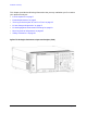
Front and Rear Panel Features Rear-Panel Features Rear-Panel Features Item Description # Name 1 NOISE SOURCE DRIVE OUT +28 V (PULSED) Provides 28 V to drive a noise source. Used on Option 219 Noise Figure personality. 2 PRESEL TUNE OUT Outputs tuning voltage for preselected harmonic mixer. 3 10 MHz OUT (SWITCHED) A switched output of the analyzer’s internal 10 MHz frequency reference signal used to lock the frequency reference of other test equipment to the analyzer.
Front and Rear Panel Features Rear-Panel Features Item # Description Name 11 KYBD Enables connection of an external PS-2 keyboard using a 6-pin mini-DIN connector. Always turn off power before plugging in keyboard. This feature not fully implemented. Currently used only for firmware upgrades. 12 Line power input The AC power connection. Also see “Power Requirements” on page 5. 13 GPIB Allows the connection of a General Purpose Interface Bus (GPIB, IEEE 488.
Front and Rear Panel Features Key Overview Key Overview The keys labeled FREQUENCY Channel, System, and Marker are all examples of front-panel keys. The front-panel keys are dark gray, light gray, green, or white in color. Front-panel keys that are white perform an immediate action rather than bringing up a menu. The only green key is the Preset key, which performs an analyzer reset (A summary of all front panel keys and their related menu keys can be found in user’s guide for your analyzer).
Front and Rear Panel Features Key Overview In other key menus, one key label will always be highlighted to show which key has been selected but the menu is immediately exited when a selection is made. For example, when you press the Orientation key (on the Print Setup menu), it will bring up its own menu of keys. The Portrait key, which is the Orientation menu default key, will be highlighted.
Front and Rear Panel Features Front and Rear Panel Symbols Front and Rear Panel Symbols This symbol is used to indicate power ON (green LED). This symbol is used to indicate power STANDBY mode (yellow LED). This symbol is used to indicate the ON position of the power button. This symbol is used to indicate the OFF position of the power button. This symbol indicates the input power required is AC. The instruction documentation symbol.
Front and Rear Panel Features Front and Rear Panel Symbols 32 Chapter 2
3 Making a Basic Measurement This chapter provides information on basic analyzer operation. For more information on making measurements, see the measurement guide for your analyzer.
Making a Basic Measurement This chapter is divided into the following sections: • “Using the Front Panel” on page 35 • “Presetting the Spectrum Analyzer” on page 36 • “Viewing a Signal” on page 37 CAUTION Ensure that the total power of all signals at the analyzer input does not exceed +30 dBm (1 watt). Basic Assumption The material in this chapter is presented with the assumption that you understand the front and rear panel layout, and display annotations of your analyzer.
Making a Basic Measurement Using the Front Panel Using the Front Panel Entering Data When setting measurement parameters, there are several ways to enter or modify the value of the active function: Knob Increments or decrements the current value. Arrow Keys Increments or decrements the current value. Numeric Keypad Enters a specific value. Then press the desired terminator (either a unit softkey, or the Enter key). Unit Softkeys Terminate a value that requires a unit-of-measurement.
Making a Basic Measurement Presetting the Spectrum Analyzer Presetting the Spectrum Analyzer Preset provides a known starting point for making measurements. The analyzer has three types of preset: Factory Preset Restores the analyzer to its factory-defined state. User Preset Restores the analyzer to a user-defined state. Mode Preset This type of preset restores the currently selected mode to a known state. For details, see the User’s/Programmer’s manual.
Making a Basic Measurement Viewing a Signal Viewing a Signal 1. Press Preset. If the softkeys Factory Preset and User Preset appear, select Factory Preset. 2. Press System, Reference, then note the 10MHz Out setting. If Off is active (underlined), press the softkey to toggle the reference on. 3. Connect the analyzer’s rear panel 10 MHz OUT (SWITCHED) to the front-panel input.
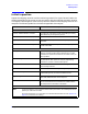
Making a Basic Measurement Viewing a Signal Figure 3-1 10 MHz Internal Reference Signal and Associated Spectrum 10 MHz Peak Setting Frequency Span 6. Set the frequency span to 50 MHz: Press SPAN, 5, 0, MHz. This displays the signal as shown in Figure 3-2.
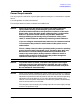
Making a Basic Measurement Viewing a Signal Figure 3-2 Span Changed to 50 MHz 10 MHz Peak Reading Frequency & Amplitude 7. Place a marker (labeled 1) on the 10 MHz peak, as shown in Figure 3-3. Press Peak Search. Note that the frequency and amplitude of the marker appear both in the active function block, and in the upper-right corner of the screen. You can use the knob, the arrow keys, or the softkeys in the Peak Search menu to move the marker. Pressing Esc removes the value from the display. 8.
Making a Basic Measurement Viewing a Signal Figure 3-3 A Marker on the 10 MHz Peak Active function block Figure 3-4 40 Marker Annotation Relationship Between Frequency and Amplitude Chapter 3
Making a Basic Measurement Viewing a Signal Improving Frequency Accuracy 10.While not all of the zeros following the decimal in the active function block are significant, the numbers after the decimal in the marker annotation (upper-right corner of screen) are significant. To increase the accuracy of the frequency reading in the marker annotation, turn on the frequency count function. a. Press Mkr Fctn. • The Marker Fctn softkeys appear. b. Press Marker Count. • The Marker Count softkeys appear. 11.
Making a Basic Measurement Viewing a Signal Figure 3-5 Increasing Marker Frequency Accuracy Frequency Count increases accuracy Figure 3-6 42 Using Marker Counter Chapter 3
4 Viewing Catalogs and Saving Files 43
Viewing Catalogs and Saving Files The analyzer stores and retrieves data similarly to the way that a personal computer (PC) does: both have internal storage and a floppy disk drive. While a PC has an internal drive, the analyzer’s internal storage is nonvolatile (flash) memory, which acts as an internal drive. As with a PC, both the internal storage and the floppy disk drive have directory and sub-directory capability; in the analyzer, directories and subdirectories are called catalogs.
Viewing Catalogs and Saving Files File Menu Functions File Menu Functions This chapter describes how to use the functions located under the front-panel File key. Data storage and retrieval are handled similarly to that of personal computers (PCs). Like PCs, these analyzers include an internal storage drive and a floppy disk drive, both of which have directory and sub-directory capability.
Viewing Catalogs and Saving Files File Menu Functions Press File, Catalog to bring up a screen display as shown in Figure 4-1. Figure 4-1. Catalog Menu NOTE Use the front-panel Step Keys or Knob and the Dir Up or Dir Select keys to move up and down within the directory information box. 1. The entry fields show the parameters for the files viewed. Entry fields that are being modified or are modifiable are indicated by highlighting (inverse video).
Viewing Catalogs and Saving Files File Menu Functions b. Type: column displays the extension of the filename, for example, .SET, .STA, .TRC. Directories are displayed as DIR and drives have nothing listed under Type:. They are only designated by the Name: column ([-A-] or [-C-]). c. Size: column displays the size of the file in bytes. d. Modified: column displays the date and time the last change occurred. 3. The softkey menu has four options: a.
Viewing Catalogs and Saving Files Saving a File Saving a File You can save files (setups, states, traces, limits, corrections, measurement results, or screens) to a floppy disk (A:\), or the internal drive (C:\). In this example you will save a trace to the internal C: drive. NOTE Trace files are not bitmap files. Files saved as Trace cannot be imported into other applications or converted.
Viewing Catalogs and Saving Files Saving a File 6. Activate trace 2 and put it into minimum hold by pressing Trace (2), Min Hold. Your analyzer display should look similar to Figure 4-4. Figure 4-3. Viewing Traces 1 and 2 7. Activate trace 3 by pressing Trace (3), Clear Write. Your analyzer display should look similar to Figure 4-5.
Viewing Catalogs and Saving Files Saving a File Figure 4-4. Viewing Traces 1, 2, and 3 Step 2. Save the file 1. To access the Save menu, press, File, Save. 2. Select the type of file you want to save. In this example you are saving a trace; press Type, Trace. NOTE Trace files are not bitmap files. Files saved as Trace cannot be imported into other applications or converted. If you require the use of other applications, for example Microsoft Word or Microsoft Excel, be sure to save your files as .
Viewing Catalogs and Saving Files Saving a File 5. Enter a filename by pressing Name. The Alpha Editor appears. For this example you will name the file, “TEST1”. (The numeric keypad is also available for the filename.) Note that the file extension is always set by the system and for this file type the extension is TRC. You must now press the Enter (hardkey) to get back to the Save menu. NOTE You need to use a filename that does not already exist in the current directory.
Viewing Catalogs and Saving Files Saving a File Loading a file 1. Reset the analyzer by pressing Preset, Factory Preset (if present). 2. To access the Load menu, press File, Load. 3. Select the type of file you want to load (setup, state, trace, limits, or corrections). In this example you are loading a trace file; press Type, Trace. NOTE Not all file types can be loaded back into the analyzer. For example, Screen files and CSV (comma separated value) files cannot be loaded.
Viewing Catalogs and Saving Files Saving a File NOTE You should notice that the trace you saved, in this example trace 3, is loaded to trace 2. If you wish to verify this condition, remove the signal input. Press Input/Output, Input Port, Amptd Ref (Off). Note that when a trace is loaded, it is placed in view mode. To see that trace 2 is in view mode, blank traces 1 and 3 by pressing View/Trace, Trace 1, Blank, Trace 3, Blank. Then press Trace 2.
Viewing Catalogs and Saving Files Saving a File Renaming a File 1. To access the Rename menu, press File, Rename. 2. Select the type of file you want to rename (setup, state, trace, limits, screens, or corrections). In this example you are renaming a trace file; press Type, Trace. 3. Select the drive and directory where your file is located. In this example, choose drive C:\START. 4. Select the file you want to rename. In this example, choose the file TEST1.TRC. 5. Press Name to open the Alpha Editor menu.
Viewing Catalogs and Saving Files Saving a File Copying a File 1. To access the Copy menu, press File, Copy. This menu function brings up 2 directory boxes as described by the From: and To: fields located directly above the boxes. Refer to Figure 4-9. Figure 4-8. Copy Menu 2. Put a formatted floppy in the A: drive. 3. Select the type of file you want to copy (setup, state, trace, limits, screens, or corrections).
Viewing Catalogs and Saving Files Saving a File NOTE Highlighting a filename in the To: directory box has no significance. The file cannot be placed inside another file. 7. Press Copy Now to execute the operation. The message: “Copying file” is displayed during the copying process. Upon completion, the status bar reads: “C:\START\RENAME.TRC file copied”. You have now copied the file RENAME from the C: drive to the A: drive. Deleting a File 1. To access the Delete menu, press File, Delete. 2.
Viewing Catalogs and Saving Files Using the Alpha Editor Using the Alpha Editor The Alpha Editor enables you to select letters to enter a name for a file or directory (File, Rename, for example). 1. Use the More keys to display the softkey that lists the character you want. Each softkey has several characters on it. 2. When you press a softkey, its characters are displayed on individual softkeys. 3. Select the one you want.
Viewing Catalogs and Saving Files Using the Alpha Editor 58 Chapter 4
5 Options and Accessories This chapter lists options and accessories available for your analyzer.
Options and Accessories Ordering Options and Accessories Ordering Options and Accessories Options and accessories help you configure the analyzer for your specific applications, and enable you to use the analyzer. Options (see page 61) Unless specified otherwise, all options are available when you order a spectrum analyzer; some options are also available as kits that you can order and install after you receive the analyzer. Order kits through your local Agilent Sales and Service Office.
Options and Accessories Options Options Option Number Name Description Manual Set on CD-ROM Only The documentation CD-ROM contains the standard documentation set as well as Adobe Acrobat Reader with Search. Additional Manual Set An additional set of the standard documentation shipped with the analyzer. See “Initial Inspection” on page 7 for information about the standard documentation set.
Options and Accessories Options Option Number Name Description 124 Y-axis Video Output Provides a 0 to 1 V signal that corresponds to the bottom and top of the display graticule, respectively. The output voltage tracks the Y-axis position of the trace data while the analyzer is sweeping. (This output is similar to the 8566B Video Out.) 202 GSM with EDGE Measurement Personality General transmitter measurement: transmit power Provides GSM (GMSK modulation) transmitter measurements: power vs.
Options and Accessories Options Option Number 226 Name Description Phase Noise Measurement Personality Provides phase noise measurements: 233 License for N5531A Measuring Receiver Software This option allows you to license your PSA to use the N5531A Measuring Receiver Software. The software networks a power meter with the PSA. The resulting system can be used as a substitute for the HP 8902A measuring receiver.
Options and Accessories Options Option Number B78 Name cdma2000 Measurement Personality Description Provides cdma2000 transmitter measurements: channel power ACPR intermodulation spectrum emission mask occupied BW code domain power modulation accuracy (composite rho) QPSK EVM power statistics CCDF Requires Option B7J hardware. B7J Digital Demod Hardware Adds 1 dB step, electronic attenuator in addition to the existing manual attenuator.
Options and Accessories Options Option Number Name Description Commercial Calibration with Test Data a Provides the factory calibration test data and the standard commercial calibration certificate at initial shipment. W30 3-Year Warranty Service Support a A total of 3 years of warranty service support. This adds a 2-year service contract to the base analyzer 1-year warranty W50 5-Year Warranty Service Support a A total of 5 years of warranty service support.
Options and Accessories Accessories Accessories A number of accessories are available from Agilent Technologies to help you configure your analyzer for your specific applications. They can be ordered through your local Agilent Sales and Service Office and are listed below. 50 Ohm/75 Ohm Minimum Loss Pad The HP/Agilent 11852B is a low VSWR minimum loss pad that allows you to make measurements on 75 Ohm devices using an analyzer with a 50 Ohm input. It is effective over a frequency range of dc to 2 GHz.
Options and Accessories Accessories GPIB Cable For use with Option A4H. The Agilent 10833 Series GPIB cables interconnect GPIB devices and are available in four different lengths (0.5 to 4 meters). GPIB cables are used to connect controllers to a spectrum analyzer. USB/GPIB Cable For use with Option A4H. The Agilent 82357A USB/GPIB interface provides a direct connection from the USB port on your laptop or desktop PC to GPIB instruments.
Options and Accessories Accessories HP/Agilent 11974 Series Preselected Millimeter Mixers 11974 Series preselected millimeter mixers are available to extend the frequency range of analyzers with Option AYZ (external mixing) up to 75 GHz. Preselection reduces mixer overload from broadband signals, reduces radiation of local oscillator harmonics back to the device under test, and reduces the level of image and multiple responses displayed. The following four models are available: Table 5-2.
6 In Case of Difficulty This chapter includes information on how to check for a problem with your Agilent Technologies spectrum analyzer, and how to return it for service. If you experience a problem or would like additional information about your analyzer, Agilent Technologies’ worldwide organization is ready to provide the support you need.
In Case of Difficulty Before calling Agilent Technologies, however (or returning an analyzer for service), perform the quick checks listed in “Check the Basics” on page 72. This check may eliminate the problem. If a problem persists, you may choose to: • Repair the analyzer yourself. See “Service Options” on page 74. • Return the analyzer to Agilent Technologies for repair. See “Returning an Analyzer for Service” on page 76, for more information. WARNING No operator serviceable parts inside.
In Case of Difficulty Types of Spectrum Analyzer Messages Types of Spectrum Analyzer Messages The analyzer can generate various messages that appear on the display during operation. For a complete list of spectrum analyzer messages, see the Instrument Messages and Functional Tests manual. The following table describes the four types of spectrum analyzer messages.
In Case of Difficulty Before Calling Agilent Technologies Before Calling Agilent Technologies Check the Basics ❏ Is there power at the receptacle? ❏ Make sure there is no disk in the front-panel disk drive. ❏ Is the analyzer turned on? Check to see if the green LED above the power switch is on. Also, listen for internal fan noise to determine if the analyzer cooling fans are running.
In Case of Difficulty Before Calling Agilent Technologies ❏ Perform an Alignment. Press System, Alignments, Align Now, All. ❏ If the previously performed alignments did not resolve the problem, press System, Alignments, Restore Align Defaults. Then press System, Alignments, Align All Now. ❏ Is the analyzer displaying an error message? If so, refer to the Instrument Messages and Functional Tests manual.
In Case of Difficulty Before Calling Agilent Technologies Read the Warranty The warranty for your analyzer is in the front of your Specifications Guide. Please read it and become familiar with its terms. If your analyzer is covered by a separate maintenance agreement, please be familiar with its terms. Service Options Agilent Technologies offers several optional maintenance plans to service your analyzer after the warranty has expired. Call your Agilent Technologies office for full details.
In Case of Difficulty Before Calling Agilent Technologies Table 6-2. Contacting Agilent Technologies Online assistance: www.agilent.
In Case of Difficulty Returning an Analyzer for Service Returning an Analyzer for Service Service Tag When you are returning an analyzer to Agilent Technologies for service, fill out and attach one of the blue service tags provided at the end of this chapter. Please be as specific as possible about the problem.
In Case of Difficulty Returning an Analyzer for Service 5. Surround the equipment with three to four inches of packing material and prevent the equipment from moving in the carton. If packing foam is not available, the best alternative is S.D.-240 Air Cap™ from Sealed Air Corporation (Hayward, California, 94545). Air Cap looks like a plastic sheet filled with 1-1/4 inch air bubbles. Use the pink-colored Air Cap to reduce static electricity.
In Case of Difficulty Returning an Analyzer for Service 78 Chapter 6
Index Numerics 10 MHz reference, turning on, 37 50 ohm/75 ohm minimum loss pad, 66 75 ohm matching transformer, 66 A AC probe, 66 Accessories, 66 accessories 50 ohm/75 ohm minimum loss pad, 66 75 ohm matching transformer, 66 AC probe, 66 broadband preamplifiers, 66 GPIB cable, 67 harmonic mixers, 67 preselected millimeter mixers, 68 RF limiters, 68 transient limiters, 68 active function, 29 address, IP, 14 Agilent Technologies, calling, 74 alignments, internal, 16 alpha editor, using, 57 amplifiers, 66 ann
Index personality options not in instrument, 14 power amplifiers, 66 preamplifiers, 66 preset factory, 36 types, 36 user, creating, 36 printer setup, 17 probes AC and DC, 66 product information, 2 R rear panel symbols, 31 rear panel features, 27 reference level, setting, 39 reference, turning on 10 MHz, 37 rename files, 54 RF limiters, 68 RPG, using, 35 RS-232 interface connector, 28 S save files, 48, 50, 52 saving bitmaps, 45, 48, 50 trace files, 45, 48, 50 screen annotation, 24 screen, information, 13 se