3Com® Switch 8800 Power Over Ethernet Installation Guide www.3Com.com Part Number: 10015270 Rev.
3Com Corporation 350 Campus Drive Marlborough, MA USA 01752-3064 Copyright © 2006, 3Com Corporation. All rights reserved. No part of this documentation may be reproduced in any form or by any means or used to make any derivative work (such as translation, transformation, or adaptation) without written permission from 3Com Corporation.
CONTENTS CONTENTS 1 INTRODUCTION Switch 8800 PoE Power Rack 5 Features 5 Architecture and Configurations 5 2 SYSTEM DESCRIPTION Overview 9 Power Supply Modules 9 PoE Power Rack 9 Power Supply Module Visual indicators System Controller 10 Distribution Panel 12 3 10 SAFETY Safety Statements 13 Warning Statements and Safety Symbols Precautions 13 4 INSTALLATION AND TESTING Introduction 15 Guidelines 15 EMI Considerations 15 Safety 15 Installation Sequence 15 Install the PoE DIMM Module 16 Technical S
CONTENTS
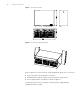
1 INTRODUCTION Switch 8800 PoE Power Rack The 3Com Switch 8800 PoE power rack is a modular, stand-alone Power over Ethernet (PoE) power source. The PoE Power Rack provides a total of 4500 Watts of DC power with 2+1 power redundancy for PoE powered devices connected to the Switch 8800 chassis.
CHAPTER 1: INTRODUCTION Figure 1 The PoE Power Rack Figure 2 The PoE Power Rack (Rear View) Refer to Figure 3 for the front view of a fully equipped PoE power rack. It consists of: ■ System controller with 2 LEDs and 3 connectors ■ Distribution panel with DC output sockets and three AC input sockets ■ Power supply modules (3 modules are shown in Figure 3) The three AC input sockets correspond to the three power supply modules (numbered from left to right).
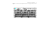
Architecture and Configurations 7 Figure 3 The PoE Power Rack Configured with Three Power Supply Modules (Front VIew)
CHAPTER 1: INTRODUCTION
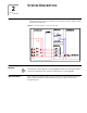
2 Overview SYSTEM DESCRIPTION Figure 4 shows the schematic diagram of the PoE Power Rack power system, showing the interconnections and signal flow through the power supply modules and internal components. Figure 4 Schematic Diagram of the PoE Power Rack Power Supply Modules DC power is supplied to the power bus by the power supply modules. The PoE Power Supply Module is interchangeable between the Switch Rack and the Switch 8800 PoE Power Rack. NO other components are interchangeable.
CHAPTER 2: SYSTEM DESCRIPTION Power Supply Module Visual indicators The front panel of the power supply module has three LEDs (Figure 5). Their descriptions, colors, and functions are shown in Table 2.
System Controller 11 ■ Monitor system operation status - An AC sensor card inside the PoE Power Rack samples the AC input voltage. The sampled signal is sent to the controller for processing. If the AC input voltage is lower than the pre-set alarm level, the controller reports an AC input under-voltage alarm. Likewise, if the input voltage is higher than the pre-set alarm level, the controller reports an AC input over-voltage alarm. The DC output voltage is also sampled and sent to the controller.
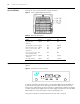
CHAPTER 2: SYSTEM DESCRIPTION Distribution Panel The distribution panel consists of DC output sockets and three AC input sockets. Refer to Figure 7. Figure 7 Distribution Panel The three EN60320 C20 AC input sockets on the front panel of the device are rated at 20A@250VAC. Each socket supplies power to one power supply module. There is an AC power ON/OFF switch beside each AC input socket for individual power switching.
SAFETY 3 Safety Statements Please read and follow all safety instructions and warnings before servicing the PoE Power Rack. Refer to the individual module product manuals for additional safety statements specific to the modules. ■ The device must be in a restricted access area (dedicated equipment rooms, equipment closets, etc.) where the applicable requirements of the device are met.
CHAPTER 3: SAFETY electrical equipment and who understand the hazards that can arise when working on this equipment. ■ The PoE Power Rack can be powered by multiple AC inputs, ensure that the appropriate circuit protection device for each AC input being serviced is disconnected before changing or servicing a Power Supply Module. If servicing the PoE Power Rack, all the AC power cords must be removed from the equipment. ■ High leakage currents may be possible on this type of equipment.
4 INSTALLATION AND TESTING Introduction This section outlines the sequence for installing the PoE Power Rack, including plug-in modules. Test procedures for verifying the integrity of the installation are also included. Guidelines The device must be installed to allow sufficient front and rear access. All cables must be routed through insulated conduit openings. All service operations can be completed on the front of the power rack.
CHAPTER 4: INSTALLATION AND TESTING Install the PoE DIMM Module If you are installing the optional PoE DIMM module, use the following instructions. Technical Specifications The technical specifications of PoE DIMM (Dual In-line Memory Module) are listed in Table 5. Table 5 Technical specifications of PoE DIMM module Model Number of ports Type Disconnect Detection PD67024MUAC 24 Master AC Powered devices compliant with IEEE 802.
Installation Sequence 17 3 The following items are included in the unit packaging: PoE Power Rack, power supply module, dummy faceplates and cables. Remove all this material and place aside. Mounting screws are NOT supplied with the PoE Power Rack. Mounting screws may be obtained from the equipment rack/cabinet supplier. 4 It is your option to remove power supply module and dummy faceplates or before installation. Removing them makes the next step easier. Refer to Figure 8.
CHAPTER 4: INSTALLATION AND TESTING Install Power Supply Modules Power Supply Modules are installed by sliding into the power rack, pushing until the power supply module is fully inserted, and closing the handle on the power supply module. Refer to Figure 10. 1 Verify that the AC power switches on the AC distribution panel are in the "OFF" position . 2 Insert the power supply module into the PoE Power Rack and slide it toward the backplane until it contacts the backplane connectors.
Installation Sequence Connecting to AC utility/ AC grounding 19 AC power input is accessed from the front of the unit. AC power cord connection is made using power cords with IEC 60320 C-19 connector plugs. The AC power plugs are labeled Input 1, Input 2, and Input 3, which correspond to the power supply modules numbered from left to right. Refer to Figure 12. To connect AC power: 1 Turn the AC branch circuit breakers to the "OFF" position. 2 Ensure that the AC input switches are in the "OFF" position.
CHAPTER 4: INSTALLATION AND TESTING
5 Maintenance and Troubleshooting ENGINEERING, MAINTENANCE AND TROUBLESHOOTING This section provides field maintenance information and troubleshooting procedures for the PoE Power Rack and power supply modules. Review the safety information in section 3 of this manual before performing maintenance procedures All procedures described in this section must be performed by qualified maintenance personnel only. The power supply modules are not field serviceable and must be replaced in the event of a failure.
CHAPTER 5: ENGINEERING, MAINTENANCE AND TROUBLESHOOTING Table 6 Troubleshooting Guide Controller alarm status Power supply module display Possible problems Possible solution ALM or None -- Controller failure Replace the controller