Installation Guide ProCurve Switch xl Modules PoE Power over Ethernet Devices www.procurve.
ProCurve Switch xl Modules Installation Guide
© Copyright 2001, 2005 - 2007 Hewlett-Packard Development Company, L.P. Disclaimer Publication Number The information contained herein is subject to change without notice.The only warranties for HP products and services are set forth in the express warranty statements accompanying such products and services. Nothing herein should be construed as constituting an additional warranty. HP shall not be liable for technical or editorial errors or omissions contained herein.
Contents Descriptions . . . . . . . . . . . . . . . . . . . . . . . . . . . . . . . . . . . . . . . . . . . . . . . . . . . . . 1 Features . . . . . . . . . . . . . . . . . . . . . . . . . . . . . . . . . . . . . . . . . . . . . . . . . . . . . . . . . 4 Module Features - J8162A, J9001A, J9003A . . . . . . . . . . . . . . . . . . . . . . . . 6 Battery Installation Required . . . . . . . . . . . . . . . . . . . . . . . . . . . . . . . . . 7 Module Features and Supported Standards . . . . . . . . . . . . . .
Troubleshooting . . . . . . . . . . . . . . . . . . . . . . . . . . . . . . . . . . . . . . . . . . . . . . . . . 31 PoE LED Behavior . . . . . . . . . . . . . . . . . . . . . . . . . . . . . . . . . . . . . . . . . . . 31 LED Error Indicators: . . . . . . . . . . . . . . . . . . . . . . . . . . . . . . . . . . . . . . 32 Diagnostic Tips: . . . . . . . . . . . . . . . . . . . . . . . . . . . . . . . . . . . . . . . . . . . . . . 32 Customer Support Services . . . . . . . . . . . . . . . . . . . . . . . . .
ProCurve Switch xl Modules Descriptions ProCurve Switch xl Modules For the ProCurve Series 5300xl Switches Descriptions. The ProCurve Switch xl Modules are components that you can add to a ProCurve xl switch to provide a variety of network connectivity options.
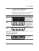
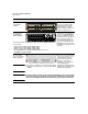
ProCurve Switch xl Modules Descriptions Module ProCurve Switch PoE xl Module (J8161A) 2 PoE Link EPS Status LED Mode Std Description PoE-Ready 10/100-TX Ports (1-24) all ports are HP Auto-MDIX PoE 1 Mode 2 3 4 5 7 8 9 10 11 6 13 14 15 16 17 Link 18 Mode 20 21 22 23 24 PoE hp procurve PoE xl module J8161A xl 12 19 module 24 10/100-TX ports and when connected to a ProCurve 600 Redundant and External Power Supply (J8168A), can provide Power over Ethernet (PoE) power to 802
ProCurve Switch xl Modules Descriptions Module ProCurve Wireless Edge Services xl Module (J9001A)5 Description There are no ports on the J9001A. The module enables the Switch 5300xl to operate with ProCurve Radio Ports as a centrallyadministered Wireless LAN system. Note Due to power consumption, no more than two of the following modules may be installed in a chassis: J8162A, J9001A, For configuration information see your ProCurve Series 5300xl or J9003A.
ProCurve Switch xl Modules Features Module ProCurve Switch xl 1-Port 10-GbE Module (J8988A)6 Description 1 port for installing any of the supported ProCurve 10 Gig X2 transceivers.
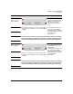
ProCurve Switch xl Modules Features Link and Mode LEDs port cover Figure 2. Example ProCurve Switch 1-port 10 Gig-X2 xl Module LED Mode Select Button PoE Link EPS Status EPS Input LED Mode Std PoE-Ready 10/100-TX Ports (1-24) all ports are HP Auto-MDIX PoE 1 Mode 2 3 4 5 7 8 9 10 11 6 13 14 15 16 17 20 21 22 23 Link 18 Mode PoE hp procurve PoE xl module J8161A xl 12 19 Link and Mode LEDs (one pair per port) 24 module Network ports Figure 3.
ProCurve Switch xl Modules Features Module Features - J8162A, J9001A, J9003A ■ Shutdown Module—This is a recessed push button switch that when pressed and held for more than 2 seconds, initiates an orderly shutdown. During the shutdown process the Module Ready LED blinks. When the shutdown is complete enough for a safe module removal, the Module Ready LED turns off. It is highly recommended to shutdown the module before resetting or removing the module.
ProCurve Switch xl Modules Features • Downlink Ports—This LED is associated with the Locate Ports button and comes on when the button is pressed once. • Uplink Network Ports—This LED is associated with the Locate Ports button and comes on when the button is pressed for the second time. ■ Module Ready LED—This LED comes on after the module completes the boot up and self test processes and indicates the module is up and running.
ProCurve Switch xl Modules Features C R203 2 Insert the battery with the lettering and the plus “+” sign facing up. Battery LL 3 VO E LT LITHIUM C Battery Slot Figure 5. Installing a module battery AT T E N T I O N ll y a danger d'explosion s'il y a remplacement incorrect de la batterie. Remplacer uniquement avec une batterie du même type ou d'un type équivalent recommandé par le constructeur. Mettre au rebut les batteries usagées conformément aux instructions du fabricant.
ProCurve Switch xl Modules Features ■ “hot swap X2 transceiver” operation—you can add, replace, or change the type of any of the X2 transceivers that you use in the 10-GbE xl Module, without having to first remove the module, and without having to shut down the switch (you must remove the network cable before hot-swapping a transceiver) ■ the ports on the 10/100-TX and PoE Modules have the HP Auto-MDIX feature, and the ports on the 100/1000-T xl Module have the IEEE 802.3ab Auto MDI/MDI-X feature.
ProCurve Switch xl Modules Installing the Modules Installing the Modules Overview Before installing any module, ensure you have loaded the most current software for that module onto your switch, see page 4 for module software codes. You can install any of the modules into any of the ProCurve xl Switches that have a compatible module slot.
ProCurve Switch xl Modules Installing the Modules Installing the Module in an Unused Slot Installation Precautions: ■ Static electricity can severely damage the electronic components on the modules. When handling and installing the modules in your switch, follow these procedures to avoid damage from static electricity: • Handle the module by its bulkhead or edges and avoid touching the components and the circuitry on the board.
ProCurve Switch xl Modules Installing the Modules 1. Insert module into the guides and slide it in until it is fully inserted. “Low-force” connector. High insertion force is not needed and should not be used. For best results, push simultaneously near both screws. Figure 6. Installing a Module The module is fully inserted when the module bulkhead is contacting, or very close to contacting the face of the switch. 2.
ProCurve Switch xl Modules Installing the Modules Installing or Removing the mini-GBICs You can install or remove a mini-GBIC from the mini-GBIC xl Module without having to power off the switch. Use only ProCurve mini-GBICs. WA R N I N G The ProCurve mini-GBICs are Class 1 laser devices. Avoid direct eye exposure to the beam coming from the transmit port. Caution Use only supported genuine ProCurve mini-GBICs with your switch.
ProCurve Switch xl Modules Installing the Modules Install or Remove a Transceiver Note Hot swapping transceivers is supported. You can install or remove a transceiver with the switch powered on, a reset will not occur. a. Remove the 10-GbE port cover. b. Slide the transceiver in until it stops. Figure 9. Installing an X2 transceiver c. Push firmly until the gasket seats against the bulkhead. The transceiver should “click” into place. Figure 10.
ProCurve Switch xl Modules Installing the Modules Connecting a ProCurve External Power Supply Power over Ethernet technology allows IP telephones, wireless LAN Access Points and other appliances to receive power as well as data over existing LAN cabling, without needing to modify the existing Ethernet infrastructure. For more information on PoE, refer to the ProCurve PoE Planning and Implementation Guide.
ProCurve Switch xl Modules Installing the Modules 4. Secure the CRB to the module bulkhead. Figure 12. Securing the CRB 5. Install (or re-install) the RJ45 connectors in ports 6 and 13. The opposite procedure is used when disconnecting the EPS cable connector. Connecting or disconnecting RJ-45 connectors To insert or remove an RJ-45 connector in port 6 or 13, depress the RJ-45 connector clip in order to clear the EPS cable retention bracket. Figure 13.
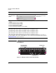
ProCurve Switch xl Modules Installing the Modules ProCurve Switch PoE xl Module Configurations For the ProCurve Switch PoE xl Module to function it must be installed in any slot of a ProCurve Switch 5300xl. The module will receive it’s operational power from the switch and it’s PoE power from the 600 RPS/EPS or the 610 EPS. The following examples show some possible configurations.
ProCurve Switch xl Modules Installing the Modules Std Link LED Mode PoE PoE 1 Mode 2 3 4 7 8 9 10 PoE-Ready 10/100-TX Ports (1-24) all ports are HP Auto-MDIX EPS Status 5 6 13 14 15 16 17 20 21 22 23 Link Std Link 18 Mode xl J8161A Std Std Link 1 Mode 2 LED Mode 3 PoE PoE 4 PoE-Ready 10/100-TX Ports (1-24) all ports are HP Auto-MDIX EPS Status 5 6 13 14 15 16 17 Std Link Link 18 Mode Mode LED Mode PoE PoE 2 3 4 8 9 10 PoE-Ready 10/100-TX Por
ProCurve Switch xl Modules Installing the Modules In the default switch configuration all PoE ports have a Low priority. If the switch has less than 15.4 W of PoE power available, the switch transfers power from lower-priority ports to higher-priority ports. Within each priority class, a lower numbered port is supplied power before a higher numbered port.
ProCurve Switch xl Modules Installing the Modules Status LEDs There are two status LEDs: ■ PoE - lights when PoE power is being supplied to one or more PDs. It goes out when there are no valid loads attached to any of the ports. It will blink to indicate an error on any of the ports or when any port is denied PoE power. ■ EPS - lights when the module is connected to a 600 RPS/EPS or a 610 EPS. It goes out when the 600 RPS/EPS or 610 EPS is disconnected from the module.
ProCurve Switch xl Modules Installing the Modules Verifying the Module is Installed Correctly Observe the Module Status LED for the slot in which the module is being installed, and the Self Test and Fault LEDs on the switch to verify the module is installed properly.
ProCurve Switch xl Modules Installing the Modules Connecting the Network Cables Connect the appropriate network cables to the module's ports as shown in the table below. For more information on the cable specifications, see “Cables” on page 37.
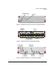
ProCurve Switch xl Modules Installing the Modules Module mini-GBIC and the 10/100/1000-T xl Modules Link hp procurve 1 1 2 3 3 2 4 4 mini-GBIC xl module J4878A Maximum Length Gigabit-SX operation: multimode fiber-optic cables fitted with LC connectors 220 meters to 550 meters, depending on the cable used. See “Fiber-Optic Cables” on page 38 for more information. Gigabit-LX operation: single-mode fiberoptic cables fitted with LC connectors.
ProCurve Switch xl Modules Installing the Modules Module Cable Type 100-FX MTRJ xl Module Link|Mode 1 2 3 4 5 6 7 8 9 10 11 12 100Base-FX MTRJ Ports 1 2 3 4 5 6 7 8 9 10 11 12 hp procurve xl 100-FX MTRJ xl module module J4852A multimode fiber-optic cables fitted with MT-RJ connectors. See “Fiber-Optic Cables” on page 38 for more information.
ProCurve Switch xl Modules Installing the Modules Connecting the 10-GbE Network cables Connecting a fiber cable. 1. Remove the dust covers from the cable connectors and the port. 2. Aligning the notches on the cable connectors with the slots of the port, press the cable connector into the port until it snaps into place. If the Link LED does not go on when the network cable is connected to the port, see the Troubleshooting section on page 31. 2 Figure 17.
ProCurve Switch xl Modules Installing the Modules Note Automatic Cable Sensing on Twisted-Pair Ports: When the ports for the 10/100-TX, 100/1000-T, 10/100/1000-T, and the PoE xl Modules are in their default configuration, Auto, they automatically negotiate whether the ports operate as MDI or MDI-X, depending on the cable type and the connected device’s operation. As a result, you can use either straightthrough or crossover twisted-pair cable for all network connections to these modules.
ProCurve Switch xl Modules Installing the Modules ■ The Link LED will be lit for each port that is connected properly to an active network device. If the Link LED does not go on when an active network cable is connected to the port, there may be something wrong with the cable, the cable connectors, or the device at the other end of the cable. See the troubleshooting information on page 31.
ProCurve Switch xl Modules Installing the Modules • Gigabit-SX, Gigabit-LX, and Gigabit-LH ports in mini-GBIC xl Module: Auto — The port always operates at 1000 Mbps and full duplex. The setting is Auto for best link establishment with other devices. • 100-FX MTRJ xl Modules: 100FDX — The port operates at 100 Mbps and full-duplex. • 10/100/1000-T xl Modules: Auto — The port auto negotiates speed (10, 100 or 1000 Mbps), communication mode (half or full duplex), and MDI or MDI-X port operation.
ProCurve Switch xl Modules Replacing or Removing a Module Replacing or Removing a Module Follow these procedures to replace one module with another, or to remove a module without replacing it: 1. Remove any network cables from the ports on the module. (If this is a PoE xl Module, also remove the PoE cable.) 2. On the module you want to remove from the switch, unscrew the retaining screws enough to disconnect them from the threaded holes in the switch.
ProCurve Switch xl Modules Resetting the Switch Resetting the Switch Reasons for Resetting the Switch Generally, you only need to reset the switch when it needs to recognize a change in its hardware or software (console) configuration.
ProCurve Switch xl Modules Troubleshooting Troubleshooting One of the primary tools for troubleshooting the switch modules are the LEDs on the front of the switch and on the modules. Refer to “LED Behavior” on page 21 for a description of the normal LED behavior. Also, refer to the switch Installation and Getting Started Guide for more detailed troubleshooting information for the switch. PoE LED Behavior EPS Condition EPS Status EPS Fault LED EPS Device Conn.
ProCurve Switch xl Modules Troubleshooting On - When power is being supplied to the ports Off - When power is not requested Slow Blink - When power is requested, but not supplied Switch and Module LED Error Indicators: Fault Self Test † Blinking † † Blinking † Module Status Port Link Diagnostic Tips † Never On ➊ † Blinking Blinking Blinking Blinking On briefly, then Off ➋ Off Off Blinking† Off ➌ Blinking† Blinking† Blinking† Blinking† ➍ Off Off Off Fast Blinking†† ➎ Off
ProCurve Switch xl Modules Troubleshooting Tip Number ➋ Problem Solution The module installed in the slot that corresponds to the letter that is blinking has experienced a self test or initialization fault. The modules are all tested whenever the switch is powered on, or reset (through the Reset button on the switch, or the Reboot or Reset options in the console or web browser interface), and when they are hot swapped (installed when the switch is powered on).
ProCurve Switch xl Modules Troubleshooting Tip Number ➍ Problem Solution The network port for which the Link LED is blinking has experienced a self test or initialization failure. During the module self test (described in item 1 above), each network port is also tested. If the port self test fails, the individual port is not usable, but the rest of the ports on the module, which have passed their self test, will continue to operate normally.
ProCurve Switch xl Modules Troubleshooting Tip Number ➏ Problem The network connection is not working properly. Solution Try the following procedures: • For the indicated port, verify both ends of the cabling, at the switch and the connected device, are securely connected. • Verify the connected device and switch are both powered on and operating correctly. • Verify you have used the correct cable type for the connection. See “Cables” on page 37 for the correct cable specifications.
ProCurve Switch xl Modules Customer Support Services Customer Support Services If you are having any trouble with your module or switch, Hewlett-Packard offers support 24 hours a day, seven days a week through the use of a number of automated electronic services. See the Customer Support/Warranty booklet that came with your switch for information on how to use these services to get technical support. The ProCurve Networking products Web site, www.procurve.com also provides up-to-date support information.
ProCurve Switch xl Modules Specifications Cables Twisted-Pair Cables Port Type Cable Specifications Maximum Length 10 Mbps Operation Category 3, 4, or 5 100-ohm balanced unshielded twisted-pair (UTP) or shielded twisted-pair (STP) cable, complying with IEEE 802.3 10Base-T specifications, fitted with RJ-45 connectors 100 meters 100 Mbps Operation Category 5 100-ohm balanced UTP or STP cable, complying with IEEE 802.
ProCurve Switch xl Modules Specifications Fiber-Optic Cables Port Type Cable Specifications Connector Type Maximum Length 100Base-FX 62.5/125 μm or 50/125 μm (core/cladding) diameter, graded-index, low metal content, multimode fiber-optic cables, complying with the ITU-T G.651 and ISO/IEC 793-2 Type A1b or A1a respectively. MT-RJ Gigabit-SX 62.5/125 μm or 50/125 μm (core/cladding) diameter, graded-index, low metal content, multimode fiber-optic cables, complying with the ITU-T G.
ProCurve Switch xl Modules Specifications Fiber-Optic Cables Port Type Cable Specifications Connector Type Supported Length 10-GbE SR Multimode fiber-optic cable designed for Gigabit Ethernet: 62.5/125 μm (core/cladding) diameter or 50/125 μm, low metal content, complying with the ITU-T G.651 and ISO/IEC 793-2 Type A1b or A1a respectively. SC 10-GbE LR 9/125 μm (core/cladding) diameter, low metal content, single mode fiber-optic cables, complying with the ITU-T G.
ProCurve Switch xl Modules Specifications Optical Power Specifications ProCurve 10-GbE X2-SC SR optic Transmitter Optical Characteristics: Parameter Center Wavelength Minimum Typical Maximum 840nm 850nm 860nm Spectral Width Notes 0.45 nm Average Launch Power -7.3 dBm Extinction Ratio 3 dB -1.0 dBm RIN (Relative Intensity Noise) -128 dB/Hz Receiver Optical Characteristics: Parameter Center Wavelength Average Receive Power Minimum Typical Maximum 840nm 850nm 860nm -9.9 dBm Notes -1.
ProCurve Switch xl Modules Specifications Receiver Optical Characteristics: Parameter Center Wavelength Average Receive Power Minimum Typical Maximum 1260 nm 1310 nm 1355 nm - 14.4 dBm Notes 0.5 dBm Receiver Sensitivity -12.6 dBm ProCurve 10-GbE X2-SC ER optic Transmitter Optical Characteristics: Parameter Minimum Typical Maximum Center Wavelength 1530 nm 1550 nm 1565 nm Average Launch Power -4.7 dBm Extinction Ratio 3.0 dB Notes 4.
ProCurve Switch xl Modules Specifications ProCurve 10-GbE X2-CX4 Transceiver Copper Transceiver Characteristics: Parameter Minimum Typical Maximum OMC Supply Voltage 3.3V* 3.13 VDC 3.3 VDC 4.37 VDC 196 mA 216 mA OMC Supply Current 3.
ProCurve Switch xl Modules Mode Conditioning Patch Cord for Gigabit-LX Mode Conditioning Patch Cord for Gigabit-LX The following information applies to installations in which multimode fiberoptic cables are connected to a Gigabit-LX port. Unlike Gigabit-SX, which connects to only multimode fiber-optic cabling, Gigabit-LX can use either single-mode or multimode cable.
ProCurve Switch xl Modules Mode Conditioning Patch Cord for Gigabit-LX Installing the Patch Cord As shown in the illustration below, connect the patch cord to the Gigabit-LX mini-GBIC with the section of single-mode fiber plugged in to the Tx (transmit) port. Then, connect the other end of the patch cord to your network cabling patch panel, or directly to the network multimode fiber.
ProCurve Switch xl Modules EMC Regulatory Statements EMC Regulatory Statements U.S.A. FCC Class A This equipment has been tested and found to comply with the limits for a Class A digital device, pursuant to Part 15 of the FCC Rules. These limits are designed to provide reasonable protection against interference when the equipment is operated in a commercial environment.
ProCurve Switch xl Modules EMC Regulatory Statements Korea Taiwan European Community Declaration of Conformity These products are designed for operation with the ProCurve switches that have xl module slots. Please see the Declarations of Conformity included in the Installation Guides for those products.
ProCurve Switch xl Modules Waste Electrical and Electronic Equipment (WEEE) Statements Waste Electrical and Electronic Equipment (WEEE) Statements Disposal of Waste Equipment by Users in Private Household in the European Union This symbol on the product or on its packaging indicates that this product must not be disposed of with your other household waste.
ProCurve Switch xl Modules Waste Electrical and Electronic Equipment (WEEE) Statements Élimination des appareils mis au rebut par les ménages dans l'Union européenne Le symbole apposé sur ce produit ou sur son emballage indique que ce produit ne doit pas être jeté avec les déchets ménagers ordinaires. Il est de votre responsabilité de mettre au rebut vos appareils en les déposant dans les centres de collecte publique désignés pour le recyclage des équipements électriques et électroniques.
ProCurve Switch xl Modules Waste Electrical and Electronic Equipment (WEEE) Statements Nolietotu iekārtu iznīcināšanas noteikumi lietotājiem Eiropas Savienības privātajās mājsaimniecībās Šāds simbols uz izstrādājuma vai uz tā iesaiņojuma norāda, ka šo izstrādājumu nedrīkst izmest kopā ar citiem sadzīves atkritumiem. Jūs atbildat par to, lai nolietotās iekārtas tiktu nodotas speciāli iekārtotos punktos, kas paredzēti izmantoto elektrisko un elektronisko iekārtu savākšanai otrreizējai pārstrādei.
ProCurve Switch xl Modules Waste Electrical and Electronic Equipment (WEEE) Statements Likvidácia vyradených zariadení v domácnostiach v Európskej únii Symbol na výrobku alebo jeho balení označuje, že daný výrobok sa nesmie likvidovať s domovým odpadom. Povinnosťou spotrebiteľa je odovzdať vyradené zariadenie v zbernom mieste, ktoré je určené na recykláciu vyradených elektrických a elektronických zariadení.
© Copyright 2001, 2005 - 2007 Hewlett-Packard Development Company, L.P.