HP 3PAR StoreServ 7450 Storage Service Guide Abstract This guide provides information about maintenance and upgrading HP 3PAR StoreServ 7450 Storage system hardware components for authorized technicians.
© Copyright 2014 Hewlett-Packard Development Company, L.P. The information contained herein is subject to change without notice. The only warranties for HP products and services are set forth in the express warranty statements accompanying such products and services. Nothing herein should be construed as constituting an additional warranty. HP shall not be liable for technical or editorial errors or omissions contained herein. Acknowledgments Microsoft®, Windows®, are U.S.
Contents 1 Understanding LED Indicator Status...............................................................5 Enclosure LEDs.........................................................................................................................5 Bezels LEDs.........................................................................................................................5 Disk Drive LEDs....................................................................................................................
Documentation feedback...........................................................................43 A Installing Storage Software Manually..........................................................44 Connecting to the Laptop.........................................................................................................44 Connecting the Laptop to the Controller Node.......................................................................44 Connecting the Laptop to the HP 3PAR Service Processor.......
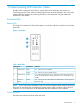
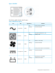
1 Understanding LED Indicator Status Storage system components have LEDs to indicate status of the hardware and whether it is functioning properly. These indicators help diagnose basic hardware problems. You can quickly identify hardware problems by examining the LEDs on all components using the tables and illustrations in this chapter. Enclosure LEDs Bezels LEDs The bezels are located at the front of the system on each side of the drive enclosure and include three LEDs.
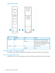
Figure 2 Disk Drive LEDs Table 2 Disk drive LEDs LED Appearance Status Indicates 1 - Fault Amber On Disk failed and is ready to be replaced. Flashing The locatecage command has been issued. Fault LEDs for failed disk drives do not flash. The I/O module Fault LEDs at the rear of the enclosure also blink. On Normal operation Flashing Activity 2 - Activity Green Storage System Component LEDs The storage system includes the following components in the enclosure at the rear of the system.
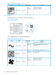
Figure 3 PCM LEDs The following table describes the LED states.
Table 3 PCM LED Descriptions (continued) Icon LED Battery Good Appearance Indicates On Present and charged Flashing Charging or disarmed Green Drive PCM LEDs The following figure shows the drive enclosure PCM LEDs. Figure 4 Drive PCM LEDs The next table describes the drive PCM LED states.
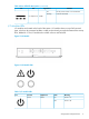
Table 4 Drive PCM LED Descriptions (continued) Icon LED DC Output Fail Appearance Indicates On No AC power or fault or out of tolerance Flashing Firmware download Amber I/O Modules LEDs I/O modules are located on the back of the system. I/O modules have two mini-SAS universal ports, which can be connected to HBAs or other ports and each port includes External Port Activity LEDs, labeled 0–3. The I/O module also includes a Power and Fault LED.
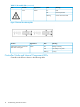
Table 5 I/O module LEDs (continued) Icon Function Appearance State Meaning Fault Amber On Fault Off Normal operation Flashing Locate command issued Figure 7 External Port Activity LEDs Function Appearance State Meaning External Port Activity; 4 LEDs for Data Ports 0 through 3 Green On Ready, no activity Off Not ready or no power Flashing Activity Controller Node and Internal Component LEDs Controller node LEDs are shown in the following table.
Figure 8 Controller Node LEDs NOTE: Issue the locatenode command to flash the UID LED blue.
Table 6 Controller Node LEDs (continued) Unit ID Fault Blue Amber On OK to remove Off Not OK to remove Flashing Locate command issued On Fault Off No fault Flashing Node in cluster and there is a fault Ethernet LEDs The controller node has two built-in Ethernet ports and each includes two LEDs: • MGMT — Eth0 port provides connection to the public network • RC-1 — designated port for Remote Copy functionality Figure 10 Ethernet LEDs Table 7 Ethernet LEDs Left LED Right LED Link Up Spee
Figure 11 FC Port LEDs Table 8 FC Port LEDs All ports No light Off Wake up failure (dead device) or power is not applied FC-1 Amber Off Not connected 3 fast blinks Connected at 4GB/sec. 4 fast blinks Connected at 8GB/sec.
Converged Network Adapter (CNA) LEDs Figure 13 CNA LEDs Table 10 CNA LEDs Upper Lower Link ACT (Activity) Off Link down On Link up Off No activity On Activity Green Green Node FC and CNA Port Numbering Port position is displayed as Node:Slot:Port (N:S:P) in the Management Console.
Table 12 FC Adapter Ports Port Slot:Port 1 2:1 2 2:2 3 2:3 4 2:4 Figure 16 CNA Ports Table 13 CNA Ports Port Slot:Port 1 2:1 2 2:2 SAS Port LEDs The controller node has two SAS ports and each includes four LEDs, numbered 0–3: Figure 17 SAS port LEDs Controller Node and Internal Component LEDs 15
Table 14 SAS port LEDs Appearance Indicates Green Off No activity on port. This LED does not indicate a Ready state with a solid On as the I/O Module External Port Activity LEDs do. Flashing Activity on port Interconnect Port LEDs The controller node has two interconnect ports and each includes two LEDs. NOTE: Incorrectly configured interconnect cables illuminate amber port LEDs.
Figure 20 Front Panel LEDs Table 16 Front panel LEDs Item LED Appearance Description 1 UID LED/button Blue Active Flashing Blue System is being managed remotely Off Deactivated Green System is on Flashing Green Waiting for power Amber System is on standby, power still on Off Power cord is not attached or power supplied has failed Green System is on and system health is normal Flashing Amber System health is degraded Flashing Red System health is critical Off System power is off
Table 17 Rear panel LEDs Item LED Appearance Description 1 NIC link Green Link Off No link Green or Flashing Green Activity Off No activity Blue Active Flashing Blue System is being managed remotely Off Deactivated Green Normal Off Off = one or more of the following conditions: 2 3 4 NIC status UID LED/button Power supply • Power is unavailable • Power supply has failed • Power supply is in standby mode • Power supply error 18 Understanding LED Indicator Status
2 Servicing the Storage System Use this chapter to perform removal and replacement procedures on the HP 3PAR StoreServ 7450 Storage systems. CAUTION: Before servicing any component in the storage system, prepare an Electrostatic Discharge-safe (ESD) work surface by placing an antistatic mat on the floor or table near the storage system. Attach the ground lead of the mat to an unpainted surface of the rack. Always use a wrist-grounding strap provided with the storage system.
The materials shipped with a replacement CSR part specify whether a defective part must be returned to HP. When required, you must ship the defective part to HP within a defined period of time, normally five business days. The defective part must be returned with the associated documentation in the provided shipping material. Failure to return the defective part could result in HP billing you for the replacement.
Figure 23 Product label with HP Spare part number Swappable Components Colored touch points on a storage system component (such as a lever or latch) identify whether the system should be powered on or off during a part replacement: • Hot-swappable – Parts are identified by red-colored touch points. The system can remain powered on and active during replacement. NOTE: Disk drives are hot-swappable, even though they are yellow and do not have red touch points.
1. Follow the link to alert actions under Recommended Actions (see Figure 24 (page 22)). Figure 24 Verify Drive Failure Alert 2. 3. 4. 5. 6. At the HP Storage Systems Guided Troubleshooting web site, follow the link for your product. At the bottom of the HP 3PAR product page, click the link for HP 3PAR Alert Messages. At the bottom of the Alert Messages page, choose the correct message code series based on the first four characters of the alert message code.
2. 3. 4. 5. 6. Select Halt a StoreServ cluster/node. Follow the prompts to shutdown an HP 3PAR StoreServ cluster. Do not shut down individual Nodes. Turn off power to the node PCMs. Turn off power to the drive enclosure PCMs. Turn off all PDUs in the rack. Using SPMAINT 1. 2. 3. 4. 5. 6. Select option 4 (StoreServ Product Maintenance). Select Halt a StoreServ cluster/node. Follow the prompts to shutdown an HP 3PAR StoreServ cluster. Do not shut down individual Nodes. Turn off power to the node PCMs.
3. Ensure the PDUs are in a fully lowered position before accessing. Figure 25 Disengaging the PDU Pivot Brackets Replacing an Interconnect Link Cable Before replacing an Interconnect Link cable, verify with the system administrator before powering off the system. 1. Shutdown all the controller nodes in the system. 2. Turn off power to the controller node PCMs. 3. Turn off power to the drive enclosure PCMs. 4. Turn off power to all PDUs in the rack. 5. Replace the damaged cable.
NOTE: SSDs have a limited number of writes that can occur before reaching the SSD's write endurance limit. This limit is generally high enough so wear out will not occur during the expected service life of an HP 3PAR StoreServ under the great majority of configurations, input/output patterns, and workloads. HP 3PAR StoreServ tracks all writes to SSDs and can report the percent of the total write endurance limit that has been used.
Figure 27 Filtered Table The Alert tab displays a filtered Alert table showing only the critical alerts associated with disk drives, where the alert details are displayed (see Figure 28 (page 26)). NOTE: The lower pane lists the alerts in a tabular fashion (you can see the highlighted alert in Figure 28 (page 26)). Highlighted alerts display their details in the pane above the list. Figure 28 Alert Details 3. Double click the relevant alert to display the alert details. Disk Drive (Magazine) Location 1.
Figure 30 Tool Bar Locate Icon 4. In the Locate Cage dialog box, enter an appropriate time to allow service personnel to view the LED status of the Drive Enclosure (Cage). See Figure 31 (page 27). NOTE: If necessary, use the Stop Locate icon to halt LED flashing. Figure 31 Locate Cage Dialog Box An icon with a flashing LED will be shown next to the cage, which flashes all drives in this cage except the failed drive. Removing a 2.5 inch Disk 1. 2. 3.
4. Remove the replacement disk drive from its packaging. To reinstall a new disk drive, see “Installing a Disk Drive” (page 29). Figure 32 7200 and 7400 Two Node System (HP M6710 Drive Enclosure) Removing a 3.5 inch Disk To remove a 3.5 inch disk drive: 1. Pinch the latch in the handle towards the hinge to release the handle. 2. Gently pull the disk drive out approximately one inch and wait 30 seconds. 3. Slide the disk drive out of the enclosure and set aside. 4.
Installing a Disk Drive CAUTION: Blank disk drive carriers are provided and must be used if all slots in the enclosure are not filled with disk drives. CAUTION: NOTE: type. To avoid potential damage to equipment and loss of data, handle disk drives carefully. All drives in a vertical column of an LFF drive enclosure must be the same speed and Installing a 2.5 inch disk drive (SFF) 1. 2. 3. Press the handle latch to open the handle.
3. Push firmly until the handle fully engages and clicks. Figure 35 Installing a 3.5 inch disk drive Verifying Disk Drives 1. 2. Verify the disk drive has been successfully replaced. Redisplay the physical disks to monitor. Open the system in the Systems tab and select Physical Disks. NOTE: Users can select the column header State to resort. NOTE: Until data has been restored, the original disk drive will display as Failed and the replacement disk drive will display as Degraded. 3.
NOTE: Do not order a replacement node until the ASP has verified the failure, including a procedure to reset the node. CAUTION: Alloy gray-colored latches on components like the node means that the component is warm-swappable. HP recommends that the node be shutdown (with the power remaining on) before removing this component. Contact your ASP for node diagnosis and shutdown. CAUTION: minutes.
Node Removal 1. Allow 2-3 minutes for the node to halt, then verify the Node Status LED is flashing green and the Node UID LED is blue, indicating that the node has been halted. CAUTION: The system will not fail if the node is properly halted before removal but data loss may occur if the replacement procedure is not followed correctly. NOTE: The Node Fault LED may be amber, depending on the nature of the node failure. Figure 36 Verify Node LED Status NOTE: 2. 3. 4. 5. 6. 7.
4. With your hands grasping each side of the replacement node, gently slide it into the enclosure. Ensure the node is aligned with the grooves in the slot. CAUTION: 5. Ensure that the node is correctly oriented; alternate nodes are rotated 180°. Keep sliding the node in until the it halts against the insertion mechanism. CAUTION: Do not proceed until the replacement node has an Ethernet cable connected.
2. Select Controller Nodes. The Status LED for the replaced node may indicate green and take up to 3 minutes to change to green blinking (see Figure 38 (page 34)). Figure 38 Replaced Node Status LED SFP Repair The SFP is located in the port on the controller node HBA/CNA and there are two to six SFPs per node. Before you begin, use either SPMAINT or the HP 3PAR Management Console to identify the failed SFP. SFP Identification 1. 2.
3. Verify that the SFP has been successfully replaced by refreshing the above pane. State should now be listed as Ready, the Mode as Target and the Connected Device Type as Host. To perform maintenance using CLI, access SPMAINT: 1. In the 3PAR Service Processor Menu, select option 7 Interactive CLI for a StoreServ. 2.
1:3:1 - • peer offline rcip MaxSpeed(Gbps) TXDisable TXFault RXLoss DDM 8.5 No No No Yes 8.5 No No No Yes 10.3 No No Yes Yes 10.3 No No Yes Yes 8.5 No No No Yes 8.5 No No Yes Yes 8.5 No No Yes Yes 8.5 No No Yes Yes 8.5 No No Yes Yes Replace the SFP. See “Replacing an SFP” (page 38).
• showport -sfp to verify that the replaced SFP is connected and the State is listed as OK: cli% showport N:S:P -State0:1:1 OK 0:1:2 OK 0:2:1 OK 0:2:2 OK 1:1:1 OK 1:1:2 OK 1:2:1 OK 1:2:2 OK 1:2:3 OK 1:2:4 OK -sfp -ManufacturerHP-F HP-F AVAGO AVAGO HP-F HP-F HP-F HP-F HP-F HP-F MaxSpeed(Gbps) TXDisable TXFault RXLoss DDM 8.5 No No No Yes 8.5 No No No Yes 10.3 No No Yes Yes 10.3 No No Yes Yes 8.5 No No No Yes 8.5 No No No Yes 8.5 No No Yes Yes 8.5 No No Yes Yes 8.5 No No Yes Yes 8.
Figure 40 Port details Replacing an SFP 1. 2. 3. 4. 5. 38 After identifying the SFP that requires replacement, disconnect the cable and lift the retaining clip to carefully slide the SFP out of the slot. Remove the replacement SFP module from its protective packaging. Carefully slide the replacement SFP into the adapter until fully seated, close the retaining clip to secure it in place, and reconnect the cable. Place the failed SFP into the packaging for return to HP.
3 Support and Other Resources Contacting HP For worldwide technical support information, see the HP support website: http://www.hp.
For information about: See: Migrating data from one HP 3PAR storage system to another HP 3PAR-to-3PAR Storage Peer Motion Guide 40 Configuring the Secure Service Custodian server in order to monitor and control HP 3PAR storage systems HP 3PAR Secure Service Custodian Configuration Utility Reference Using the CLI to configure and manage HP 3PAR Remote Copy HP 3PAR Remote Copy Software User’s Guide Updating HP 3PAR operating systems HP 3PAR Upgrade Pre-Planning Guide Identifying storage system compo
For information about: See: Planning for HP 3PAR storage system setup Hardware specifications, installation considerations, power requirements, networking options, and cabling information for HP 3PAR storage systems HP 3PAR 7200, 7400, and 7450 storage systems HP 3PAR StoreServ 7000 Storage Site Planning Manual HP 3PAR StoreServ 7450 Storage Site Planning Manual HP 3PAR 10000 storage systems HP 3PAR StoreServ 10000 Storage Physical Planning Manual HP 3PAR StoreServ 10000 Storage Third-Party Rack Physic
Typographic conventions Table 18 Document conventions Convention Element Bold text • Keys that you press • Text you typed into a GUI element, such as a text box • GUI elements that you click or select, such as menu items, buttons, and so on Monospace text • File and directory names • System output • Code • Commands, their arguments, and argument values • Code variables • Command variables Bold monospace text • Commands you enter into a command line interface • Syste
4 Documentation feedback HP is committed to providing documentation that meets your needs. To help us improve the documentation, send any errors, suggestions, or comments to Documentation Feedback (docsfeedback@hp.com). Include the document title and part number, version number, or the URL when submitting your feedback.
A Installing Storage Software Manually WARNING! Use this procedure only if access to HP SmartStart CD or the Storage System and Service Processor Setup wizards are not available. This appendix describes how to manually set up and configure the storage system software and SP. You must execute these scripted procedures from a laptop after powering on the storage system. Connecting to the Laptop You can connect the laptop directly to a controller node or SP using the connector cables.
Figure 41 Maintenance PC Connector Pin-outs Service Processor Connector Pin-outs Use at the SP end of a standard Ethernet cable and in conjunction with the laptop adapter (PN 180-0055-01) to allow serial connection to the SP.
7. Set up the system to wipe and rerun ootb 8. Cancel a wipe 9. Perform a deinstallation 10. Update the system for recently added hardware (admithw) 11. Check system health (checkhealth) 12. Exit > 1 WARNING! Proceeding with the system setup script causes complete and irrecoverable loss of data. Do not perform this procedure on a system that has already undergone the system setup.
NOTE: The system name can include only letters, numbers and the special characters “.-_”, (dot, hyphen, underscore) and can be no more than 31 characters long. The first character in the sequence must be a letter or number. Enter the StoreServ system name ==> Cluster will be initialized with the name IS THIS THE CORRECT NAME? yes/change => yes Cluster is being initialized with the name ...Please Wait... 8. Verify the OS version is correct.
14. Verify the correct license is displayed and press Enter. If the license information is not correct, type c and press Enter to continue with the system setup. After completing the system setup, contact your local service provider for technical support to obtain the proper license keys. 15. Complete the network configuration: a. When prompted, type the number of IP addresses used by the system (usually 1) and press Enter. b. Type the IP address and press Enter. c. Type the netmask and press Enter.
• 1 for Update SP Software Revision • 2 for CDROM to install the files. NOTE: 4. The installation process takes approximately five minutes. When prompted to update the SP, verify that the software version is correct. Type y and press Enter to continue with the update process. Mounting CDROM... Using spinstaller from /sp/sw/sp/2.5.1.GA-15/ tpdSPInFormOS3.1.2.226-3.1.2.226-12.i386.rpm Do You wish to update the SP from /mnt/cdrom? (y or n) y 5.
Adding a Storage System to the Service Processor After successfully completing the Service Processor Setup Wizard, you must add the storage system to the configuration database of the SP. Adding the storage system permits the SP to communicate, service, and monitor the health of the system. To add the storage system to the SP: 1. Connect the maintenance PC to the SP. 2. In the SPMaint, type 3 and press Enter to select StoreServ Configuration Management.
5. Enter a valid user credentials (CLI super-user name and password) to add the HP 3PAR StoreServ and press Enter. Please enter valid Customer Credentials (CLI super-user name and password) to add the HP 3PAR StoreServ. Username: Password: NOTE: If adding a storage system fails, exit from the process and check the SP software version for compatibility. Update the SP with the proper InForm OS version before adding additional systems. 6.
2. Define a new system host as follows: 192.168.46.249 cli% createhost -persona ... where is the host persona ID number, is the name of the test host, and is the WWN of an HBA in the host machine. This HBA must be physically connected to the storage system. 3. After you have defined a system host for each physically connected WWN, verify host configuration information for the storage system as follows: 192.168.46.249 cli% showhost 4.
B Connecting to the Service Processor You can connect the maintenance PC to the service processor (SP) either through a serial connection or an Ethernet connection (LAN). When you are connected to the SP by a serial or Ethernet connection, there are two SP user interfaces know as SPOCC and SPMAINT. Use either interface to perform various administrative and diagnostic tasks. NOTE: Connecting to the SP through the LAN (Ethernet) requires establishing a Secure Shell Session (SSH).
4. 54 Use the following table as a guideline to adjust the serial settings of the laptop before using a terminal emulator, such as HyperTerminal, Attachmate Reflection X, SecureCRT, or TeemTalk to communicate with the SP and perform various tasks to support the storage system.
C Node Rescue Automatic Node-to-Node Rescue Automatic node-to-node rescue is started automatically when a node is removed then replaced in a storage system and when there is at least one node in the cluster, perform either auto node-to-node rescue. Auto node rescue also requires that an Ethernet cable be connected to the node to be rescued prior to insertion, along with the currently configured Ethernet connections on the running nodes.
D Illustrated Parts Catalog The following shows each component of the storage system for all replaceable hardware parts including the part number, full description, quantity, and CSR type.
Figure 46 2.5-inch SFF disk drive Figure 47 3.5-inch LFF disk drive Table 19 Drive Chassis FRUs Material Number Description Qty Per Chassis CSR Type 683232-001 SPS-Enclosure Midplane 2U24 Assy 1 Not 683233-001 SPS-Enclosure Midplane 4U24 Assy 1 Not 683234-001 SPS-Drive Carrier SFF SSD Assy 683235-001 SPS-Drive Carrier LFF HDD Assy 683236-001 SPS-Drive Carrier LFF SSD Assy The following are CSR-A parts: 703521–001 SP-Drive HD 100GB 6G SAS 2.
Table 19 Drive Chassis FRUs (continued) Material Number Description Qty Per Chassis 727395-001 HP M6710 400GB 6G SAS 2.5in MLC SSD (7450 systems only) Mandatory 727396-001 HP M6720 400GB 6G SAS 3.5in MLC SSD (7450 systems only) Mandatory 725862-002 HP M6720 400GB 6G SAS 3.5in MLC SSD Mandatory 727390-001 HP M6710 400GB 6G SAS 2.5in MLC Encr SSD (7450 systems only) Mandatory 725862-002 HP M6710 400GB 6G SAS 2.5in MLC SSD Mandatory 752840-001 HP M6710 480GB 6G SAS 2.
Figure 49 764 W Power Cooling Module Battery Figure 50 580 W Power Cooling Module Figure 51 I/O Module Storage System Components 59
Table 20 Storage System Components Part Number Description Qty.
Figure 54 4-port Fibre Channel Adapter Figure 55 2-port CNA Adapter Figure 56 FC SFP Adapter Controller Node and Internal Components 61
Table 21 Controller Node and Components Part Number Description Qty.
Table 22 Internal Node Components Callout Part Number Description Qty.
Table 24 Storage System Cables (continued) Part Number Description Qty.
Table 25 Miscellaneous Parts (continued) Part Number Description Qty. CSR Type 683807–001 SPS-Drive blank SFF Mandatory 697273–001 SPS-Drive blank LFF Mandatory Table 26 Service Processor Parts Part Number Description Qty.
E Disk Drive Numbering Numbering Disk Drives Figure 60 7450 2-Node - displayed as DCN1 in software output Figure 61 7450 4 Controller Node Displayed as DCN1 in Software Output 66 Disk Drive Numbering
Figure 62 M6710 (2U24) Displayed as DCS2 in Software Output Figure 63 M6720 (4U24) Displayed as DCS1 in Software Output Numbering Disk Drives 67
F Uninstalling the Storage System Use these procedures when removing systems from an operating site and relocating to an alternate site. Before uninstalling a storage system: • Obtain drive enclosure shipping containers, one per enclosure. • Verify with a System Administrator that the system is prepared for shutdown. • Complete the storage system inventory after uninstalling the system.