HP Switch Software Basic Operation Guide Abstract This switch software guide is intended for network administrators and support personnel, and applies to the all switch families. This guide does not provide information about upgrading or replacing switch hardware. The information in this guide is subject to change without notice.
© Copyright 2014 Hewlett-Packard Development Company, L.P. Confidential computer software. Valid license from HP required for possession, use or copying. Consistent with FAR 12.211 and 12.212, Commercial Computer Software, Computer Software Documentation, and Technical Data for Commercial Items are licensed to the U.S. Government under vendor's standard commercial license. The information contained herein is subject to change without notice.
Contents 1 Getting Started..........................................................................................8 Initial switch set-up....................................................................................................................8 Recommended minimal configuration.....................................................................................8 Using the switch setup screen.................................................................................................
General features.....................................................................................................................42 Starting the WebAgent............................................................................................................43 Using a standalone web browser from a PC or UNIX workstation.............................................43 Tasks for your first WebAgent session........................................................................................
Managing startup-config files in the switch............................................................................77 Renaming an existing startup-config file............................................................................77 Creating a new startup-config file....................................................................................77 Using the Clear + Reset button combination to reset the switch to its default configuration.......
8 Software Management............................................................................125 Downloading switch documentation and software from the web..................................................125 Viewing or downloading the software manual set.................................................................125 Downloading software updates for your switch....................................................................125 TFTP download from a server.........................................
Command-line interface...............................................................................................154 Contacting HP support..........................................................................................................155 HP customer support services.............................................................................................155 Subscription service.....................................................................................................
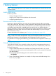
1 Getting Started NOTE: All commands previously in the Summary of commands table are indexed under the entry Command syntax. Initial switch set-up Initial setup includes: • setting a Manager password • assigning an IP (Internet Protocol) address and subnet mask • configuring optional banners Recommended minimal configuration In the factory default configuration, the switch has no IP (Internet Protocol) address and subnet mask, and no passwords.
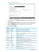
Figure 1 Example Switch Setup screen 3. 4. 5. 6. 7. Use the Tab key to select the Manager Password field and enter a manager password of up to 16 characters. Tab to the IP Config (DHCP/Bootp) field and use the Space bar to select the Manual option. Tab to the IP Address field and enter the IP address that is compatible with your network. Tab to the Subnet Mask field and enter the subnet mask used for your network. Press Enter, then S (for Save).
Table 1 Setup screen field descriptions (continued) Parameter Default Subnet Mask xxx.xxx.xxx.xxx Recommended; If you entered an IP address, then enter a subnet mask compatible with your network.* * The IP address and subnet mask assigned for the switch must be compatible with the IP addressing used in your network. For more on IPv4 addressing, see “Configuring IP Addressing” (page 102). For IPv6 addressing topics, See the latest IPv6 Configuration Guide for your switch.
This command defines the single character used to terminate the banner text and enables banner text input. You can use any character except a blank space as a delimiter. The no form of the command disables the login banner feature. The switch allows up to 3070 banner characters, including blank spaces and CR-LF ([Enter]). (The tilde “~“ and the delimiter defined by banner motd are not allowed as part of the banner text.
Example 2 Show banner motd output HP Switch(config)# show banner motd Banner Information Configured Banner: This is a private system maintained by the Allied Widget Corporation. Unauthorized use of this system can result in civil and criminal penalties! Example 3 Banner in the switch’s running-config file HP Switch (config)# show running Running configuration: ; J8697A Configuration Editor; Created on release #K.15.12.
• If a banner is configured, the switch does not allow configuration with ssh version 1 or ssh version 1-or-2. Attempting to do so produces the following error message in the CLI: Banner has to be disabled first.
The following escape characters are supported: \" double q \’ single quote \` forward quote \\ backslash \f form feed \n newline \r carriage return \t horizontal tab \v vertical tab Example 7 Configuring the banner message using escape characters within double quote delimiters HP Switch(config)# banner motd "You can use the \’banner motd\’ CLI command in non-interactive mode.\n\n\tThe banner motd command will support escape characters.
Example 9 Configuring the banner message using an alternate delimiter of ‘#’ HP Switch(config)# banner motd # Enter TEXT message. End with the character ‘#’ You can use the \’banner motd\’ CLI command in non-interactive mode. \n\n\tThe banner motd command will support escape characters.
2 Using the Menu Interface Overview The menu interface operates through the switch console to provide you with a subset of switch commands in an easy-to-use menu format enabling you to: • Perform a "quick configuration" of basic parameters, such as the IP addressing needed to provide management access through your network • Configure these features: ◦ Manager and Operator passwords ◦ System parameters ◦ IP addressing ◦ Time protocol ◦ Ports ◦ Trunk groups ◦ A network monitoring port ◦ SNM
switch memory manages configuration changes, see Chapter 6, “Switch Memory and Configuration”.) • A configuration change made through any switch interface overwrites earlier changes made through any other interface. • The Menu Interface and the CLI (Command Line Interface) both use the switch console. To enter the menu from the CLI, use the menu command. To enter the CLI from the Menu interface, select Command Line (CLI) option.
Figure 2 Example of the Main Menu with Manager Privileges For a description of Main Menu features, see “Main Menu features” (page 19). NOTE: To configure the switch to start with the menu interface instead of the CLI, go to the Manager level prompt in the CLI, enter the setup command, and in the resulting display, change the Logon Default parameter to Menu. For more information, see the Installation and Getting Started Guide you received with the switch.
Rebooting the switch terminates the menu session, and, if you are using Telnet, disconnects the Telnet session. (See “Rebooting the switch” (page 21).) 3. Exit from the terminal program, turn off the terminal, or close the Telnet application program. Main Menu features The Main Menu gives you access to these Menu interface features: • Status and Counters: Provides access to display screens showing switch information, port status and counters, and port and VLAN address tables.
Figure 4 Elements of the screen structure "Forms" design. The configuration screens, in particular, operate similarly to a number of PC applications that use forms for data entry. When you first enter these screens, you see the current configuration for the item you have selected. To change the configuration, the basic operation is to: 1. Press [E] to select the Edit action. 2. Navigate through the screen making all the necessary configuration changes. (See 20.) 3.
Table 2 How to navigate the Menu interface (continued) Task: Actions: 6. If you are finished editing parameters in the displayed screen, press [Enter] to return to the Actions line and do one of the following: • To save and activate configuration changes, press [S] (for the Save action). This saves the changes in the startup configuration and also implements the change in the currently running configuration. (See Chapter 6, "Switch Memory and Configuration".
Figure 5 The Reboot Switch option in the Main Menu Rebooting to activate configuration changes. Configuration changes for most parameters in the menu interface become effective as soon as you save them. However, you must reboot the switch in order to implement a change in the Maximum VLANs to support parameter. To access this parameter, go to the Main Menu and select: 2. Switch Configuration 8. VLAN Menu 1. VLAN Support.
NOTE: Executing the write memory command in the CLI does not affect pending configuration changes indicated by an asterisk in the menu interface. That is, only a reboot from the menu interface or a boot or reload command from the CLI will activate a pending configuration change indicated by an asterisk.
Where to go from here This chapter provides an overview of the menu interface and how to use it. The following table indicates where to turn for detailed information on how to use the individual features available through the menu interface. Option: Turn to: To use the Run Setup option See the Installation and Getting Started Guide shipped with the switch.
3 Using the Command Line Interface (CLI) Overview The CLI is a text-based command interface for configuring and monitoring the switch. The CLI gives you access to the switch’s full set of commands while providing the same password protection that is used in the web browser interface (WebAgent) and the menu interface. Accessing the CLI Like the menu interface, the CLI is accessed through the switch console, and in the switch’s factory default state, is the default interface when you start a console session.
Example 10 CLI log-on screen with password(s) set HP J8697A Switch 5406zl Software revision K.15.12.0001 Copyright (C) 1991-2013 Hewlett-Packard Development Company, L.P. RESTRICTED RIGHTS LEGEND Confidential computer software. Valid license from HP required for possession, use or copying. Consistent with FAR 12.211 and 12.212, Commercial Computer Software, Computer Software Documentation, and Technical Data for Commercial Items are licensed to the U.S. Government under vendor's standard commercial license.
Operator privileges At the Operator level you can examine the current configuration and move between interfaces without being able to change the configuration. A ">" character delimits the Operator-level prompt. For example: HP Switch>_ (Example of the Operator prompt.) When using enable to move to the Manager level, the switch prompts you for the Manager password if one has already been configured.
Table 3 Privilege level hierarchy — Operator Privilege (continued) Privilege Level Example of Prompt and Permitted Operations link-test enable Move from the CLI interface to the menu interface. menu Move from the CLI interface to the menu interface. logout Exit from the CLI interface and terminate the console session. exit Terminate the current session (same as logout).
Moving between the CLI and the Menu interface. When moving between interfaces, the switch retains the current privilege level (Manager or Operator). That is, if you are at the Operator level in the menu and select the Command Line Interface (CLI) option from the Main Menu, the CLI prompt appears at the Operator level. Changing parameter settings.
Example 12 The Manager-level command listing HP Switch# ? backup boot clear clock Backup next startup-configuration file to TFTP server Reboot the device. Clear table/statistics. Display/set current time, date, and local time parameters. command-alias Specify command alias configure Enter the Configuration context. copy Copy datafiles to/from the switch. debug Enable/disable debug logging. delete Delete a file diagnostic-level Set the diagnostic level. end Return to the Manager Exec context.
HP Switch (config)# portHP Switch (config)# port-security Pressing [Tab] after a completed command word lists the further options for that command. For example, entering HP Switch(config)# qos [Tab] displays the following: HP Switch (config)# qos udp-port Set UDP port-based priority. tcp-port Set TCP port-based p riority. device-priority Configure device-based priority for a particular IP address. dscp-map Define mapping between a DSCP (Differentiated-Services Codepoint) value and an 802.1p priority.
help displays the Help summaries for both the Operator and Manager levels, and so on. For example, to list the Operator-Level commands with their purposes: Example 14 Context-sensitive command-list help HP Switch> help chassislocate dir display enable exit link-test logout . . . Control the chassis locate led. Display a list of the files and subdirectories in a directory on a USB device. Display current system information. Enter the Manager Exec context.
HP HP HP HP Switch(config)# interface c3-c6 Switch(eth-C5-C8)# Switch(config)# interface trk1 Switch(eth-Trk1)# Commands executed at configuration level for entering port and trk1 static trunk-group contexts, and resulting prompts showing port or static trunk contexts. HP HP HP HP Switch(eth-C5-C8)# Switch(eth-Trk1)# Switch(eth-C5-C8)# ? Switch(eth-C5-C8)# ? Lists the commands you can use in the port or static trunk context, plus the Manager, Operator, and context commands you can execute at this level.
HP Switch(vlan-100)# ? Lists commands you can use in the VLAN context, plus Manager, Operator, and context commands you can execute at this level.
The disable option disables prefixing returned messages for the session for which this command is executed. Note: This setting is not saved when the switch is rebooted. Default: Disabled on all CLI sessions Example 16 Message prefixes HP Switch(config)# router rip Error: IP Routing support must be enabled first. HP Switch(config)# qinq mixed vlan Warning: This command will reboot the device.
Example 19 CLI interactive mode enabled HP Switch(config)# show session show message type : Enabled cli interactive mode: Enabled Interactive commands requiring additional options Interactive commands that require input other than yes or no are not affected when CLI interactive mode is disabled. A warning message is displayed when these commands are executed, for example: Interactive mode is disabled; This command will be ignored. Enable cli-interactive-mode to use this command.
CLI control and editing Executing a prior command—redo The redo command executes a prior command in the history list. Syntax: redo [ number | command-str ] Re-executes a command from history. Executes the last command by default. number: The position of the command to execute in the history list. When number is specified, the nth command starting from the most recent command in the history is executed.
Example 21 The repeat command using a range HP Switch(config)# show history 3 show ver 2 show ip 1 show arp HP Switch(config)# repeat 1-2 IP ARP table IP Address -------------15.255.128.
Example 22 Using the alias command with show int custom HP Switch(config)# show int custom 1-4 port name:4 type vlan intrusion speed enabled mdi Status and Counters - Custom Port Status Port ---1 2 3 4 Name -------Acco Huma Deve Lab1 Type ---------100/1000T 100/1000T 100/1000T 100/1000T VLAN ----1 1 1 1 Intrusion Alert --------No No No No Speed ------1000FDx 1000FDx 1000FDx 1000FDx Enabled ------Yes Yes Yes Yes MDI-mode ------Auto Auto Auto Auto HP Switch(config)# alias sic "show int custom 1-4 por
Keystrokes Functions [Ctrl] [D] Deletes the character at the cursor. [Ctrl] [E] Jumps to the end of the current command line. [Ctrl] [F] or ‘→’ Moves the cursor forward one character. [Ctrl] [K] Deletes from the cursor to the end of the command line. [Ctrl] [L] or [Ctrl] [R] Repeats current command line on a new line. [Ctrl] [N] or ‘↓’ Enters the next command line in the history buffer. [Ctrl] [P] or ‘↑’ Enters the previous command line in the history buffer.
4 Using the HP WebAgent Overview The HP web browser interface (WebAgent) built into the switch lets you easily access the switch from a web browser.
General features The WebAgent includes this information: • • • • Home ◦ Quick Setup—Name, contact, IP, and VLAN information ◦ Status—Information about system uptime, switch addresses and serial number, VLANs, power, redundancy status, alert log, and utilization statistics System ◦ Logging—Fault detection, alert log ◦ SNMP—Community name and access, trap receivers, link status change ◦ Updates/Downloads—Configuration files, software images ◦ Redundancy—Management module status, fabric module
• Troubleshooting ◦ Ping/Link Test—Ping test details, link test details ◦ Configuration Report—Running config file information ◦ Core dump—Management/Interface modules enabled/disabled, list of core dump files for downloading ◦ Port Mirroring—Enabled/disabled Figure 10 Example of Status Screen for the WebAgent Starting the WebAgent Port Mirroring—Enabled/disabled • Using a standalone web browser on a network connection from a PC or UNIX workstation that is directly connected to your network or c
10.11.12.195 [Enter] (example of an IP address) The Home page of the WebAgent displays in the right pane and a navigation tree displays in the left pane. You can access all the WebAgent features from the navigation tree. Tasks for your first WebAgent session Viewing the “First Time Install” window When you access the WebAgent for the first time, the Alert log contains a “First Time Install” alert.
1. 2. 3. 4. In the navigation tree, select Security > Device Passwords. The Device Passwords screen displays. Click on Change on the right side of the screen. The pane expands to allow you to enter information. Enter a username, password, and access level. Click on Save to save your entries. NOTE: Passwords assigned in the WebAgent will overwrite previous passwords assigned in either the WebAgent, the CLI, or the menu interface.
Figure 12 Example of WebAgent access from PCM+ 46 Using the HP WebAgent
5 Switch Memory and Configuration Overview This chapter describes: • How switch memory manages configuration changes • How the CLI implements configuration changes • How the menu interface and WebAgent implement configuration changes • How the switch provides software options through primary/secondary flash images • How to use the switch’s primary and secondary flash options, including displaying flash information, booting or restarting the switch, and other topics Configuration file management Th
of the configuration previously defined in the startup-config file. There are three ways to save a new configuration: • In the CLI: Use the write memory command. This overwrites the current startup-config file with the contents of the current running-config file. • In the menu interface: Use the Save command. This overwrites both the running-config file and the startup-config file with the changes you have specified in the menu interface screen. • In the WebAgent: Click on Save.
• write terminal— Displays a listing of the current running-config file. • show default–config— Displays a listing of a custom default config file. • show config status— Compares the startup-config file to the runningconfig file and lists one of the following results: ◦ If the two configurations are the same you will see: – ◦ Running configuration is the same as the startup configuration.
The new mode (auto-10) on port A5 is now saved in the startup-config file, and the startup-config and running-config files are identical. If you subsequently reboot the switch, the auto-10 mode configuration on port A5 will remain because it is included in the startup-config file. NOTE: Beginning with K.15.01.0031, configuration changes to ports may require up to 10 seconds to take effect, especially on switches with high CPU utilization.
NOTE: If you use the CLI to make a change to the running-config file, you should either use the write memory command or select the save option allowed during a reboot (see “Boot prompt for an unsaved configuration” (page 50)) to save the change to the startup-config file.
NOTE: This feature does not change the system defaults. The custom default configuration file is automatically used when the startup configuration file is erased. It has no effect on what is loaded onto the switch when a remotely stored configuration file is restored. The default configuration file can be customized using commands at the CLI prompt or by copying a configuration file with the desired configuration using TFTP, USB, or XMODEM copy commands.
Syntax: copy tftp default-config Copies the stored configuration file on the TFTP server specified by to the custom default configuration file. Example 28 Copying a stored config file to the default config file using TFTP HP Switch(config)# copy tftp default-config 10.10.10.1 stored_config.cfg Using XMODEM To copy a configuration file to the custom default configuration file using XMODEM, use the copy xmodem default-config command.
Syntax: copy default-config xmodem Copies the custom default configuration file to the configuration file specified by the XMODEM server device. Using USB To transfer a custom default configuration file off the switch using USB, enter the following command. Syntax: copy default-config usb stored_config.cfg Copies the custom default configuration file to the stored_config.cfg file on the USB device.
Example 31 Using SFTP C:\PuTTY> psftp 10.1.243.209 We'd like to keep you up to date about: * Software feature updates * New product announcements * Special events Please register your product at: www.register.hp.
Example 34 Erasing the custom default config file HP Switch(config)# erase default-config The custom default configuration will be erased. The "erase startup-config" command will now use system generated default configuration. Continue [y/n]? Displaying the configuration files The show config files command displays the existing configuration files and indicates that a custom default configuration file exists.
Example 36 Output for custom default configuration file HP Switch(config)# show default-config Custom default configuration: ; J8693A Configuration Editor; Created on release #K.15.14.
Using the menu and WebAgent to implement configuration changes configuration file The menu and WebAgent offer these advantages: • Quick, easy menu or window access to a subset of switch configuration features • Viewing several related configuration parameters in the same screen, with their default and current settings • Immediately changing both the running-config file and the startup-config file with a single command Menu: implementing configuration changes You can use the menu interface to simultane
Rebooting from the menu interface • Terminates the current session and performs a reset of the operating system • Activates any configuration changes that require a reboot • Resets statistical counters to zero To Reboot the switch, use the Reboot Switch option in the Main Menu. (Note that the Reboot Switch option is not available if you log on in Operator mode; that is, if you enter an Operator password instead of a manager password at the password prompt.
Figure 16 Indication of a configuration change requiring a reboot WebAgent: implementing configuration changes You can use the WebAgent to simultaneously save and implement a subset of switch configuration changes without having to reboot the switch. That is, when you save a configuration change, you simultaneously change both the running-config file and the startup-config file. For online help with configuring changes in the WebAgent, click on the "?" in the WebAgent screen.
Syntax: erase all [zeroize] Erases all management module files, including configuration files, core dumps, password files, crypto-key files, etc. Software images are not erased. When executed without the zeroize option, files are removed, but the flash storage is not zeroized. The data is still physically present in the flash. The flash can be removed from the switch and the data recovered with file recovery tools. [zeroize]: Zeroizes the file storage of the management modules.
Using Primary and Secondary flash image options The switches covered in this guide feature two flash memory locations for storing switch software image files: • Primary Flash: The default storage for a switch software image. • Secondary Flash: The additional storage for either a redundant or an alternate switch software image. With the Primary/Secondary flash option you can test a new image in your system without having to replace a previously existing image.
Example 41 Different flash image versions HP Switch(config)# show flash Image Size(Bytes) Date -------------- -------Primary Image : 7493854 03/21/10 Secondary Image : 7463821 03/23/10 Version ------------K.15.01.0001 K.15.01.0001 Boot Rom Version: K.15.08 Default Boot : Primary Determining which flash image versions are installed. The show version command displays which software version the switch is currently running and whether that version booted from primary or secondary flash.
Download interruptions. In most cases, if a power failure or other cause interrupts a flash image download, the switch reboots with the image previously stored in primary flash. In the unlikely event that the primary image is corrupted, as a result of an interruption, the switch will reboot from secondary flash and you can either copy the secondary image into primary or download another image to primary from an external source.
For example, to copy the image in secondary flash to primary flash: 1. Verify that there is a valid flash image in the secondary flash location. The following figure indicates that a software image is present in secondary flash. (If you are unsure whether the image is secondary flash is valid, try booting from it before you proceed by using boot system flash secondary.
Example 45 Show flash listing after erasing Primary flash HP Switch# show flash Compressed Primary Code size = 0 Compressed Secondary code size = 2555802 Boot ROM Version : K.15.19 Default Boot : Secondary In redundant management systems, this command will erase the selected flash in both the active and the standby management modules. If redundancy has been disabled or the standby module has failed self-test, this command only affects the active management module.
Table 7 Comparing the boot and reload commands Actions Included in Boot? Included in Reload Note Save all configuration changes since the last boot or reload Optional, with prompt Optional with reload , when prompt displays. Not saved with reload at/after commands; No prompt is displayed. Config changes saved to the startup-config file if "y" is selected (reload command). Perform all system self-tests Yes No The reload command provides a faster system reboot.
Note: This is changed from always booting from primary flash. You are prompted with a message which will indicate the flash being booted from. system: Boots the switch. You can specify the flash image to boot from. When using redundant management, boots both the active and standby management modules. config: You can optionally select a configuration file from which to boot.
Example 49 Boot command with secondary flash option HP Switch(config)# boot system flash secondary System will be rebooted from secondary image. Do you want to continue [y/n]? In the above example, typing either a ‘y’ or ‘n’ at the second prompt initiates the reboot operation. Using the fastboot feature. The fastback command allows a boot sequence that skips the internal power-on self-tests, resulting in a faster boot time.
Enables a scheduled warm reboot of the switch. The switch boots up with the same startup config file and using the same flash image as before the reload. CAUTION: When using redundant management, the reload at/after command causes a switchover at the scheduled time to the other management module, which may not be running the same software image or have the same configurations. Parameters include: • after: Schedules a warm reboot of the switch after a given amount of time has passed.
Syntax: [no] reload [[after <[[DD:]HH:]MM>] | [[at HH:MM[:SS] [MM/DD[/[YY]YY]]]] | [[module ]]] When specified with the module parameter, initiates a reload of the module in the specified slot or slots by turning the slot power off, then on again. A valid slot or range of slots must be specified. The at and after parameters are not allowed with the module option. The no version of the command is not valid with the module option.
Example 53 The scheduled reload at information HP Switch(config)# reload at 23:45 Reload scheduled at 23:45:47 6/16/2012 (in 0 days, 1 hours, 41 minutes HP Switch(config)# show reload at Reload scheduled for 23:45:47 06/16/2012 (in 0 days, 1 hours, 40 minutes) HP Switch(config)# show reload after Reload scheduled for 23:45:47 6/16/2012 (in 0 days, 1 hours, 40 minutes) Example 54 The scheduled reload after information HP Switch(config)# reload after 35 Reload scheduled in 0 days, 0 hours, 35 minutes HP Swit
This choice of which configuration file to use for the startup-config at reboot provides the following new options: • The switch can reboot with different configuration options without having to exchange one configuration file for another from a remote storage location. • Transitions from one software release to another can be performed while maintaining a separate configuration for the different software release versions.
Figure 18 Example of reboot process and making changes to the startup-config file Creating an alternate startup-config file. There are two methods for creating a new configuration file: • Copy an existing startup-config file to a new filename, then reboot the switch, make the desired changes to the running-config file, then execute write memory. (See “Example of reboot process and making changes to the startup-config file” (page 74).) • Erase the active startup-config file.
Example 57 Switch memory assignments after the first reboot from software supporting multiple configuration HP Switch(config)# show config files Configuration files: id | act pri sec | name ---+-------------+----------------------------------------------1 | | oldConfig 2 | * * * | workingConfig 3 | | In the above state, the switch always: • Uses the workingConfig file to reboot The commands described later in this section enable you to view the current multiple configuration status, manage multiple start
Changing or overriding the reboot configuration policy You can boot the switch using any available startup-config file. Changing the reboot configuration policy. For a given reboot, the switch automatically reboots from the startup-config file assigned to the flash location (primary or secondary) being used for the current reboot.
the switch boots from secondary flash, the operator also wants the startup-config named newconfig to be used. The following two commands configure the desired behavior. HP Switch(config)# startup-default pri config minconfig HP Switch(config) # startup-default sec config newconfig Overriding the default reboot configuration policy. This command provides a method for manually rebooting with a specific startup-config file other than the file specified in the default reboot configuration policy.
place, you can easily reboot the switch with the correct startup-config file for either software version. • If the destination startup-config file already exists, it is overwritten by the content of the source startup-config file. • If the destination startup-config file does not already exist, it will be created in the first empty configuration memory slot on the switch.
This option erases the specified startupconfig file. If the specified file is not the currently active startup-config file, then the file is simply deleted from the memory slot it occupies. If the specified file is the currently active startup-config file, then the switch creates a new, default startup-config file with the same name as the erased file, and boots using this file. (This new startup-config file contains only the default configuration for the software version used in the reboot.
Using the Clear + Reset button combination to reset the switch to its default configuration The Clear + Reset button combination described in the Installation and Getting Started Guide produces these results. That is, when you press the Clear + Reset button combination, the switch: • Overwrites the content of the startup-config file currently in memory slot 1 with the default configuration for the software version in primary flash, and renames this file to config1.
data interface. The oobm parameter is not available on switches that do not have a separate out-of-band management port. Note: This command requires an empty memory slot in the switch. If there are no empty memory slots, the CLI displays the following message: Unable to copy configuration to "". You can erase one or more configuration files using the erase config command.
Syntax: show running-config [interface | vlan vlan-id-list] [structured] Displays running configuration information about the selected interface when one is specified. The interfaces can be ports, VLANs, or SVLANs. Note: For the 5400zl, 3800, and 8200zl switches, when the command is executed in enhanced secure mode the following prompt displays: Do you want to show sensitive information(y/n)? If ‘y’ is entered, the normal command output is displayed on the console.
Example 62 Running configuration output for interfaces A2 - A4 HP Switch(eth-A2-A4)# show running-config Running configuration: ; J8698A Configuration Editor; Created on release #K.15.10.
Example 63 Running config output for a specified interface range HP Switch(config)# show running-config interface A2-A3 Running configuration: interface A2 disable name "test1" flow-control broadcast-limit 80 speed-duplex 100-full unknown-vlans block qos priority 4 gvrp join-timer 30 leave-timer 60 leaveall-timer 700 dhcp-snooping trust lacp passive bandwidth-min output 20 10 10 10 20 10 10 10 rate-limit bcast in percent 75 ipv6 access-group "check" in untagged vlan 1 exit interface A3 disable name "test1"
Example 64 Running config output for a range of interfaces HP Switch(config)# no stack HP Switch(config)# mesh 2-3 Command will take effect after saving configuration and reboot. HP Switch(config)# write memory HP Switch(config)# reload HP Switch# show running-config interface 2-3 Running configuration: interface 2 untagged vlan 1 mesh exit interface 3 flow-control untagged vlan 1 mesh exit The example below is an example of the running config output showing VLAN information.
Example 65 Running config output showing VLAN information HP Switch(config)# show running-config Running configuration: ; J8698A Configuration Editor; Created on release #K.15.10.0001 ; Ver #02:0b:ef:e6 hostname "HP Switch" module 1 type J9309A module 3 type J8702A module 6 type J8702A ip routing vlan 1 name "DEFAULT_VLAN" untagged A1-A4,C1-C24,F1-F24 ip address dhcp-bootp exit vlan 2 name "test-vlan-2" ip helper-address 4.1.1.1 ip helper-address 5.1.1.1 ip address 1.1.1.1 255.255.255.
Example 66 Running config output for a range of VLANs HP Switch(config)# show running-config vlan 3-4 Running configuration: vlan 3 name "VLAN3" ip helper-address 7.1.1.1 ip forward-protocol udp 7.1.1.1 snmp ip forward-protocol udp 11.1.1.2 dns no ip address exit vlan 4 name "VLAN4" ip address 5.1.1.1 255.255.255.0 ip bootp-gateway 5.1.1.1 ip route 5.1.1.0 255.255.255.
Note: For the 5400zl, 3800, and 8200zl switches, when the command is executed in enhanced secure mode the following prompt displays: Do you want to show sensitive information(y/n)? If ‘y’ is entered, the normal command output is displayed on the console. If ‘n’ is entered, all the sensitive information is hidden and will be displayed as asterisks (‘*****’). The default option is ‘n’ when interactive mode is disabled.
Example 70 Startup config output for a range of interfaces for a specific VLAN HP Switch(vlan-5)# show config interface C10-C13 Startup configuration: interface C10 untagged vlan exit interface C11 untagged vlan exit interface C12 untagged vlan exit interface C13 untagged vlan exit 5 5 5 5 Automatic configuration update with DHCP Option 66 HP switches are initially booted up with the factory-shipped configuration file.
Possible scenarios for updating the configuration file The following table shows various network configurations and how Option 66 is handled. Scenario Single Server serving Multiple VLANs Behavior • Each DHCP-enabled VLAN interface initiates DHCPDISCOVER message, receives DHCPOFFER from the server, and send DHCPREQUEST to obtain the offered parameters. • If multiple interfaces send DHCPREQUESTs, it’s possible that more than one DHCPACK is returned with a valid Option 66.
6 Interface Access and System Information Interface access: console/serial link, web, and inbound telnet The interface access features in the switch operate properly by default. However, you can modify or disable access features to suit your particular needs. Similarly, you can choose to leave the system information parameters at their default settings. However, modifying these parameters can help you to more easily distinguish one device from another in your network.
Example 71 Listing of show console command HP Switch (config)# show console Console/Serial Link Inbound Telnet Enabled [Yes] : Yes Web Agent Enabled [Yes] : Yes Terminal Type [VT100] : VT100 Screen Refresh Interval (sec) [3] : 3 Displayed Events [All] : All Baud Rate [speed-sense] : speed-sense Flow Control [XON/XOFF] : XON/XOFF Global Session Idle Timeout (sec) [0] : 0 Serial/USB Console Idle Timeout (sec) [not set] : not set Current Session Idle Timeout (sec) : 0 Reconfigure inbound telnet access In the
• Hostname • Stack number of a member switch (1-16) if the switch is a commander in a stack and stacking is enabled For switches that have a separate out-of-band management port, the oobm parameter specifies that the Telnet traffic will go out from the out-of-band management interface. If this parameter is not specified, the Telnet traffic goes out from the data interface. The oobm parameter is not available on switches that do not have a separate out-of-band management port.
window dimensions, it refuses them and the telnet client requests an alternate set of window dimensions. The negotiation continues until the telnet client and the switch agree on the window dimensions. The switch currently responds to a request from the remote telnet client to negotiate window size. However, some telnet clients do not request to negotiate window size unless the switch’s telnet server suggests that NAWS is available.
Example 73 WebUI idle timeout HP-5406zl(config)# web-management idle-timeout Set the idle timeout for web management sessions. management-url Specify URL for web interface [?] button. plaintext Enable or disable the http server (insecure). ssl Enable or disable the https server (secure). support-url Specify URL for web interface support page. HP-5406zl(config)# web-management idle-timeout <300-7200> Enter an integer number.
NOTE: If the console idle-timeout expires, any outbound Telnet or SSH sessions open on the switch are terminated. If you change the Baud Rate or Flow Control settings, you should make the corresponding changes in your console access device. Otherwise, you may lose connectivity between the switch and your terminal emulator due to differences between terminal and switch settings for these two parameters.
NOTE: In software release versions K.15.12 and greater, the console inactivity-timer command has been deprecated and replaced by the console idle-timeout command. As an example: HP Switch(config)#console inactivity-timer 2 is now equivalent to: HP Switch(config)#console idle-timeout 120 In addition, the serial or USB console idle timeout can be controlled separately if needed. The console idle-timeout serial-usb seconds command allows for this behavior.
Figure 19 Example of using the kill command to terminate a remote session System information System information features: Feature Default System Name switch product name System Contact n/a System Location n/a MAC Age Time 300 seconds Time Sync Method None Time Zone 0 Daylight Time Rule None Time January 1, 1990 at 00:00:00 at last power reset Configuring system information is optional, but recommended.
System Name: Using a unique name helps you to identify individual devices where you are using an SNMP network management tool such as HP PCM+. System Contact and Location: This information is helpful for identifying the person administratively responsible for the switch and for identifying the locations of individual switches. MAC Age Time: The number of seconds a MAC address the switch has learned remains in the switch’s address table before being aged out (deleted).
Figure 20 System information listing after executing the preceding commands Reconfigure the MAC age time for learned MAC addresses. This command corresponds to the MAC Age Interval in the menu interface, and is expressed in seconds. Syntax: mac-age-time <10-1000000> (seconds) Allows you to set the MAC address table’s age-out interval. An address is aged out if the switch does not receive traffic from that MAC address for the age-out interval, measured in seconds. Default: 300 seconds.
HP Switch(config)# time 9:45 11/17/12 NOTE: Executing reload or boot resets the time and date to their default startup values.
7 Configuring IP Addressing Overview You can configure IP addressing through all of the switch’s interfaces. You can also: • Easily edit a switch configuration file to allow downloading the file to multiple switches without overwriting each switch’s unique gateway and VLAN 1 IP addressing. • Assign up to 32 IP addresses to a VLAN (multinetting). • Select an IP address to use as the source address for all outgoing traffic generated by a specified software application on the switch.
value provided by the DHCP or Bootp server will be used. If the switch has a manually configured default gateway, then the switch uses his gateway, even if a different gateway is received via DHCP or Bootp on the primary VLAN. This is also true for manually configured TimeP, SNTP, and Time-To-Live(TTL). (In the default configuration, VLAN 1 is the Primary VLAN.) See the information on Primary VLANs in the Advanced Traffic Management Guide for your switch. Packet Time-To-Live (TTL).
Menu: configuring IP address, Gateway, and Time-To-Live (TTL) Do one of the following: • To manually enter an IP address, subnet mask, set the IP Config parameter to Manual and then manually enter the IP address and subnet mask values you want for the switch. • To use DHCP or Bootp, use the menu interface to ensure that the IP Config parameter is set to DHCP/Bootp, then see“DHCP/Bootp operation” (page 109). To configure IP addressing. 1. From the Main Menu, select: 2. Switch Configuration... 5.
Example 76 The switch’s default IP addressing HP Switch> show ip Internet (IP) Service IP Routing : Disabled Default Gateway Default TTL Arp Age Domain Suffix DNS server : : 64 : 20 : : | Proxy ARP VLAN | IP Config IP Address Subnet Mask Std Local --------------------- + ---------- --------------- -------------- ---------DEFAULT_VLAN | DHCP/Bootp With multiple VLANs and some other features configured, show ip provides additional information: Example 77 Show IP listing with non-default IP addressing confi
This example configures IP addressing on the default VLAN with the subnet mask specified in mask bits. HP Switch(config)# vlan 1 ip address 10.28.227.103 255.255.255.0 This example configures the same IP addressing as the preceding example, but specifies the subnet mask by mask length. HP Switch(config)# vlan 1 ip address 10.28.227.103/24 This example deletes an IP address configured in VLAN 1. HP Switch (config) no vlan 1 ip address 10.28.227.
Example 78 Configuring and displaying a multinetted VLAN HP Switch(config)# vlan 20 HP Switch(vlan-20)# ip address 10.26.33.101/20 HP Switch(vlan-20)# ip address 10.27.33.101/20 HP Switch(config)# show ip Internet (IP) Service IP Routing : Disabled Default Gateway Default TTL Arp Age Domain Suffix DNS server : 10.20.227.1 : 64 : 20 : : VLAN ------------------DEFAULT_VLAN VLAN_20 | | + | | | | IP Config ---------Manual Manual Manual Manual IP Address Subnet Mask --------------- -------------10.20.30.
Syntax: ip default-gateway For example: HP Switch(config)# ip default-gateway 10.28.227.115 NOTE: The switch uses the IP default gateway only while operating as a Layer 2 device. While routing is enabled on the switch, the IP default gateway is not used. Thus, to avoid loss of Telnet access to off-subnet management stations, you should use the ip route command to configure a static (default) route before enabling routing.
Table 8 Features available with and without IP addressing on the switch (continued) Features available without an IP Address Additional features available with an IP Address and subnet mask • Console-based status and counters information for monitoring switch operation and diagnosing problems through the CLI or menu interface • TACACS+, RADIUS, SSH, SSL, and 802.
provided by the server may be different each time the switch reboots or renews its configuration from the server. However, you can fix the address assignment for the switch by doing either of the following: • Configure the server to issue an “infinite” lease. • Using the switch’s MAC address as an identifier, configure the server with a “Reservation” so that it will always assign the same IP address to the switch. (For MAC address information, See Appendix D, “MAC Address Management”.
T144 is the vendor-specific "tag" identifying the configuration file to download. vm is a required entry that specifies the Bootp report format. Use rfc1048 for the switches covered in this guide. NOTE: The above Bootp table entry is a sample that will work for the switch when the appropriate addresses and file names are used. Network preparations for configuring DHCP/Bootp In its default configuration, the switch is configured for DHCP/Bootp operation.
User-defined loopback addresses provide the following benefits: • A loopback interface is a virtual interface that is always up and reachable as long as at least one of the IP interfaces on the switch is operational. As a result, a loopback interface is useful for debugging tasks since its IP address can always be pinged if any other switch interface is up. • You can use a loopback interface to establish a Telnet session, ping the switch, and access the switch through SNMP, SSH, and HTTP (WebAgent).
Example 80 A loopback interface configuration HP Switch(config)# interface loopback 1 HP Switch(config)# ip address 10.1.1.1 NOTE: • You can configure a loopback interface only from the CLI; you cannot configure a loopback interface from the WebAgent or Menu interface. • Loopback interfaces share the same IP address space with VLAN configurations.
Example 82 The show ip command output HP Switch# show ip IP Routing : Enabled Default Gateway Default TTL Arp Age Domain Suffix DNS server : 15.255.128.1 : 64 : 20 : : | VLAN | IP Config IP Address Subnet Mask ---------------- + ---------- --------------- -------------DEFAULT_VLAN | Manual 10.0.8.121 255.255.0.0 VLAN2 Manual 192.168.12.1 255.255.255.0 VLAN3 Disabled Loopback -------lol lo2 lo2 IP Config ---------Manual Manual Manual Loopback Addresses IP Address -----------------172.16.110.2 172.16.
Operating rules for IP preserve When ip preserve is entered as the last line in a configuration file stored on a TFTP server: • If the switch’s current IP address for VLAN 1 was not configured by DHCP/ Bootp, IP Preserve retains the switch’s current IP address, subnet mask, and IP gateway address when the switch downloads the file and reboots. The switch adopts all other configuration parameters in the configuration file into the startup-config file.
Example 85 Configuration file in TFTP server with DHCP/Bootp specified as the IP addressing source HP Switch(config)# show run Running configuration: ; J9091A Configuration Editor; Created on release #K.15.10.0001 hostname "HP Switch" module 1 type J8702A module 2 type J8705A trunk A11-A12 Trk1 Trunk ip default-gateway 10.10.10.
Example 86 Configuration file in TFTP server with dedicated IP addressing, instead of DHCP/Bootp HP Switch# show run Running configuration: ; J9091A Configuration Editor; Created on release #K.15.10.0001 hostname "HP Switch" module 1 type J8702A module 2 type J8705A trunk A11-A12 Trk1 Trunk ip default-gateway 10.10.10.115 snmp-server community "public" Unrestricted vlan 1 name "DEFAULT_VLAN" untagged A1,A7-A10,A13-A24,B1-B24,Trk1 ip address 10.12.17.175 255.255.255.
and outgoing packets can potentially be sent by different paths at different times. This results in different source IP addresses, which creates a client identification problem on the server site. For example, there is no way to designate a fixed IP address for outgoing packets for RADIUS or TACACS, so it is necessary to configure in the RADIUS or TACACS database all possible IP addresses that are configured on the switch as valid clients.
The source IP selection policy The source IP address selection for the application protocols is defined through assignment of one of the following policies: • Outgoing Interface—the IP address of the outgoing IP interface is used as the source IP address. This is the default policy and the default behavior of applications. • Configured IP Address—the specific IP address that is used as the source IP address.
Example 89 Using a VLAN interface as the source IP address for TACACS HP Switch(config)# ip source-interface tacacs vlan 22 HP Switch(config)# show ip source-interface tacacs Source-IP Configuration Information Protocol | Admin Selection Policy IP Interface IP Address -------- + ----------------------- -------------- -------------Tacacs | Configured IP Interface vlan 22 10.10.10.4 The next example shows a VLAN interface being specified as the source IP address for logging.
Example 92 The show ip source-interface command Output HP Switch(config)# show ip source-interface Source-IP Configuration Information Protocol -------Tacacs Radius Syslog Telnet Tftp Sntp Sflow | + | | | | | | | Admin Selection Policy ----------------------Configured IP Interface Configured IP Address Configured IP Interface Outgoing Interface Outgoing Interface Outgoing Interface Outgoing Interface IP Interface IP Address ------------- --------------vlan 22 10.10.10.
Example 93 Detailed information displayed for each protocol HP Switch(config)# show ip source-interface detail Source-IP Detailed Information Protocol : Tacacs Admin Policy Oper Policy Source IP Interface Source IP Address Source Interface State : : : : : Configured IP Interface Configured IP Interface vlan 22 10.10.10.4 Up Protocol : Radius Admin Policy Oper Policy Source IP Interface Source IP Address Source Interface State : : : : : Configured IP Address Configured IP Address vlan 3 10.10.10.
Example 94 The show radius command displaying source IP selection information HP Switch(config)# show radius Status and Counters - General RADIUS Information Deadtime(min) : 0 Timeout(secs) : 5 Retransmit Attempts : Global Encryption Key Dynamic Authorization Source IP Selection : 3 : UDP Port : 3799 Configured IP address Example 95 The show tacacs command displaying source IP selection information HP Switch(config)# show tacacs Status and Counters - TACACS Information Timeout : 5 Source IP Selection : Co
Example 99 The sflow agent information HP Switch(config)# show Version : Agent Address : Source IP Selection : sflow agent 1.3;HP;K.15.14.0000x 10.1.1.1 Configured IP Interface Error messages The following error messages may appear when configuring source IP selection if the interface does not exist, is not configured for IP, or is down.
8 Software Management Downloading switch documentation and software from the web You can download software updates and the corresponding product documentation from the HP Networking website. Check the website frequently for the latest software version available for your switch. Viewing or downloading the software manual set Go to: www.hp.com/networking/support Downloading software updates for your switch HP periodically provides switch software updates through the HP Networking website (www.hp.
continue[y/n]? Y 03125K 2. When the switch finishes downloading the software file from the server, it displays the progress message Validating and Writing System Software to FLASH... 3. When the CLI prompt re-appears, the switch is ready to reboot to activate the downloaded software: a. Use the show flash command to verify that the new software version is in the expected flash area (primary or secondary) b.
3. Execute the terminal emulator commands to begin the Xmodem transfer. For example, using HyperTerminal: a. Click on Transfer, then Send File. b. Type the file path and name in the Filename field. c. In the Protocol field, select Xmodem. d. Click on the Send button. The download can take several minutes, depending on the baud rate used in the transfer. 4. 5. 6. If you increased the baud rate on the switch (1), use the same command to return it to its previous setting.
After the switch reboots, it displays the CLI or Main Menu, depending on the Logon Default setting last configured in the menu’s Switch Setup screen. 4. Verify the software version by displaying the system information for the switch (for example, through the show system-information command), and viewing the Software revision field.
NOTE: The allow-no-signature option is available on switches that support non-signed legacy software releases and should be used with caution. To determine support for your switch, go to: www.hp.com/networking/swvalidation. Important: Best Practices for software updates NOTE: With version K.15.01.0031 and later software, you will notice a slight change in the versioning system.
7. 8. Verify that your images and configuration are set correctly. Reload the switch. After following these steps, you should end up with the following results: • Primary image will hold the new software image you want to install (for example, K.15.01.0031) • Secondary image will hold the image you are currently running (for example, K.14.47) • Primary image will boot with Config1 (config file corresponding to new software version—in this example, K.15.01.
Switch1# copy config config1 config config2 Switch1# show config files Configuration files: id | act pri sec | name ---+-------------+----------------------------1 | * * * | config1 2 | | config2 3 | | 3. Save the current config to a tftp server using the copy tftp command. For example: Switch1# copy startup-config tftp 10.1.1.60 Switch1_config_K_14_47.
Switch1# show version Image stamp: /sw/code/build/btm(t4a) Nov 6 2009 13:20:26 K.14.47 188 Boot Image: Primary Switch1# show flash Image Size(Bytes) ---------------Primary Image : 11537788 Secondary Image : 9839140 Boot Rom Version: K.15.09 Default Boot : Primary Date ------04/23/10 11/06/09 Version ------K.15.01.0031 K.14.47 Switch1# show config files Configuration files: id | act pri sec | name ---+-------------+----------------------------1 | * * | config1 2 | * | config2 3 | | 8.
Rolling back switch software If you have followed the update procedures documented in the previous section, you should be able to revert to your previous configuration and software version using the steps below. CAUTION: Long usernames and passwords. Software versions K.15.01.0032 and later support the longer usernames and passwords introduced in K.14.59.
Viewing or transferring alternate configuration files Viewing or copying an alternate configuration saved to the switch will always be accomplished through the software currently running on the switch. This may result in a misleading portrayal of the configuration. For example, if a configuration is created on K.14.47 and saved as config2, and if it is then viewed or transferred while the switch is running K.15.01.0031, it will appear as though K.15.01.0031 has converted the configuration.
Administrators using this feature can schedule such commands as enabling or disabling ports, turning on or off LEDs and Power-Over-Ethernet commands. Syntax HP_Switch# (config) job at job at [HH:]MM [on [MM/]DD][config-save] job at [config-save] no job Schedules a command that will run automatically in the date and time given. Jobs can be scheduled to run on a recurring basis or after certain events.
Example 100 A pair of jobs that disable PoE during non-working hours. Switch(config)# job poe-on at 8:00 on mon-fri config-save "interface 1-24 power-over-ethernet" Switch(config)# job poe-off at 17:00 on mon-fri config-save "no interface 1-24 power-over-ethernet" Example 101 A pair of jobs that block access to a server during weekends. Switch(config)# ip access-list extended block-server Switch(config-ext-nacl)# deny ip any host 10.0.1.
Example 104 Job scheduler show command HP-2620-48-PoEP# show job Job Scheduler Status and Configuration Scheduler Status : Waiting for the system time to be set Event or Save Name Time Cfg Command -------------------- ------------- ---------------------------------------Burrrrrrrrrrrrrrr...
Adjustment of more than 10 minutes are considered a major change and reset the Job Scheduler. Any jobs scheduled during a time clock jump forward are skipped while any jobs scheduled during a time clock jump back are repeated. Calendar Conflicts Because the Job Scheduler MIB is more flexible than the CLI scheduling grammar, it is possible to create job schedules via SNMP that can’t be displayed by the CLI. The following rules are imposed on MIB values to limit them to what the CLI can display. 1.
9 Daylight Saving Time on HP Switches This information applies to the following HP switches: • 212M • Series 2500 • Series 3400cl • Series 5300xl • 224M • Series 2510 • Series 3500 • Series 5400zl • 1600M • Series 2600 • Series 3500yl • Switch 6108 • 2400M • Series 2610 • Series 3600 • Switch 6200yl • 2424M • Series 2620 • Series 3800 • Series 6400cl • 4000M • Series 2800 • Series 4100gl • Switch 6600 • 8000M • Switch 2910 • Series 4200vl • Series 8200zl • HP AdvanceStack Switches
Figure 22 Menu interface with "user-defined" daylight time rule option Before configuring a "User defined" daylight time rule, it is important to understand how the switch treats the entries. The switch knows which dates are Sundays and uses an algorithm to determine on which date to change the system clock, given the configured "Beginning day" and "Ending day": • If the configured day is a Sunday, the time changes at 2 am on that day.
10 Power-Saving Features Overview There are several power-saving features that can be configured for the indicated switches and modules. The power-saving features include the ability to: • Turn slot power on or off • Turn LED power on or off • Turn slot auto low power mode on or off • Use LLDP for Energy Efficient Ethernet The modules support the power-saving features as indicated in the table below.
Configures power-saving features. module [ slot-list | all ] Turns power-saving options on or off for modules. led [ slot-list | all ] Turns power-saving options on or off for the LEDs for a module, list of modules or all modules. port-low-pwr [ slot-list | all ] Enables or disables auto power down for slots. Configuring the savepower module option The module option provides the ability to turn the slot power on or off. If no module is specified, all slots are powered off.
NOTE: If a savepower module slot-list or savepower module all command is immediately followed by a no savepower module slot-list or no savepower module all command, the first slot in the list is powered down and then brought up. Configuring the savepower LED option The savepower LED option provides the ability to turn off specified slot LEDs or all LEDs. You can also configure a timer for turning off the chassis LEDs or the specified slot LEDs.
Figure 25 Example of setting a time and duration for savepower led command Configuring the savepower port-low-pwr option The port-low-pwr option puts the slots into auto low power mode if they are not linked. If a particular slot is specified, only that slot goes into auto low-power mode. Specifying savepower port-low-pwr all puts all the slots into auto low power mode. (See Figure 26 (page 144).) The ports in low-power mode periodically monitor to determine if the link has become active.
Figure 27 Example of output for show savepower module command show savepower port-low-pwr Displays the status of the power-down feature for the slots (see Figure 28 (page 145).) For the stackable switches, the output shows if the feature is enabled or not enabled. Figure 28 Example of output for show savepower port-low-pwr command show savepower led Displays the configured status of the LED power-saving option (see Figure 29 (page 145).
Enabling energy efficient ethernet Energy efficient ethernet (EEE) follows the 802.3az standard, which provides support for a system to operate in low-power idle mode during low-link use. This allows both sides of a link to disable or turn off a portion of the system's transmit/receive circuitry, saving power. When traffic is ready for transmission, the interface sends a "wake-up" message to the link partner to prepare to receive the traffic. The circuitry is returned to "normal" mode.
The parameters are explained in the following table. Parameter Description EEE Config The EEE configuration status, read from the configuration database. • Enabled EEE mode is enabled. • Disabled EEE mode is disabled. Current Status Current EEE operational status. • Active The port is advertised and auto-negotiated EEE with link partner (an EEE-capable partner.) EEE mode is enabled. • Inactive Set to one of the following conditions: • EEE configuration is disabled on the local port.
Examples Figure 31 Configuring Layer 2 TLVs on a port To display the EEE TLV information for the local port, enter the show lldp info local-device port-list command, as shown in Figure 32 (page 148). Figure 32 Output for LLDP information for a local port To display the EEE TLV information for the link partner, enter the show lldp info remote-device port-list command.
11 Product Licensing, Support, Documentation and Resources Product licensing The general procedure forinstalling a software license involves several different numbers: • Registration ID — This number comes with the license you purchase, and represents your right to install the particular type of license on a particular type of switch.
Premium License: Supports advanced routing features, including: • OSPFv2, OSPFv3 • PIM Sparse Mode, PIM Dense mode • VRRP • QinQ (IEEE 802.1ad) • BGP (starting with K.15.06.0006) • VRRPv3 (starting with K.15.13.0003) NOTE: • All HP 3500, 3500yl, and 6600 series switches require a Premium License for the features listed above. • All HP 6200yl series switches include the features listed above (a Premium License is not required).
Table 9 Applicable Products (continued) Product Part Number HP Switch E3500-48-PoE J9473A HP Switch E6200yl-24G mGBIC Premium Edge J8992A HP Switch E3500yl 2p 10GbE X2 + 2p CX4 Module J8694A HP Switch E3500yl/E6200yl Fan Tray 5069-8598 HP Switch E3500yl/E6200yl Rack Mounting Kit 5069-5705 HP Switch E3500yl/E6200yl 10K Rack Rail Kit 356578-B21 HP Switch zl and yl RPS/EPS Cable 5070-0102 HP Switch 2530-48G-PoE+ J9772A HP Switch 2530-24G-PoE+ J9773A HP Switch 2530-8G-PoE+ J9774A HP Switch
To set up and install the switch in your network Physical installation Use the Installation and Getting Started Guide, available at www.hp.com/support: • Notes, cautions, and warnings related to installing and using the switch and its related modules. • Instructions for physically installing the switch in your network. • Quickly assigning an IP address and subnet mask, setting a Manager password, and (optionally) configuring other basic features. • Interpreting LED behavior.
Related documentation The following sources provide related information: • Power over Ethernet (PoE/PoE+) Planning and Implementation Guide • HP Switch 620 Redundant and External Power Suppy Installation and Getting Started Guide • HP Switch 630 Redundant and/or External Power Supply Installation and Getting Started Guide You can also find the documents referenced in this guide on the Manuals page of the HP Business Support Center website: http://www.hp.com/support/manuals.
• Braces ( ) enclose required elements. • Braces within square brackets ( [ ] ) indicate a required element within an optional choice. • Boldface indicates use of a CLI command, part of a CLI command syntax, or other displayed element in general text. For example: "Use the copy tftp command to download the key from a TFTP server." • Italics indicate variables for which you must supply a value when executing the command.
Contacting HP support HP customer support services If you are having trouble with your switch, Hewlett-Packard offers support 24 hours a day, seven days a week through the use of a number of automated electronic services. See the Customer Support/Warranty booklet that came with your switch for information on how to use these services to get technical support. HP provides up-to-date customer care, support, and warranty information at www.hp.com/networking/support.
Index A alias command, 38 ARP arp age, default, 104 asterisk meaning in show config, 75 B banner configuring, 11 default, 10 exec option, 13 non-default, 10 operation, 10 redundant management, 10 user-configurable, 13 basic switch configuration IP address, 9 manager password, 8 Switch Setup screen, 8 Best Offer, 90 Boot command reboot, 66 boot command reboot command reload, 47 Bootp, 109 see also DHCP bootp automatic switch configuration, 8 Bootp table file, 110 Bootptab file, 110 operation, 109, 110 serve
rename config, 77 repeat, 37 session interactive-mode, 35 show-message-type, 34 show config, 75, 87 config files, 75 console, 91 fastboot, 69 interfaces, 153 ip, 104 ip source-interface, 120, 121 running-config, 82 system information, 99 version, 62 show job, 136 snmp-server, 99 startup-default, 76 telnet, 92 time, 100 web-management, 94 write memory, 49 config files oobm, 80 configuration Bootp, 110 comparing startup to running, 48 console, 91 custom default config, 51 DHCP Option 66, 89 DHCP, Best Offer,
manager level, 27 moving between contexts, 29 port or trunk-group, 32 VLAN-specific, 33 copy custom config file, 51 multiple config file, tftp, 80 D date, configure, 100 default custom config file, 51 default gateway, 102 see also gateway default settings banner, 10, 12 baud rate speed sense, 91 boot flash primary, 66 configuration file name switch.
interactive mode, CLI, 35 IP CLI access, 104 configuration, 102 DHCP/Bootp, 102 effect when address not used, 108 features available with and without, 108 gateway, 102 gateway (IP) address, 103 menu access, 104 multinetting, 102 multiple addresses in VLAN, 102, 106 single source addressing, 118 source IP address, 118 source-interface command, 119 subnet, 102, 105 subnet mask, 102, 104 Time-To-Live, 104 TTL, 104 IP address Configured IP address, 119 Configured IP interface, 119 displaying source IP informati
ProCurve switch documentation, 152 R reboot faster boot time, 69 scheduling remotely, 69 via menu interface, 21 redo, command description, 37 reload command, 66 modules (5400, 8200), 70 remote session, terminate, 97 repeat, command description, 37 reset operating system, 21 rolling back switch software, 133 router gateway, 104 router, hop, 108 running-config show for VLANs, 81 viewing, 48 see also configuration S savepower led option, 143 port-low-pwr, 144 show led, 145 show module, 144 show port-low-pwr,
subnet, 102, 105 VLAN ID see VLAN VT-100 terminal, 91 W warranty, 1 web agent disabling access, 41 enabled parameter, 41 web browser interface access configuration, 91 access parameters, 44 access security, 91 disable access, 41 enabling, 43 fault detection policy, 44 first-time install, 44 Java applets, enabling, 43 password lost, 45 password, setting, 45 security, 41, 44 standalone, 43 system requirements, 43 web-management listen, oobm, 95 oobm, 95 Web-management idle timeout WebUI idle timeout, 94 writ