
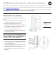
HP 5400R zl2 Quick Setup Guide and Safety/Regulatory Information


1
HP 5400R zl2 Switches Quick Setup Guide and Safety/Regulatory Information
The drawings used in this document are for illustration purposes only and may not exactly match your particular switch.
For complete installation instructions, see the
HP 5400R zl2 Installation and Getting Started Guide on the HP Networking Web
site at: www.hp.com/networking/support
Auto search on “zl modules,” and select your module from the list. Click Display selected, and then click on the links that
have Manuals listed to get on to the webpage that lists the available manuals.
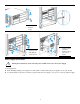
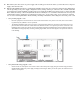
Rack mounting instructions
(These drawings show a 6-slot chassis, but the
procedures are the same for the 12-slot chassis.)
Before installation, read “Installation Precautions” on
page 4.
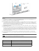
1. Determine position of switc
h in rack and install a cage
nut in the lower hole of the lowest rack unit.
2. Install a screw half-way
into this cage nut.
3. Align the included Rack Mount Bracket suc
h that the
half-hole lines up with the screw, install additional cage
nuts at each hole position in the bracket.
4. Repeat for opposite col
umn in the rack.
5. Secure the Rack Mount Brackets
to the switch with
included flat head screws.
Note: Use only the included 6 mm/0.24 inch flat
head screws. Using any of the 8 mm/0.31 inch
screw included in other rack mounting kits
interferes with internal components.
6. Rest the switch on the two half-way installed screws
and secure the switch to the rack using the top hole in
each Rack Mount Bracket.
7. Align each Cable Manager such that two holes in the
Cable Manager align with two empty holes in the Rack
Mount Bracket and secure with two screws.
8. Snap the Cable Retainers into the arms of the Cable
Ma
nagers.
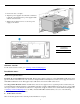
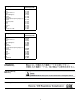
1.
1 0.625 inch (1.588
cm)
2 0.50 inch (1.27
cm)
2.