
HP StorageWorks 4Gb SAN Director Port Blade Installation Instructions (A7990-90003, November 2006)


Chassis configuration setting
When migrating a SAN Director with two doma ins (two logical
switches) to a 4/256 SAN Director , the result will be a SAN Director
with only one domain. Depending on your configuration, this
may change the topology of the fabric and should be taken into
consideration when planning your installation.
The 4/256 SAN Director supports chassis configuration options 1 or
5only. UsethechassisConfig command to change the chassis
configuration. The valid options are:
• Option 1 — One (up to) 128-port logical switch. This chassis mode
supports CP4 control processor blades managing FC4–16.
• Option 5 — One (up to) 384-port logical switch. This chassis mode
supports CP4 control processor b lades managin g the FC4–16,
FC4–32, and FC4–48.
Blade components and port numbering
The following sections illustrate 4Gb SAN Director Port Blade
components.
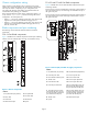
FC4–16 Port Blade components
Figure 1 identifies FC4–16 blade components and the port numbering
scheme. P
orts are numbered from 0 through 15 from bottom to top.
15
14
13
12
11
10
56-0000590-01 Rev A
!
7
6
5
4
3
2
1
0
15
14
13
12
11
10
9
8
56-0000590-01 Rev A
!
FC4
16
1
2
3
4
5
6
7
8
25027a
Figure 1 FC4–16 components
Callouts
1. On/Off switch (On position)
5. Port speed LED
2. Power LED
6. Port status LED
3. Status LED
7. Thumb screw
4. Fibre Channel port
8. Ejector
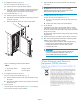
FC4–32 and FC4–4
8 Port Blade components
Figure 2 identif
ies FC4–32 and FC4–48 blade components and port
numbering schem
es.
For the FC4–32 , ports are numbered from 0 through 15 from bottom to
top on the left s
et of ports, and 16 through 31 from bottom to top on
the right set of ports.
For the FC4–48
, ports are numbered from 0 through 23 from bottom to
topontheleftsetofportsand24through47frombottomtotopon
the right set
of ports.
24
0
25
1
26
2
27
3
28
4
29
5
30
6
31
7
32
8
33
9
34
10
35
11
36
12
37
13
38
14
39
15
40
16
41
17
42
18
43
19
44
20
45
21
46
22
47
23
!
44
20
45
21
46
22
47
23
!
31
15
30
14
29
13
28
12
27
11
26
10
25
9
24
8
23
7
22
6
21
5
20
4
19
3
18
2
17
1
16
0
!
FC4
32
!
31
15
30
29
27
14
13
28
12
1
25225a
2
3
4
5
6
7
8
9
10
11
12
13
14
15
16
17
Figure 2 FC4–48 (left) and FC4–32 (right) components
Callouts
1. On/
Off switch (on position)
10. On
/Off Switch (Off position)
2. FC4–48 power LED 11. FC4–32 power LED
3. FC4–48 Fibre Channel ports
12. FC4–32 status LED
4. Th
umb screw
13. F
C4–32 port speed LED
5. FC4–48 status LED 14. FC4–32 port status L ED
6. FC4–48 port status LED
15. Port speed LED for FC4–32
(for FC4 –32 this LED indicates
the port speed for the left port)
7. Po
rt status LED for FC4-32
and
FC4-48 (for FC4–32 and
FC4
–48, this L E D indicates the
por
t status for the left port)
16. P
ort status LED for FC4–32
and
FC4–48 (for FC4–32 and
FC4
–48, this LED indicates the
por
t status for the left port)
8. Thumb screw 17. Fibre Channel port
9. Ejector
Page 2