
HP StorageWorks 4Gb SAN Director Port Blade Installation Instructions (A7990-90003, November 2006)


Time and items required for install
The installatio
n takes less than 10 minutes. Obtain the following items:
• 4Gb SAN Director
Port Blad e
• Minimum of two P
ower Supplies installed in the SAN Director
• Electrostati
c Discharge (ESD) grounding strap
• Replacement f
iller panel for each empty slot (ships with the SAN
Director)
• Workstation
computer
• Phillips scr
ew driver
• SFP transce
iversandopticalcables(asneeded)
Remove the filler panel
Remove the fi
ller panel, if installed. There a re three filler panel types,
see Figure 3
:
P
OW
ER SUP
PL
Y 1
200-24
0 VAC 12A 5
0
-60 Hz
200
-240 V
AC 12A 50
-60 Hz
P
OW
ER SUP
PL
Y 1
!
!
POW
ER SUPPL
Y 2
!
!
POW
ER
S
UP
PL
Y 3
POW
ER SUPPL
Y 4
!
!
7
6
5
4
3
2
1
0
15
14
13
12
11
10
9
8
5
6
-
0
0
0
0
5
9
0
-
0
1
R
e
v
A
!
FC4
16
CP4
L
i
n
k
1
0
/
1
0
0
M
b
/
s
A
c
t
i
v
e
C
P
!
I O I O I RS - 232
CP4
L
i
n
k
1
0
/
1
0
0
M
b
/
s
A
c
t
i
v
e
C
P
!
I O I O I RS - 232
7
6
5
4
3
2
1
0
15
14
13
12
11
10
9
8
5
6
-
0
0
0
0
5
9
0
-
0
1
R
e
v
A
!
FC4
16
1
2
3
4
5
6
7
8
9
1
0
7
25043a
6
5
4
3
2
1
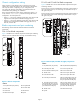
Figure 3 Removing three different filler panel types
Callouts
1. Filler panel with handle
5. Ejectors (2)
2. Captive screws (2)
6. Pull tabs (2)
3. Handle 7. Filler panel with pull tabs
4. Fi
ller panel with ejectors
1. To remove a filler p anel with a handle:
a. Unscrew the two captive screws securing the filler panel.
b. Grasp the handle in the middle of the filler panel and remove.
2. To remove a filler panel with ejectors:
a. Push in the yellow tab on each ejector.
b. Lever both ejectors all the way open, and remove the filler
panel from the chassis.
3. To remove a filler panel with pull tabs:
a. Unscrew the top and bot tom captive screws on the filler panel.
b. Pull on the top an
d bottom pulling tabs to slide the filler panel
out of the chassis.
IMPORTANT:
Remove a filler panel only when installing a port blade. Any
slot that is not occupied by a port blade requires a filler panel to
ensure correct cooling of the chassis and protection from dust.
Installing the port blade
The FC4–16 and FC4–32 port blades use the same procedure.
However, the FC4–48 differs slightly in design. Port blade-specific
instructions are called out where applicable, as follows:
CAUTION:
Wear a ground
ed ESD strap when handling the port blade.
The 4/256 SAN Director chassis has a grounding connection
above the power connectors.
1. Locate an appropriate slot. Install port blad es in slots 1 through 4;
and 7 through 10.
NOTE:
For details on supported mixed blade configurations, refer to
the
HP StorageWorks SAN Director installation guide
.
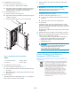
2. Orient the por t blad e so that the ports are at the front of the chassis
and the flat side of the port blade is on the left, see Figure 4.Hold
the por t blade by the edges of the metal pan. Do not use the
ejectors to hold the port blade.
CAUTION:
Make s
ure to gently apply pressure to the port blade, in order
to pro
perly seat the card all the way into the slot. Applying
exces
sive pressure may damage the VHDM connectors on the
Direc
tor’s backplane.
POW
ER SUPPLY 1
200-240 VA
C 12A 5
0-60 Hz
200
-24
0 VA
C 12A 50-60 Hz
POW
ER SUPPLY 1
!
!
POW
ER SUP
PLY 2
!
!
POW
ER SUPPLY 3
!
!
POWER SUPPLY 4
!
!
!
!
FC
4
32
FC4
32
7
6
5
4
3
2
1
0
1
5
1
4
1
3
1
2
1
1
1
0
9
8
5
6
-
0
0
00
5
9
0
-01
R
ev A
!
FC4
16
CP4
L
in
k
1
0
/
1
0
0
M
b
/
s
A
c
t
iv
e
C
P
!
I O I O I RS - 232
CP4
L
in
k
1
0
/
1
0
0
M
b
/
s
A
c
t
iv
e C
P
!
I O I O I RS - 232
7
6
5
4
3
2
1
0
1
5
1
4
1
3
1
2
1
1
1
0
9
8
5
6
-
00
0
0
59
0
-0
1
R
e
v
A
!
FC4
16
1
2
3
4
5
6
7
8
9
1
0
7
6
5
4
3
2
1
0
1
5
1
4
1
3
1
2
1
1
1
0
9
8
5
6
-
0
0
0
0
5
90-0
1
Rev A
!
FC4
16
3
1
2
4
25217a
Figure 4 Installing a FC4–16 or FC4–32 Port Blade
Callouts
1. SAN Director chassis
3. On/Off slider switch
2. FC4-16
4.
Ejector
Page 3