
HP StorageWorks 4Gb SAN Director Port Blade Installation Instructions (A7990-90003, November 2006)


3. If installing th
eFC4–48,gotostep4.
For FC4–16 and FC
4–32 models (see Figure 4).
a. Open th e ejector
s to approximately 45 degrees.
b. Align the flat side of the port blade inside the upper and lower
rail guides in the slot, and slide the port blade into the slot,
with slight pr
essure to the left, until it is firmly seated.
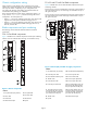
4. For FC4–48 mod
els (see Figure 5):
a. Adjust the ej
ectors to the open position.
b. Align the fla
t side of the port blade inside the upper and lower
rail guides
in the slot.
c. Slide the po
rt blade into the slot, until it is firmly seated.
POWER SUP
PL
Y 1
200
-24
0 VAC
12 A
50-60 Hz
200-24
0 V
AC 12A
50-60
Hz
POWER SUP
PL
Y 1
!
!
POWER
SUP
PLY 2
!
!
POWER S
UP
PL
Y
3
!
!
P
O
W
E
R
SU
PP
L
Y
4
!
!
!
!
FC
4
32
FC
4
32
7
6
5
4
3
2
1
0
1
5
1
4
1
3
1
2
1
1
1
0
9
8
5
6-0
0
00
590
-
0
1
R
ev
A
!
FC
4
16
CP4
Lin
k
10/
100 M b/
s
Active CP
!
I O I O I RS - 232
CP4
Lin
k
10/
100 M b/
s
Active CP
!
I O I O I RS - 232
7
6
5
4
3
2
1
0
1
5
1
4
1
3
1
2
1
1
1
0
9
8
5
6
-00
0
0
59
0-
01
R
e
v
A
!
FC
4
16
1
2
3
4
5
6
7
8
9
1
0
2
4
0
2
5
1
2
6
2
2
7
3
2
8
4
2
9
5
3
0
6
3
1
7
3
2
8
3
3
9
3
4
1
0
3
5
1
1
3
6
1
2
3
7
1
3
3
8
1
4
3
9
1
5
4
0
1
6
4
1
1
7
4
2
1
8
4
3
1
9
4
4
2
0
4
5
2
1
4
6
2
2
4
7
2
3
!
1
25223a
2
3
4
Figur
e 5 Installing an FC4–48 Port Bl ade
Callouts
1. SA
N Director chassis
3. Up
per ejector
2. FC4–48
4. Lower ejector
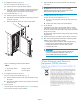
5. If i
nstalling th e FC4 –48, go to step 6.
For
FC4–16 and FC4–32 models (see Figure 4).
a. Pus
h the handles toward the center of the port blade, closing
th
eejectors.
b. Ve
rify that the handle’s levering action properly seats the port
bl
ade in the slot.
6
.
F
or the FC4–48:
A
djust the ejectors to the closed position (see Figure 5) by pulling
them away from the center of the port blade.
7. Tighten the thum
b screw inside each handle using the Phillips
screw driver .
IMPORTANT:
Theupperandlowerthumbscrewsmustbecompletely
tightened, and the upper and lower ejectors must be in the
closed position for the FC4–48 to power on.
8. If installing the FC4–48, go to step 9.
For FC4–16 and FC4–32 models (see Figure 4):
a. To power on the port blade, move up the slider switch in the
top ejector.
b. Verify that the slider switch covers the thumbscrew.
9. For the FC4–48:
Verify that the power LED on the port blade displays a steady
green light (it might require a few seconds to turn on). If it does
not turn on
, ensure that the port blade is firmly seated and that the
thumb scr
ews are tight.
The LED pa
tterns might temporarily change during POST and other
diagnost
ic tests.
10. Install
SFP transceivers and cables in the port blade, as required.
11. Refer to
the HP StorageWorks SAN Director installation guide for
different ways to manage cables, including:
• Routing directly down, through the cable management tray,
instea
d of across adjacent blades to keep LEDs visible.
•Insta
lling cable channels on the sides of the cabinet
•Insta
lling patch panels
IMPORTANT:
Disassembling any part of the port blades voids the part
warranty and regulatory certifications. There are no
user-serviceable parts inside the port blade.
Waste Electrical and Electronic
Equipment (WEEE) directive
Page 4