
- Hewlett-Packard S-Parameter Test Set Operating and Service Manual


HP 8517B S-Parameter Test Set Manual
6-11
HP 8517B Test Set Replacement Procedures
Assembly Replacement Procedures
Bias Tees Replacement A7 and A9 Bias Tees
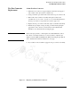
1. See Figure 6-2 for component locations.
2. Remove the two semi-rigid cables attached to the bias tee to be replaced.
3. De-solder the wires attached to the bias tee.
4. Remove the two screws that secure the bias tee to the bias-tee bracket.
5. Remove the bias tee.
NOTE
This procedure does not apply to Option 002 or Option 002 “plus” 007.
Test Port Coupler
Replacement
A6 and A8 Test Port Couplers
1. See Figure 6-2 for component locations.
2. Remove the front panel assembly as described in the procedure “A1
Front Panel and Interface Board Assembly”.
3. Remove the test port connector nut with a 1-inch wrench.
4. Remove the test port washer.
5. Remove the coupler from the front panel.
Test Port Attenuator
Replacement
A16 or A17 Port Attenuators
NOTE
This procedure does not apply to Option 002 or Option 002 “plus” 007.
1. See Figure 6-2 for component locations.
2. Remove the two semi-rigid cables attached to the attenuator.
3. Unplug the ribbon cable from the attenuator.
4. Remove the two screws that secure the attenuator bracket to the
amplifier bracket.
5. Remove the attenuator/attenuator bracket from the instrument.
6. Remove the two screws that secure the attenuator to the attenuator
bracket.