HP BladeSystem c7000 Carrier-Grade Enclosure Maintenance and Service Guide Abstract This document contains specific information that is intended for users of this HP product.
© Copyright 2007 – 2013 Hewlett-Packard Development Company, L.P. The information contained herein is subject to change without notice. The only warranties for HP products and services are set forth in the express warranty statements accompanying such products and services. Nothing herein should be construed as constituting an additional warranty. HP shall not be liable for technical or editorial errors or omissions contained herein.
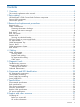
Contents 1 Overview..................................................................................................5 This manual supplements other manuals......................................................................................5 2 Parts catalog..............................................................................................6 HP BladeSystem c7000 Carrier-Grade Enclosure components.........................................................6 Seismic Rack components...................
Subscription service............................................................................................................27 Documentation feedback....................................................................................................27 Installing HP Insight Remote Support Software............................................................................28 Related information.................................................................................................................
1 Overview This manual supplements other manuals This manual is not intended as a standalone document. This manual is written as a supplement to manuals that describe other similar products, and you will need some of the documentation for these products to complete the tasks described in this manual. The HP Carrier-Grade BladeSystems are closely related to the commercial HP BladeSystem products. For a complete list of related documents, see “Related information” (page 28).
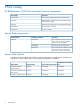
2 Parts catalog HP BladeSystem c7000 Carrier-Grade Enclosure components Part Number Description 544660-002 Power supply - Rated at 2250 Watts, -48VDC output AH332A HP BladeSystem c7000 Enclosure 2250 Watts Hot Plug -48V DC Power Supply AH333A HP Blade System AMC Carrier Grade Expansion Blade 544682-001 DC input power - Terminal 544661-002 DC power module Seismic Rack components Product Number Assembly Part Number Description AH343A 544643-001 Seismic Rack Set includes one 36U 1M seismic rac
3 Removal and replacement procedures NOTE: The HP BladeSystem c7000 Carrier-Grade Enclosure is similar to the HP BladeSystem c7000.
Warning and caution messages WARNING! To reduce the risk of personal injury or damage to equipment, heed all warnings and cautions throughout the installation instructions. WARNING! To reduce the risk of personal injury or damage to the equipment, you must adequately support enclosures during installation and removal. WARNING! Before installing an enclosure in the rack, be sure that all hot-plug power supplies, server blades, and interconnects are removed from the enclosure.
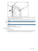
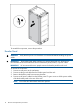
5. 6. Pull down on the spring-loaded handles on the hinge assembly at the top of the door until the small pin securing the door to the hinge retracts. Move the top of the door away from the rack until the spring-loaded pin is free of the hinge assembly. CAUTION: Do not move the top of the door farther away from the rack than necessary. Moving the top of the door too much from the rack can bend the pin holding the bottom of the door. 7.
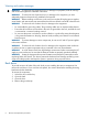
To reinstall the component, reverse the procedure. Breaker Panel WARNING! cables. Verify that the power circuit breakers are switched off before handling the power IMPORTANT: The breaker panel safety marking is for trained personnel only. HP does not recommend that untrained individuals service the breaker panel, breaker, or power cables. IMPORTANT: HP recommends that two people remove the breaker panel from the rack. To remove the component: 1. Disconnect site power at the site battery. 2.
5. Remove the screws, and slide the breaker panel out through the front of the rack. To reinstall the component, reverse the procedure. Servicing an individual breaker The individual breakers can be serviced with telecom equipment connected to the rear output terminals. CAUTION: For safety purposes, a breaker must be switched off when removed or inserted. 1. 2. Switch the breaker off. Remove the breaker. a. Unscrew the two breaker screws with a Phillips screwdriver. b.
3. Remove the power supply or power supply blank. DC Input Module WARNING! cables. Ensure that the power circuit breakers are turned off before handling the power CAUTION: To prevent damage to the input module, all power connections and both ground cables must be disconnected from the input module before it can be removed. NOTE: Before removing the DC input module, you must power down the server blades and enclosure.
6. Remove the DC input module. To replace the component, reverse the removal procedure. Cable Management Tray Remove the screws, and slide the cable management tray out of the mounting rails. NOTE: If you have any difficulty sliding the cable management tray out of the mounting rails, loosen the screws that hold the rail brackets and then slide the tray out. To reinstall the component, reverse the procedure. Seismic Brace CAUTION: The seismic top brace weighs 35 lbs, use caution when moving it.
2. 3. Remove the four middle screws in the rear brace. From the front, remove the screws from the top brace, and then slide the top brace from the rack. 4. Remove the screws, remove the two rear brackets, and remove and the rear brace. 5. Remove the cage nuts from all four mounting rails. To replace the component, reverse the removal procedure. Cable Management System To remove the component: 1. Loosen the screws, and remove the cable guide from each rear rail.
2. Remove the cage nuts from the rear mounting holes. To replace the component, reverse the removal procedure. Rack Mount NOTE: The U locations are noted in the following procedure for enclosures installed in the lower portion of the rack. When installing multiple enclosures into the rack, use the U locations in parentheses for the top enclosure. To remove the components: 1. Remove the cage nuts from the middle hole of U9 (U20) and top hole of U4 (U15) in the front mounting rails. 2.
4 Cabling Cable management CAUTION: Gigabit Ethernet ports (intrabuilding ports) of the HP BladeSystem c7000 Carrier-Grade system require the use of shielded Cat5e cables grounded at both ends. The intrabuilding ports of the equipment are suitable for connection only to intrabuilding, unexposed wiring, or cabling. Do not connect the intrabuilding ports of the equipment metallically to interfaces that connect to the outside plant or its wiring.
Item Description 5 U14.5 6 U10 Route signal and power cables through the top of the rack, directly above the signal and power routing areas. Route left cables out of the top left of the rack. Route right cables out of the top right of the rack. To prevent strain, use a hook-and-loop strap and secure existing signal cables to the highest location available on the rack ground rail. Make sure to keep cables clear of any ground screws.
3. Secure each guide to the cable management system frame. You can also use hook-and-loop straps to fasten cables to the rack.
Breaker Panel cabling There are two cable options available: • BLc2.0 cable—Connects the upper breaker panel (U35-U36) to the lower enclosure DC input module (U1-U10). • BLc1.3 cable—Connects the lower breaker panel to the upper enclosure DC input module. Each cable option contains six pairs of red and black cables. The ends of each cable are different. The 90-degree cable end connects to the breaker panel. The 45-degree cable end connects to the enclosure DC input module.
DC Input Module cabling Cable repair If there is fiber cable that is not easily removed from the system: 20 • Disconnect both of the cable ends and cut cable several inches away from each connector • Route new cable over the top of the old fiber cable, observing all routing rules in “Cabling” (page 16) and the module specific documentation.
5 Diagnostic tools Troubleshooting resources NOTE: For common troubleshooting procedures, the term "server" is used to mean servers and server blades. The HP ProLiant Servers Troubleshooting Guide provides simple procedures for resolving common problems as well as a comprehensive course of action for fault isolation and identification, error message interpretation, issue resolution, and software maintenance.
Onboard Administrator If an error occurs, the Onboard Administrator displays an error message on the Insight Display. In addition, the Onboard Administrator also displays error messages in email alerts and SNMP traps, if this feature is configured. For more information, see the HP BladeSystem Onboard Administrator User Guide.
6 Component and LED identification DC Input Module components 1 2 3 Terminal block Case screw (4x) Captive screw (3x) 4 5 6 Ground stud (4x) -48V (Power) RTN (Return) Terminal Block numbering DC Input Module components 23
Power Supply Bay numbering Power Supply LEDs Power LED 1 (green) Fault LED 2 (amber) Condition On Off Power supply DC output on and OK DC present/standby output on 24 Off On Power supply failure Off Off No DC power to power supply Component and LED identification
7 Specifications Environmental specifications Specification Value Temperature range 1 Operating 5°C to 40°C (41°F to 104°F) Non operating -30°C to 60°C (-22°F to 140°F) Short-term -5°C to 50°C (23°F to 122°F) Wet bulb temperature Operating 28ºC (82.4ºF) Non operating 38.7ºC (101.7ºF) Relative humidity (noncondensing) 2 Operating 20% to 80% Non-operating 5% to 95% 1 2 All temperature ratings shown are for sea level. An altitude derating of 1°C per 304.8 m (1.
Unpacking area: When moving the cabinet off the shipping pallet, you need approximately 9 feet (2.74 meters) on one side of the cabinet to allow you to slide the pallet out from under the cabinet after the cabinet has been raised on the casters. Enclosure specifications Specification Value Height 759.00 mm (29.88 in) Depth 1013.00 mm (39.88 in) Width 607.00 mm (23.88 in) Maximum enclosure weight1 Unboxed 204.0 kg (450.0 lb) Shipping 223.6 kg (493.
8 Support and other resources Contacting HP Before you contact HP Be sure to have the following information available before you call contact HP: • Technical support registration number (if applicable) • Product serial number • Product model name and number • Product identification number • Applicable error message • Add-on boards or hardware • Third-party hardware or software • Operating system type and revision level HP contact information For the name of the nearest HP authorized reseller
Installing HP Insight Remote Support Software HP strongly recommends that you install HP Insight Remote Support software to complete the installation or upgrade of your product and to enable improved delivery of your HP Warranty, HP Care Pack Service or HP contractual support agreement.
NOTE: A note contains additional information to emphasize or supplement important points of the main text.
A Alternate-Sized site cables This appendix provides information for customers who plan to use alternate-sized site power input cables and lugs to connect site power. The alternate-sized cables and lugs must be provided by the customer or the installation provider for the customer. HP does not provide these items to the customer. IMPORTANT: The power cables should be assembled by a certified electrician only.
To ensure the alternate sized site power input cables you plan to use meet the ampacity requirements for a NEBS 40°C environment: • Use Table 310.16 or Table 310.18 (see “Required documentation” (page 30)) to determine the correct cable size, based on the type and grade of cable that you plan to use. • Apply the correction factor from Table 310.16 or Table 310.
B Acronyms and abbreviations CSA ESD FCC IEC NEMA NFPA NIC NEBS PDU SAS UID UTP 32 Canadian Standards Association electrostatic discharge Federal Communications Commission International Electrotechnical Commission National Electrical Manufacturers Association National Fire Protection Association network interface controller Network Equipment–Building system power distribution unit serial attached SCSI unit identification unshielded twisted-pair Acronyms and abbreviations
Index assembly part numbers, 6 troubleshooting tips resources, 21 C W cable management system, 14 cables alternate sizes, 30 grounding, 30 power, 30 components, 6 warnings, 8 warnings and cautions, 21 websites product manuals, 28 A D diagnostics, 21 document related documentation, 28 documentation HP website, 28 E electrostatic discharge, 7 enclosure cabling, 16 I input module, 12 O Onboard administrator, 22 P parts list, 6 power supply, 11 LEDs, 24 power supply blank, 11 R rack doors, 8 rack mo