
FW V06.XX/HAFM SW V08.02.00 HP StorageWorks SAN High Availability Planning Guide (AA-RS2DD-TE, July 2004)


Table Of Contents
- SAN HA Planning Guide
- Contents
- About this Guide
- Introduction to HP Fibre Channel Products
- Product Management
- Planning Considerations for Fibre Channel Topologies
- Fibre Channel Topologies
- Planning for Point-to-Point Connectivity
- Characteristics of Arbitrated Loop Operation
- Planning for Private Arbitrated Loop Connectivity
- Planning for Fabric-Attached Loop Connectivity
- Planning for Multi-Switch Fabric Support
- Fabric Topologies
- Planning a Fibre Channel Fabric Topology
- Fabric Topology Design Considerations
- FICON Cascading
- Physical Planning Considerations
- Port Connectivity and Fiber-Optic Cabling
- HAFM Appliance, LAN, and Remote Access Support
- Inband Management Access (Optional)
- Security Provisions
- Optional Features
- Configuration Planning Tasks
- Task 1: Prepare a Site Plan
- Task 2: Plan Fibre Channel Cable Routing
- Task 3: Consider Interoperability with Fabric Elements and End Devices
- Task 4: Plan Console Management Support
- Task 5: Plan Ethernet Access
- Task 6: Plan Network Addresses
- Task 7: Plan SNMP Support (Optional)
- Task 8: Plan E-Mail Notification (Optional)
- Task 9: Establish Product and HAFM Appliance Security Measures
- Task 10: Plan Phone Connections
- Task 11: Diagram the Planned Configuration
- Task 12: Assign Port Names and Nicknames
- Task 13: Complete the Planning Worksheet
- Task 14: Plan AC Power
- Task 15: Plan a Multi-Switch Fabric (Optional)
- Task 16: Plan Zone Sets for Multiple Products (Optional)
- Index
Planning Considerations for Fibre Channel Topologies
129SAN High Availability Planning Guide
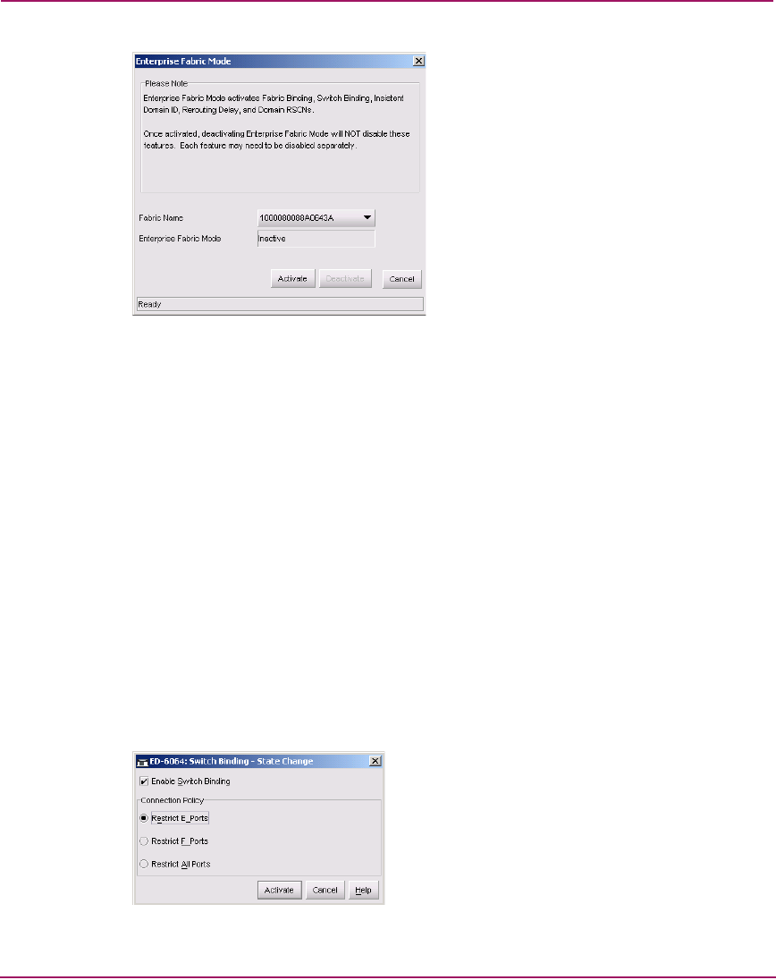
Figure 52: Enterprise Fabric Mode Dialog Box
b. Select the fabric to be configured from the Fabric Name drop-down list.
The selected fabric’s status displays in the Enterprise Fabric Mode field.
c. Click Activate to close the dialog box and enable Enterprise Fabric
Mode for the selected fabric.
7. Verify FICON devices are still logged in — Maximize the Element
Manager application. Inspect the Node List View (Figure 51) and verify
FICON devices (channels and control units inspected in step 5) are still
logged in to each director or switch.
8. Change switch binding enforcement if required — If the SAN
environment is volatile (characterized by a high volume of optical cable
connects, disconnects, and movement), change switch binding enforcement to
restrict E_Ports only.
a. In the Element Manager application, click the Hardware tab. In the
Hardware View, select Switch Binding, and then select Change State
from the Configure menu. The Switch Binding - State Change dialog
box displays (Figure 53).
Figure 53: Switch Binding - State Change Dialog Box