
FW 07.00.00/HAFM SW 08.06.00 McDATA SANpilot User Manual (620-000160-230, April 2005)


3
MAP 0000: Start MAP
3-11
Diagnostics
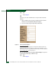
The grey square indicates the EFC Server cannot communicate with
the switch because:
• The switch-to-EFC Server Ethernet link failed.
• Ac power distribution in the switch failed.
• The control processor (CTP) card failed.
Does a grey square appear at the alert panel and as the background
to the icon representing the switch reporting the problem?
YES NO
↓ Go to step 10.
8
At the switch reporting the problem, ensure the power switch is set to
the Power On (1) position. Inspect the switch for indications of being
powered on, such as:
• At the front panel, an illuminated PWR or ERR indicator.
• Green LEDs illuminated on the power supplies.
• Audio emanations and airflow from fans.
Does the switch appear powered on?
YES NO
↓ A power distribution problem is indicated. Go to step 23 to
obtain event codes. If no event codes are found, go to MAP
0100: Power Distribution Analysis on page 3-28.
9
Either a switch-to-EFC Server Ethernet link failure or CTP card failure
is indicated. Go to step 23 to obtain event codes. If no event codes
are found:
a. Fault isolate the least severe failure indicated (Ethernet link
problem). Go to MAP 0400: Loss of Console Communication on
page 3-46.
b. If MAP 400 does not isolate the problem, fault isolate the CTP
card problem. Go to MAP 0200: POST, Reset, or IPL Failure
Analysis on page 3-35.