HP HSR6800 Routers IRF Configuration Guide Part number: 5998-4487 Software version: HSR6800-CMW520-R3303P05 Document version: 6PW105-20140507
Legal and notice information © Copyright 2014 Hewlett-Packard Development Company, L.P. No part of this documentation may be reproduced or transmitted in any form or by any means without prior written consent of Hewlett-Packard Development Company, L.P. The information contained herein is subject to change without notice.
Contents IRF overview ································································································································································· 1 Hardware compatibility ···················································································································································· 1 Chassis compatibility ··································································································································
Configuring a member device description ········································································································· 21 Configuring IRF bridge MAC persistence ··········································································································· 21 Enabling software auto-update for system software image synchronization ·················································· 22 Setting the IRF link down report delay ················································
IRF overview The HP Intelligent Resilient Framework (IRF) technology creates a large IRF fabric from multiple devices to provide data center class availability and scalability. IRF virtualization technology offers processing power, interaction, unified management, and uninterrupted maintenance of multiple devices. This book describes IRF concepts and guides you through the IRF setup procedure. Hardware compatibility This section describes the IRF and hardware compatibility.
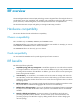
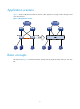
Application scenario Figure 1 shows an IRF fabric that has two devices, which appears as a single node to the upper and lower layer devices. Figure 1 IRF application scenario Basic concepts This section uses Figure 2 to describe the basic concepts that you might encounter when you work with IRF.
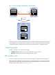
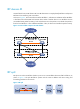
Figure 2 Two-chassis IRF fabric implementation schematic diagram Device A (MemberID=1) Device B (MemberID=2) Active MPU Active MPU Standby MPU Standby MPU IRF-port 2 IRF-port 1 IRF link Service XGE1/3/0/1 interface Physical IRF port XGE2/3/0/1 Service Physical IRF interface port An IRF fabric is formed.
IRF member ID An IRF fabric uses member IDs to uniquely identify and manage its members. This member ID information is included as the first part of interface numbers and file paths to uniquely identify interfaces and files in an IRF fabric. For example, after you assign a device with member ID 2 to an IRF fabric, the name of interface GigabitEthernet 3/0/1 changes to GigabitEthernet 2/3/0/1, and the file path slot1#cfa0:/test.cfg changes to chassis2#slot1#cfa0:/test.cfg.
IRF domain ID One IRF fabric forms one IRF domain. IRF uses IRF domain IDs to uniquely identify IRF fabrics and prevent IRF fabrics from interfering with one another. As shown in Figure 3, Device A and Device B form IRF fabric 1, and Router A and Router B form IRF fabric 2. The fabrics have LACP MAD links between them.
IRF merge IRF merge occurs when two split IRF fabrics reunite or when you configure and connect two independent IRF fabrics to be one, as shown in Figure 5. Figure 5 IRF merge IRF 1 IRF IRF 2 + Device A XGE1/3/0/1 = Device B XGE2/3/0/1 IRF link Device A Device B Member priority Member priority determines the possibility of a member device to be elected the master. A member with higher priority is more likely to be elected the master. The default member priority is 1.
IRF multi-active detection An IRF link failure causes an IRF fabric to split in two IRF fabrics operating with the same Layer 3 configurations, including the same IP address. To avoid IP address collision and network problems, IRF uses multi-active detection (MAD) mechanisms to detect the presence of multiple identical IRF fabrics, handle collisions, and recover from faults. Multi-active handling procedure The multi-active handling procedure includes detection, collision handling and failure recovery.
• If the extended LACPDUs convey the same domain ID but different active IDs, a split has occurred. To handle this situation, LACP MAD sets the IRF fabric with higher active ID in Recovery state, and shuts down all its physical ports except for the console ports, IRF ports, and any ports you have specified with the mad exclude interface command. The IRF fabric with lower active ID is still in Detect state and forwards traffic.
• When the IRF fabric splits, the IP addresses of the masters in the split IRF fabrics take effect, and the two masters can establish a BFD session. If you use the display bfd session command, the state of the BFD session between the two devices is Up. Figure 7 BFD MAD application scenario Customer premises network Device Link aggregation IRF BFD MAD link VLAN 2 192.168.1.2/24 VLAN 2 192.168.1.
Figure 8 ARP MAD application scenario Customer premises network STP Domain To avoid loops, all devices in the domain must run the spanning tree feature. Device IRF IRF link Subordinate Master Internet Common traffic path Extended gratuitous ARP traffic path Each IRF member compares the domain ID and the active ID in incoming extended gratuitous ARP packets with its domain ID and active ID: • If the domain IDs are different, the extended gratuitous ARP packet is from a different IRF fabric.
Configuring IRF To ensure a successful IRF setup, read the configuration restrictions and guidelines carefully before you connect and set up an IRF fabric. General restrictions and configuration guidelines Software requirements All IRF member devices must run the same system software image version. MPU and IRF physical port restrictions • You can only use the 10-GE fiber ports on the SAP-4EXP cards for IRF connection. • Make sure every IRF member has at least one MPU.
• Assign each member a unique IRF member ID to make sure they can merge. You must reboot the members to validate the IRF member ID settings. • Assign the highest member priority to the device you want to use as the master. • Save any configuration you have made to the startup configuration file before rebooting the IRF member devices. Setup and configuration task list HP recommends the following IRF fabric setup and configuration procedure: Task Remarks Planning the IRF fabric setup 1. Required.
Planning the IRF fabric setup Consider the following items when you plan an IRF fabric: • Hardware compatibility and restrictions • IRF fabric size • Master device • IRF physical ports • Member ID and priority assignment scheme • Fabric topology and cabling scheme For more information about hardware and cabling, see the installation guide for the device. Preconfiguring IRF member devices in standalone mode Perform the tasks in this section on every IRF member device.
Step Command Remarks 1. Enter system view. system-view N/A 2. Specify a priority for the device. irf priority priority The default IRF member priority is 1. Binding physical ports to IRF ports To establish an IRF connection between two devices, you must bind at least one physical port to IRF-port 1 on one device and to IRF-port 2 on the other. For link redundancy and load sharing, bind multiple physical ports to one IRF port. Make sure the IRF physical ports are operating as Layer 2 interfaces.
Connecting physical IRF ports When you connect two neighboring IRF members, connect the physical ports of IRF-port 1 on one member to the physical ports of IRF-port 2 on the other, as shown in Figure 9. Follow these guidelines when selecting transceiver modules and cables: • Use SFP+ transceiver modules and fibers for long-distance connection.
Setting the operating mode to IRF mode By default, the device is operating in standalone mode. To assign the device to an IRF fabric, you must change its operating mode to IRF mode. Before changing to IRF mode, use the display irf configuration command to verify that a member ID has been assigned to the device. If the MemberID field displays two hyphens (--), first assign a member ID to the device. To set the operating mode of a device to IRF mode: Step Command Remarks 1. Enter system view.
Accessing a standby MPU in the IRF fabric You can log in to the CLI of a standby MPU for maintenance or debugging. When you change from the global active MPU's CLI to the standby MPU's CLI, you are placed in user view and the command prompt changes to , for example, .
Figure 11 A network that comprises two IRF domains To assign a domain ID to an IRF fabric: Step Command Remarks 1. Enter system view. system-view N/A 2. Assign a domain ID to the IRF fabric. irf domain domain-id By default, the domain ID of an IRF fabric is 0. Changing the member ID of a device CAUTION: In IRF mode, an IRF member ID change can invalidate member ID-related settings and cause data loss. Be sure you fully understand its impact on your live network.
Step 3. 4. Save the running configuration. Reboot the member device. Command Remarks save [ safely ] N/A reboot chassis chassis-number The chassis-number must be the same as the member-id specified in the irf member member-id renumber new-member-id command. Changing the priority of a member device You can change the priority of a member device so it can be elected as the master at the next master election.
Step Command Remarks • Enter interface range view: { 2. Enter Ethernet interface view or interface range view. { Method 1: interface range { interface-type interface-number [ to interface-type interface-number ] } &<1-5> Method 2: interface range name name [ interface { interface-type interface-number [ to interface-type interface-number ] } &<1-5> ] To shut down a range of physical IRF ports, enter interface range view. To shut down one physical IRF port, enter its interface view.
This function can work only when it is enabled on both IRF fabrics that are merging. The IRF auto merge function does not take effect on the IRF fabric merge caused by binding a physical port to an IRF port in IRF mode. You must manually reboot the devices that have been defeated in the master selection to complete the merge. To enable IRF auto merge: Step Command Remarks 1. Enter system view. system-view N/A 2. Enable IRF auto merge. irf auto-merge enable By default, this function is disabled.
If two IRF fabrics have the same bridge MAC address, they cannot merge. To configure the IRF bridge MAC persistence setting: Step Enter system view. 1. Command Remarks system-view N/A • Retain the bridge MAC address even if the master has changed: irf mac-address persistent always Configure IRF bridge MAC persistence. 2.
Setting the IRF link down report delay You can avoid link flapping causing frequent IRF splits and merges during a short time by configuring the IRF ports to delay reporting link down events. An IRF port thus works as follows: • When the IRF link changes from up to down, the port does not immediately report the change to the IRF fabric. If the IRF link state is still down when the delay time is reached, the port reports the change to the IRF fabric.
MAD mechanism Advantages Disadvantages Application scenario • No special requirements for network scenarios. • Requires MAD dedicated physical ports and Layer 3 interfaces, which cannot be used for transmitting user traffic. • Detection speed is fast. • No intermediate device is BFD MAD device is used, this mechanism is only suitable for IRF fabrics that have a small number of members that are geographically close to one another. • If no intermediate device required.
Step Command Remarks Configure the aggregation group to operate in dynamic aggregation mode. link-aggregation mode dynamic By default, an aggregation group operates in static aggregation mode. 5. Enable LACP MAD. mad enable By default, LACP MAD is disabled. 6. Return to system view. quit N/A 4. Perform this step also on the intermediate device. • Enter interface range view: { 7. Enter Ethernet interface view or interface range view.
Category Restrictions and guidelines • Do not enable BFD MAD on a VLAN interface that has been assigned an IP address. The VLAN interface becomes unreachable even if you disable BFD MAD. To recover the connectivity of the VLAN interface, use the shutdown and undo shutdown commands or reset ARP. IP address requirements • To avoid problems, only use the mad ip address command to configure IP addresses on the BFD MAD-enabled VLAN interface.
Step Command Configure a MAD IP address for a member on the VLAN interface. 9. Remarks mad ip address ip-address { mask | mask-length } member member-id By default, no MAD IP address is configured on any VLAN interface. Repeat this step to assign a MAD IP address to each member device on the VLAN interface. Configuring ARP MAD When you configure ARP MAD, follow these guidelines: • If an intermediate device is used, you can use common data links as ARP MAD links.
Step Command Remarks • Assign the port to the VLAN as an access port: port access vlan vlan-id Assign the port or the range of ports to the ARP MAD VLAN. 6. • Assign the port to the VLAN as a trunk port: port trunk permit vlan vlan-id Choose one command depending on the port type. ARP MAD has no requirement for the link type. • Assign the port to the VLAN as a The default link type of a port is access. hybrid port: port hybrid vlan vlan-id { tagged | untagged } 7. Return to system view.
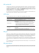
Figure 12 Recovering the IRF fabric IP network IP network IRF 2 (Inactive) IRF 1 (Active) Network ports that have been shut down IRF IRF link recovered Network ports that have been shut down IP network IP network If the active IRF fabric has failed, for example, because of device or link failures, before the IRF link is recovered (see Figure 13), use the mad restore command on the inactive IRF fabric to change its MAD state to Detect and bring up all physical ports that was shut down by MAD.
Displaying and maintaining an IRF fabric Task Command Remarks Display information about all IRF members. display irf [ | { begin | exclude | include } regular-expression ] Available in any view. Display the IRF fabric topology. display irf topology [ | { begin | exclude | include } regular-expression ] Available in any view. Display basic IRF settings. display irf configuration [ | { begin | exclude | include } regular-expression ] Available in any view. Display MAD configuration.
Configuration procedure IMPORTANT: For two neighboring IRF members, IRF links must be bound to IRF-port 1 on one member and to IRF-port 2 on the other. 1. Configure Router A: # Assign member ID 1 to Router A and bind Ten-GigabitEthernet 3/0/1 to IRF-port 2. system-view [Sysname] irf member 1 Info: Member ID change will take effect after the member reboots and operates in IRF mode.
[Sysname-irf-port1] port group interface ten-gigabitethernet 3/0/1 [Sysname-irf-port1] quit [Sysname] interface ten-gigabitethernet 3/0/1 [Sysname-Ten-GigabitEthernet3/0/1] undo shutdown [Sysname-Ten-GigabitEthernet3/0/1] quit # Save the configuration. [Sysname] quit save # Connect the two devices as shown in Figure 14. # Log in to Router B. (Details not shown.) # Enable IRF mode. system-view [Sysname] chassis convert mode irf The device will switch to IRF mode and reboot.
CAUTION: If the intermediate device is also in an IRF fabric, assign the two IRF fabrics different domain IDs for correct split detection. # Create a dynamic aggregate interface. system-view [Sysname] interface bridge-aggregation 2 [Sysname-Bridge-Aggregation2] link-aggregation mode dynamic [Sysname-Bridge-Aggregation2] quit # Assign GigabitEthernet 4/0/1 and GigabitEthernet 4/0/2 to the aggregate interface.
Configuration procedure 1. Configure Router A: # Assign member ID 1 to Router A and bind Ten-GigabitEthernet 3/0/1 to IRF-port 2. system-view [Sysname] irf member 1 Info: Member ID change will take effect after the member reboots and operates in IRF mode.
[Sysname-irf-port1] quit [Sysname] interface ten-gigabitethernet 3/0/1 [Sysname-Ten-GigabitEthernet3/0/1] undo shutdown [Sysname-Ten-GigabitEthernet3/0/1] quit # Save the configuration. [Sysname] quit save # Connect the two devices as shown in Figure 15. # Log in to Router B. (Details not shown.) # Enable IRF mode. system-view [Sysname] chassis convert mode irf The device will switch to IRF mode and reboot.
ARP MAD-enabled IRF configuration example Network requirements Set up a two-chassis IRF fabric at the distribution layer of the enterprise network in Figure 16. Configure ARP MAD for the IRF fabric and use Router C as an intermediate device. Router C can come from any vendor. To prevent loops, enable the spanning tree feature between the IRF fabric and Router C. Figure 16 Network diagram Configuration procedure 1.
Saving the converted configuration file to the main board succeeded. Slot 1: Saving the converted configuration file succeeded. Now rebooting, please wait... Router A reboots to form a one-chassis IRF fabric. 2. Configure Router B: # Assign member ID 2 to Router B and bind Ten-GigabitEthernet 3/0/1 to IRF-port 1. system-view [Sysname] irf member 2 Info: Member ID change will take effect after the member reboots and operates in IRF mode.
[Sysname] interface vlan-interface 3 [Sysname-Vlan-interface3] mad arp enable You need to assign a domain ID (range: 0-4294967295) [Current domain is: 1]: The assigned domain ID is: 1 [Sysname-Vlan-interface3] ip address 192.168.2.1 24 4. Configure Router C as the intermediate device: CAUTION: If the intermediate device is also in an IRF fabric, assign the two IRF fabrics different domain IDs for correct split detection. # Enable the spanning tree feature globally on Router C.
1 1 Slave 1 000f-e200-0501 RouterA 2 0 Slave 1 000f-e200-060a RouterB 2 1 Slave 1 000f-e200-050b RouterB -------------------------------------------------- * indicates the device is the master. + indicates the device through which the user logs in. The Bridge MAC of the IRF is: 000f-e26a-58ed Auto upgrade : no Mac persistent : always Domain ID : 0 The output shows that Router A is the master. 2. Examine the configuration for VLAN interfaces.
The device will switch to stand-alone mode and reboot. You are recommended to save the current running configuration and specify the configuration file for the next startup. Continue? [Y/N]:y Do you want to convert the content of the next startup configuration file flash:/vrpcfg.cfg to make it available in stand-alone mode? [Y/N]:y Please wait............. Saving the converted configuration file to main board succeeded. Chassis 2 Slot 1: Saving the converted configuration file succeeded.
Support and other resources Contacting HP For worldwide technical support information, see the HP support website: http://www.hp.
Conventions This section describes the conventions used in this documentation set. Command conventions Convention Description Boldface Bold text represents commands and keywords that you enter literally as shown. Italic Italic text represents arguments that you replace with actual values. [] Square brackets enclose syntax choices (keywords or arguments) that are optional. { x | y | ... } Braces enclose a set of required syntax choices separated by vertical bars, from which you select one.
Network topology icons Represents a generic network device, such as a router, switch, or firewall. Represents a routing-capable device, such as a router or Layer 3 switch. Represents a generic switch, such as a Layer 2 or Layer 3 switch, or a router that supports Layer 2 forwarding and other Layer 2 features. Represents an access controller, a unified wired-WLAN module, or the switching engine on a unified wired-WLAN switch. Represents an access point.
Index ABCDGHIMPRS A Hardware compatibility,1 Accessing the IRF fabric,16 I Application scenario,2 IRF benefits,1 B IRF multi-active detection,7 Basic concepts,2 M C Master election,6 Configuration examples,30 P Configuring IRF member devices in IRF mode,17 Planning the IRF fabric setup,13 Connecting physical IRF ports,15 Contacting HP,41 Preconfiguring IRF member devices in standalone mode,13 Conventions,42 R D Related information,41 Displaying and maintaining an IRF fabric,30 S G S