
R3303-HP HSR6800 Routers IRF Configuration Guide

3
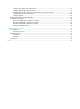
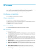
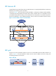
Figure 2 Two-chassis IRF fabric implementation schematic diagram
In this figure, Device A and Device B form a two-chassis IRF fabric that has four MPUs (one active and
three standbys) and two times the number of interface cards that a single device provides. The IRF fabric
manages the physical and software resources of Device A and Device B in a centralized manner.
Operating mode
The device operates in one of the following modes:
• Standalone mode—The device cannot form an IRF fabric with other devices.
• IRF mode—The device can form an IRF fabric with other devices.
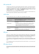
IRF member roles
IRF uses two member roles: master and slave (called "subordinate" throughout the documentation).
When devices form an IRF fabric, they elect a master to manage the IRF fabric, and all other devices back
up the master. When the master device fails, the other devices automatically elect a new master. For more
information about master election, see "Master election."
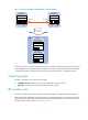
IRF link
An IRF fabric
is formed.
Master
(MemberID=1)
Subordinate
(MemberID=2)
Active MPU
Device A
(MemberID=1)
Device B
(MemberID=2)
XGE1/3/0/1
Physical IRF
port
XGE2/3/0/1
Physical IRF
port
IRF-port 2 IRF-port 1
Service
interface
Service
interface
IRF
Standby MPU
Active MPU
Standby MPU
IRF’s Active MPU
IRF’s standby MPU
IRF’s standby MPU
IRF’s standby MPU