HP Insight Control Power Management 7.3 User Guide Abstract This document describes the concepts of power management, provides information on managing power in your data center based on real-time user scenarios, lists troubleshooting information, and includes other additional information.
© Copyright 2004, 2014 Hewlett-Packard Development Company, L.P. Legal Notices Confidential computer software. Valid license from HP required for possession, use or copying. Consistent with FAR 12.211 and 12.212, Commercial Computer Software, Computer Software Documentation, and Technical Data for Commercial Items are licensed to the U.S. Government under vendor's standard commercial license. The information contained herein is subject to change without notice.
Contents 1 Introduction...............................................................................................5 2 Key concepts.............................................................................................7 Data centers, racks, and power delivery devices...........................................................................7 Data centers........................................................................................................................7 Racks....................
Task: Task: Task: Task: Task: Task: Task: Task: Generating power topology for BladeSystem enclosures through iPDUs..................................28 Classifying systems by business criticality...........................................................................28 Defining rules to reduce power consumption .....................................................................28 Defining rules for external events......................................................................................
1 Introduction HP Insight Control power management (power management) is a component of HP Insight Control to work on Windows, HP Insight Control for Linux to work on Linux, HP-UX 11i v3 Base Operating Environment to work on HP-UX, OpenVMS Base Operating Environment to work on OpenVMS, and NonStop System Console companion DVD to work on the NonStop J-series operating system.
• Chart inlet air temperature for a single system, a group of systems, a single c-Class enclosure, a group of c-Class enclosures, or a mix of the above systems. View a visualization of 24-hour peak temperatures across a data center floor and within each rack. • Download historical data in CSV format to create customized reports. • View dashboard analysis data, including power savings due to HP Power Regulator technology, for a single system or group of systems.
2 Key concepts Data centers, racks, and power delivery devices Data centers HP Insight Control power management enables you to define the data center physical topology with racks containing systems, enclosures, and devices. A data center is an arbitrary rectangular grid that allows you to specify the placement of racks. You may create data centers to describe a lab floor or a portion of a computer room. This provides a useful grouping to summarize your environment and its power and thermal requirements.
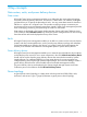
Figure 1 Power topology in a data center Power delivery hierarchy Power is provided through a set of power delivery devices. Insight Control power management represents places that can be monitored in the power delivery points of the hierarchy, such as PDU load segment output, PDU outlet, and so on, or a place where you may want to aggregate and report on power consumption of a set of devices, like servers.
A description of each element follows: • Power Feed—A top-level input of power from the data center facility into the power management-observable power infrastructure. • Breaker Panel—This represents the total group of breakers on a single breaker panel in a PDR. • Branch Circuit—This represents a single output of a PDR circuit breaker or power meter. • Rack PDU—This represents the input power and multiple outputs to load segments.
Power delivery device total capacity calculations If you know the line current (lineCurrent), line voltage (lineVoltage), and type of phase for the device, the total capacity of a power delivery device can be calculated using the following formulas: For 3-phase Wye: phaseVoltage = lineVoltage / sqrt(3) phaseAmps = lineCurrent phaseWatts = phaseVoltage * phaseAmps TotalCapacity = 3 * phaseWatts For 3-phase Delta: phaseVoltage = lineVoltage phaseAmps = lineCurrent / sqrt(3) phaseWatts = phaseVoltage * phaseAm
Other scenarios include the following: • Data center monitoring detects that an external power source has failed or is about to fail. The data center continues to operate on a backup power source, but the load must be reduced to make the best use of the limited capacity of the UPS. • Data center monitoring detects that a chiller has failed or is about to fail.
the CMS in which the rule definitions are stored. Access to this directory is controlled by standard file system permissions of the underlying operating system. Systems Insight Manager is installed with write access to this directory granted only to the administrator of the CMS. To invoke a rule, you must either have access to the Data Center Power Control Rules page or be on the list of Systems Insight Manager users allowed to run the rule.
frequency. The CPU is set to the maximum performance p-state if the CPU utilization requires the fastest CPU frequency. The point at which Power Regulator shifts from the minimum p-state to the maximum p-state varies based on the processor installed in the system. A 3.773 GHz CPU that has a 3.0 GHz minimum p-state frequency switches modes at around 75% utilization. A 3.2 GHz CPU that has a 3.0 GHz minimum p-state frequency switches modes at around 88% utilization.
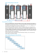
Figure 3 (page 14) shows watts consumed and relative workload at various workloads for each Power Regulator state. The system used in this test is an HP ProLiant DL380G5 with two Intel Xeon 5080 CPUs. Figure 3 Power and throughput in each of the HP Power Regulator modes Analysis of power consumption In HP Static High Performance Mode, power consumption ranges from 339 W in an idle state to 558 W at 100% utilization. This is an example of power consumption without the benefit of Power Regulator technology.
at 100% utilization. This is an example of the relative throughput without Power Regulator technology. The green bar shows the normalized throughput in HP Static Low Power Mode. In this mode, the throughput ranges from no throughput in an idle state to 0.79 at 80% utilization, and to 0.93 at 100% utilization. The blue bar shows the normalized throughput in HP Dynamic Power Savings Mode. In this mode, the throughput ranges from no throughput in an idle state to 0.79 at 80% utilization, and to 1.
Avoiding power provisioning errors For certain scenarios — unintentionally adding more systems and devices than the limit in a data center or power redundancy errors for unavailability of redundant power — any increase in power demand may lead to tripped breakers and unexpected downtime.
The power monitoring for Integrity servers is provided as follows: • For the regular and rackable Integrity servers, the power monitoring is provided for server only. • For Integrity Superdome2, the power monitoring is provided for complex, server enclosure, IOX enclosure, cell blade, and nPartition. ◦ Complex power is composed from the enclosures (server and IOX) that comprise the complex.
3 Managing power and cooling facilities in your data center Task: Importing power configuration from third-party management software HP Insight Control power management provides tools to read data from third-party management software in the form of SQL or web services queries. For each power management supported third-party management software, a command is provided to generate output in the text format suitable for use by the ipmimport command.
Figure 4 Power configuration information in a Microsoft Excel worksheet For a small data center, the data can be maintained manually in VIS format, where a column in the Excel worksheet represents a rack, and each cell is a slot position for a system. The VIS format is limited to only the physical hierarchy of the systems and devices in a data center. To convert data in the VIS format to text format, you can follow the instructions included in the ipmvis2txt manpage.
Task: Monitoring the power and cooling requirements of your IT equipment With Insight Control power management, you can optimize the power and cooling requirements of your data center efficiently. While each individual system, enclosure, PDU, or PDR in your data center can provide its power requirements and sometimes even a limited amount of power consumption history, it is still difficult to understand the power and cooling requirements for your data center in a holistic way.
1. Specify the position of each system or enclosure in a rack. a. If you maintain a database (for example, UCMDB or Excel worksheet) describing the grouping of systems into racks and racks into a grid in a data center, you can import it directly into power management. For more information on importing information into power management, see Task: Importing power configuration from external databases. b.
Task: Ensuring sufficient availability of power and cooling for your data center After configuring systems and devices in the data center, use the Power/Thermal Analysis view page to view diagnostic information on the power and cooling infrastructure. In the Power/Thermal Analysis view page: • Power Status Alerts are highlighted with severity icons to highlight the severity of the alert. Alerts for contained devices are aggregated to the top-level object displayed.
4. You will now analyze the power requirements for the combination of systems selected based on power consumption history. It is a best practice that you have enough power history to identify any potential cyclic peaks (such as end-of-month billing, or perhaps seasonal events). a. Choose the desired time frame (for example 1 year) and click Draw Graph. b. In the table that appears below the graph, determine the maximum power consumption for the set of systems as noted in the Group Peak Power Consumption.
report and from the Power Management Actions section of the Power/Thermal tab for a supported system. To decide on the level of alert and set the power alert threshold, HP recommends that you consult the power usage history in either of these reports.
Figure 6 Power Summary Meter While the enclosure may theoretically consume 35 A of power (the Calibrated Max Power based on the current configuration of the hardware), the maximum power observed since power management monitoring commenced was only 14 A (Peak Observed Power). The difference between Calibrated Max Power and Peak Observed Power, 35 A - 14 A = 21 A, represents the potential power that can be reclaimed when applying the power cap value.
1. 2. 3. 4. 5. Do I have sufficient power history collected for this system to make reasonable projections for future behavior? Several months of power history will likely ensure that you are seeing a typical depiction. However, if your computing demand has a seasonal component (such as the holidays, tax season, or end-of-the-fiscal-year spikes), you may want to analyze power history covering such time periods or allot additional headroom to avoid potential performance impacts of the cap.
Figure 8 Power Management Settings page of iLO 2 Then, you can determine the amount of power that must be reclaimed to make the necessary power/thermal capacity available in the rack. When applying caps, use the following guidelines: • As the power demand varies, Enclosure Dynamic Power Capping can share caps between systems. It is the first place to investigate when capping, and there is typically significant capacity that can be reclaimed by applying caps to enclosures.
Task: Generating power topology for BladeSystem enclosures through iPDUs When the BladeSystem enclosure is discovered and connected to an HP Intelligent PDU (iPDU), you can generate the power topology that supplies power to the BladeSystem through the iPDU. For this purpose, you do not need to create a rack with the BladeSystem enclosures and add the power connections to it to generate the power topology. You can either discover the BladeSystem enclosures or iPDUs to view the power topology.
this as a scheduled task with Scheduled Tasks facility of Systems Insight Manager. For information on managing tasks, see HP Systems Insight Manager User Guide. Task: Delegating rule authorization for operators You can authorize users, who perform the role of an operator, to run certain required rules using the Data Center Power Control facility. To authorize an operator to run a rule: 1. From the New Rule or Edit Rule section of the Data Center Power Control Rules page, click Permissions.
Task: Gracefully shutting down virtual machines Data Center Power Control allows you to stop or shut down the virtual machine (VM) hosts and guests using the Graceful Shutdown feature. To shut down VM hosts without any errors, you must stop or shut down the VM guests in a proper manner. The Graceful Shutdown feature shuts down the VM guests gracefully and then proceeds to shut down the VM hosts. The VMs that are configured for migrations are allowed to migrate before shutting down the guests.
4 Troubleshooting Recovering from error messages Insight Control power management fails to show the Power graph, and I receive the message Insight Control power management could not communicate with the Management Processor as it is not accessible. Solution: Make sure to resolve the following: • Connection to Management Processor timed out due to network problem or Management Processor being unreachable. • Mismatch of SSL ports between power management and management processor.
Insight Control power management fails to show the Power graph, and I receive the following message: Insight Control power management could not communicate with the Management Processor. Solution: Take the following steps to resolve the problem: 1. Make sure that the Management Processor of the system is discovered in Systems Insight Manager. NOTE: The system must be associated with iLO to view the power graph in power management. 2. 3.
Incorrect iLO credentials. When incorrect iLO credentials are entered for the servers in an enclosure, the progress bar window will run indefinitely during EDPC setting. Solution: Close the progress bar window. Provide the correct iLO credentials for the servers in the enclosure, and try setting EDPC. When DCPC Shutdown rule is invoked on a managed node, the system does not shut down.
Solution: Follow the workaround solution provided in the HP Systems Insight Manager 6.2 Release Notes available at: http://bizsupport2.austin.hp.com/bc/docs/support/SupportManual/ c02537450/c02537450.pdf. Operating system is not booted or does not support Power Regulation The OS Control Mode error is displayed for: • • Some or all of the blades within a NonStop BladeSystem, based on one of the following scenarios: ◦ The blade hardware model does not support Power Regulator.
supported for racks. The conditions that can prevent power history calculation are provided in the following list. For some of the conditions, suggested actions are provided to resolve the conditions. • Some power consumers do not have user-defined maximum power attributes. Solution: To assign maximum power attributes: 1. From the System tab of the system, expand the Power Management section, and click Configure. 2.
Miscellaneous When you rename the Systems Insight Manager discovered systems, enclosures, or racks in power management, the renamed names will be restored to the original names during the next discovery. Solution: Perform the following to resolve the problem: 1. From the Tools and Links tab of the System page, click Edit System Properties. 2. Select Prevent the Discovery process from changing this system name, and click OK.
5 Support and other resources Information to collect before contacting HP Be sure to have the following information available before you contact HP: • Software product name • Hardware product model number • Operating system type and version • Applicable error message • Third-party hardware or software • Technical support registration number (if applicable) How to contact HP Use the following methods to contact HP technical support: • In the United States, see the Customer Service or Contact HP
The service also provides access to software updates and reference manuals in electronic form as they are made available from HP. With this service, Insight Management customers benefit from expedited problem resolution as well as proactive notification and delivery of software updates. For more information about this service, see the following website: http://www.hp.com/services/insight Registration for this service takes place following online redemption of the license certificate.
Typographic conventions This document uses the following typographical conventions: Book title The title of a book. On the web, this can be a hyperlink to the book itself. Command A command name or command phrase, for example ls -a. Computer output Information displayed by the computer. Ctrl+x or Ctrl-x A key sequence that indicates you must hold down the keyboard key labeled Ctrl while you press the letter x. ENVIRONMENT VARIABLE The name of an environment variable, for example, PATH.
6 Documentation Feedback HP is committed to providing documentation that meets your needs. To help us improve the documentation, send any errors, suggestions, or comments to Documentation Feedback (docsfeedback@hp.com). Include the document title and part number, version number, or the URL when submitting your feedback.
A Capability matrix For using HP or third party non-managed or managed devices and servers, the available power management capabilities are given in the following table: Table 1 Insight Control power management capabilities Device Type Power Topology HP iPDU Intelligent Power Discovery Physical Location Power ON/ OFF/ Locator UID CYCLE Control Automatic ✓ rack placement when following best-practice wiring strategy ✓ Power History Power Capping Power Rack/Power Capacity/ Planning Requirements 24-h
Glossary branch circuit This represents a single output of a PDR circuit breaker and the PDU to monitor the actual circuit power consumption. breaker panel This represents the total group of breakers on a single breaker panel in a PDR. calibrated max power Sum of the maximum theoretical power consumption of all attached devices. capacity The available or maximum power limit of the power delivery device. Central Management Server Executes the Systems Insight Manager software.
HP Systems Insight Manager database The database that stores vital information about Systems Insight Manager, including users, systems, and toolboxes. license keys The contractual permissions granted by HP to the customer in the form of a coded embodiment of a license that represents a specific instance of a license. A single license can be represented by a single key or by a collection of keys. line voltage The line voltage of the data center that is delivered to the observed device.
power feed A top-level input of power from the Data center facility into the Power Management-observable power infrastructure. rack HP uses a universal rack to hold all supported rack-mount hardware. Racks are measured in U height (each U being a slot). The most common size is 42U, but HP also sells 14U, 22U, 36U, and 47U racks. See http://www.hp.com/go/rackandpower for options. rack PDU This represents the input power and multiple outputs to load segments, which can be two per management module.
Index C T concepts Data Center Power Control, 10 data centers, 7 Dynamic Power Capping, 16 Enclosure Dynamic Power Capping, 16 Power Capping, 16 power delivery devices, 7 power delivery hierarchy, 7 power history calculation, 7 power regulator, 12 power status alerts, 7 power summary meter, 7 power topology, 7 racks, 7 security properties, 11 task classifying systems by business criticality, 28 controlling the power of the PDU outlets, 27 defining rules for external events, 28 defining rules to reduce po