
HP LeftHand 4330 10 GbE SFP+ Installation Instructions (BQ891-96004, November 2012)


providing storage volumes, you must follow certain
steps to ensure an effective migration to the new
hardware configuration. The migration procedures in
this document cover one possible bonded configuration
— the ALB bond configured with two 10 GbE
interfaces as an ALB bonded pair.
TIP: HP recommends bonding network
interfaces for performance and failover. The
best bond to use depends on your network and
SAN configuration.
Bonding 10 GbE interfaces
After installing the 10 GbE upgrade, you have a
choice of supported bond configurations, as noted in
Table 2 (page 2).
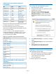
Table 2 Supported bonding configurations
ALB802.3adActive-Passive
Number of
ports x NIC
type
YesYesYes2 x 1 GbE
Yes (1)Yes (1)No3 x 1 GbE
Yes (1)Yes (1)No4 x 1 GbE
YesYesYes2 x 10 GbE
NoNoYes1 x 1 GbE + 1
x 10 GbE in
single bond
YesYesYesMultiple bonds
of same type
YesYesYesMultiple bonds
of different
type
Supported bonds with 10 GbE
The 4330 with the 10 GbE feature installed and
configured supports the following bond types:
• Adaptive Load Balancing (ALB) bond with the two
10 GbE Ethernet NICs
• Active-Passive bond with two 10 GbE Ethernet
NICs
• Active-Passive bond with 1 GbE NIC and 10 GbE
NIC
• Link Aggregation Dynamic Mode (802.3ad) bond
with two 10 GbE Ethernet NICs
Unsupported bonds with 10 GbE
The 4330 with the 10 GbE feature installed and
configured does not support the following bond types:
• Bonding two bonds
• ALB bond with 1 GbE NIC and 10 GbE NIC
• Link Aggregation Dynamic Mode bond with 1
GbE NIC and 10 GbE NIC
Plan for the migration (4330 already in a
management group)
Check the following items before starting the migration:
• Have compatible VIP addresses for the 10 GbE
switches that are running the 10 GbE ALB bond.
The SAN/iQ software requires each cluster to
have a valid VIP address. A valid VIP address is
one that is on the same subnet as the storage
systems. This VIP address must be valid after
updating the storage systems to the 10 GbE ALB
bond.
• Ensure that all network settings (Flow Control,
Frame Size (MTU)) for each NIC are consistent
across the switch, the storage system and the
client. The network settings must be configured
the same on each interface before creating a
bond.
Table 3 (page 2) shows a summary of the network
interfaces and bonds listed on the selected storage
system’s Network category TCP/IP tab window before
installing and configuring the 10 GbE adapter.
Table 4 (page 3) shows a summary list of those
interfaces and bonds after installing and configuring
the 10 GbE adapter.
NOTE: The SAN/iQ communication interface
in both configurations is Bond0.
Table 3 storage system network configuration
pre-migration
ModeSpeedNIC
Slave (bond0)1 GbEFlexLOM:Port1
Slave (bond0)1 GbEFlexLOM:Port2
Slave (bond1)1 GbEFlexLOM:Port3
Slave (bond1)1 GbEFlexLOM:Port4
Logical Failover
Device (ALB)
1 GbEBond0 Type
Logical Failover
Device (ALB)
1 GbEBond1 Type
Page 2