
9.5.01 HP P4000 SAN Solution User Guide (AX696-96168, February 2012)
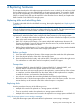


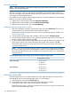

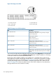
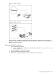
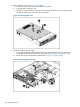
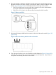
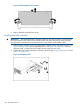

Figure 116 Storage server LEDs
2. System health LED1. Front UID/LED switch
4. NIC 2 activity LED3. NIC 1 activity LED
5. Power LED switch
Table 70 Storage server LED descriptions
DescriptionLED
Steady blue: Identification
Flashing blue: The system is being remotely managed
Front UID/LED switch
Off: No identification
Steady green: Healthy
Red: Critical error
System health LED
Amber: Non-critical error
Steady green: Linked to the network
Flashing green: Linked to and activity on the network
NIC 1 activity LED
Off: No connection
Steady green: Linked to the network
Flashing green: Linked to and activity on the network
NIC 2 activity LED
Off: No connection
Steady green: The system has AC power and is turned on
Steady amber: The system has AC power but in standby
mode
Power LED switch
You can also check the Hardware Information tab in the CMC (select Diagnostics for the applicable
storage system and then select the Hardware Information tab). If a RAID controller is not working,
it will not be visible on the Hardware Information tab.
Because there are two RAID controllers in the P4900 G2, it is important to know which one is
being replaced. The RAID controller that manages drives 1–4 and is the OS partition is installed
in the PCIex16 slot of the riser assembly(Figure 117 (page 247)) and is called Card 1. The RAID
controller that manages drives 5–8 is installed in the bottom PCIex8 slot and is called Card 2
(Figure 118 (page 247)). Review the Alarms section of the CMC to determine if any alarms have
been generated for the cache module or battery.
246 Replacing hardware