Technical white paper HP logical server management best practices Table of contents Introduction ..................................................................................................................................3 Logical server overview .................................................................................................................3 Naming conventions .....................................................................................................................
Figure Figure Figure Figure Figure Figure Figure Figure Figure Figure Figure Figure Figure Figure Figure Figure Figure Figure Figure Figure Figure Figure Figure Figure Figure Figure Figure Figure Figure Figure Figure Figure Figure Figure Figure Figure Figure Figure Figure Figure Figure Figure Figure Figure Figure Figure Figure Figure Figure Figure Figure Figure 1: HP logical server technology .............................................................................................................
Introduction NOTE This document was originally written for the 6.3 Insight Dynamics/Matrix Operating Environment. It has been refreshed to update product names and links to other documents. Although the contents and screenshots are based on Matrix OE 6.3, most of the information in this white paper applies to 7.1 and 7.2 as well. Effort has been taken to point out information that no longer applies to Matrix OE 7.1 and 7.2.
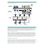
Figure 1: HP logical server technology Logical server (container) layer Logical server management abstraction Software abstraction layer VM VM Hypervisor Physical layer Server Server VM VM Hypervisor Server Server Physical layer—hardware abstraction (Virtual Connect domain) RDMA Cluster network LAN IP network SAN SAN Storage network The logical server can be activated either directly on a physical server blade (using Virtual Connect) or on a virtual machine (VM).
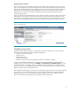
Logical server names When creating a logical server through the wizard, the administrator is able to specify various names, as shown in Figure 2. The Logical Server Name is a brief descriptive string, while the Description field can provide more detail. Logical servers are defined within a specific portability group, and the name must be unique within that scope. This name is distinct from the hostname that will be applied to the server once it has an Operating System installed.
Hostnames Hostnames need to conform to the restrictions imposed by the appropriate operating system environment. The recommendation for specifying hostnames for logical servers is to choose a name associated with the operating system and application, rather than a name related to a physical blade. The hostname will move with the logical server. For example, the logical server may be activated on a virtual machine hosted by System A, and later moved to the hypervisor on System B.
Figure 3: Network names in Virtual Connect Enterprise Manager As shown in Figure 4, the logical server interface also provides a free-form Description string which can be used for additional comments regarding the network choices. The string can be specified at initial logical server creation, or later using the Modify menu option for logical servers. The MAC Address is display only, and is set to the value allocated by the logical server software from the pool of Virtual Connect MAC Addresses.
Figure 4: Network names known when creating logical server SAN fabric names It is recommended that the fabric names and descriptive properties information be chosen to enable correlation to storage configuration through interfaces used by the storage administrator (such as Command View EVA and SAN management solutions).
Figure 5: Fabric names in Virtual Connect Enterprise Manager Matrix is integrated with the bundled HP Storage Provisioning Manager (SPM) solution. In the version 6.3 release, SPM was aware of SAN fabrics through the specification of SAN IDs (which needed to correlate with the VCM definitions). With the 7.0 and later releases, SPM is able to automate SAN operations in a Brocade SAN environment (discovering SAN fabrics for import and performing zoning).
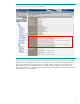
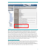
Figure 6: Fabric names in HP Storage Provisioning Manager 6.3 The fabric names are automatically populated from Matrix OE to SPM (where they appear as SAN IDs as shown in Figure 6). The SAN IDs are used when configuring the connectivity of a given array, or specifying volume presentation. Note that SPM may have additional SAN IDs defined (via the Define SAN IDs button shown at the bottom of Figure 6) that are not known to Virtual Connect Manager, VCEM, and Matrix OE.
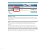
Figure 7: Fabric names known when creating storage pool entry As shown in Figure 7, the Matrix OE software allocates a WWN for each of the logical server HBA ports defined (shown in the Server WWN column). These WWNs would be shared with the storage administrator for storage presentation and SAN zoning (or SPM can automate the presentation and zoning, or even the on-demand provisioning of the storage volumes).
appropriate logical servers (and can auto-generate storage pool entries for SAN volumes, fulfilling them with stoage from SPM, either pre-provisioned and imported or on-demand provisioned). MatrixIO provides mechanisms to define the logical server use of a local disk (with the caveat that the flexible movement capabilities are restricted; the OS/application would need to be installed on a new target blade if movement is required).
Storage specification The specification of storage for a logical server can be done in one of several ways, based on the administrator needs and preferences. The system administrator can specify the storage LUN information for each logical server individually at the time of creation. Logical server storage pool entries are created as required, and the administrator can choose if they are populated into the storage pool for the portability group or only accessible through the logical server definition.
Import is valuable when a workload is already running in a virtual machine or on a physical blade, and can be used to create a logical server representing a virtual machine hypervisor. There are parallels between storage provisioning in a virtual environment and a physical blade environment. For virtual machines, it is common for the storage administrator to pre-allocate a large volume on the SAN and the server administrator consumes space as required (for example, as virtual machines are created).
Storage provisioning interactions Figure 9 shows the typical flow of tasks and interactions, wherein a server administrator creates a logical server, which contains information about the desired storage resources (size, redundancy, multi-pathing, intended OS, and so on) as well as the WWNs allocated for the server HBAs from the pool of Virtual Connect WWNs managed by VCEM.
provisioning mechanisms in the customer environment (e.g., a formal request tracking system, email, or other mechanisms). In addition to manual entry of information, Matrix OE provides the ability to export and import storage definitions in XML files (automating the population of storage details into the logical server storage pool entries).
Figure 10: Logical server storage provisioning (without SPM) Planning discussions vary by customer, but typically involve anticipated storage needs for servers required over the next several months or quarters. Many environments define specific tiers of usage, and may allocate storage in standard sizes or have policies for boot volume allocation (perhaps differing by OS).
Figure 11: Logical server storage provisioning with SPM Figure 11 shows the automated population of storage details as well as the reduction in elapsed time between request and response. As noted, the storage catalog can be pre-populated with volumes (resulting in the fastest elapsed time) or the storage administrator could choose to provision individual requests.
provisioning for the HP 3PAR StoreServ and HP P6000/EVA. No explicit storage validation is required with SPM, since it has returned information from the storage devices. Figure 12 shows the “Validate” button which is available when viewing or modifying the logical storage for a specific logical server. The typical use case would be to save the logical server definition with the desired storage specification.
storage pool entry can work with the storage administrator for necessary corrections (e.g., if a volume was intended for use by Linux but was presented for Windows use). Having validated the storage volume information is acceptable, the server administrator can mark the ports as ready (assuming the storage administrator has completed SAN zoning prior to returning the storage details). If SAN zoning has not yet been successfully completed, the volumes can later be marked ready when that completes.
Figure 14: Managing storage pools When defining a logical server, the server administrator can choose an appropriate storage pool entry, proceeding without requiring interaction with the storage administrator. Figure 15 shows a logical server creation using an existing storage pool entry. Note that the name and description of each possible entry in shown, helping the administrator make an appropriate choice (and demonstrating why it is important to have helpful names and descriptions).
Storage pool entry considerations There are a variety of ways logical server storage pool entries can be used, and the server administrator should balance the value of multi-pathing, support for multi-initiator NPIV, the need for multiple logical servers to access the same data volumes, and the convenience of OS installation techniques. Consider first the need for multi-pathing. Many customers have requirements to configure multiple paths to boot and data volumes.
Figure 17: Logical servers with private boot, shared data, multi-pathing via multiple HBA ports Logical Server A HBA HBA HBA HBA Port Port Port Port 1 2 3 4 WWN WWN WWN WWN Port Port Port Port 1 2 3 4 Fabric B A B C D Logical Server B HBA HBA HBA HBA Fabric A 1 2 3 4 WWN WWN WWN WWN E F G H Fabric C Fabric D 1 2 3 4 Array A C1 C2 Entry 3 5 GB boot vol, Windows, HBA WWNs E, F Logical Server Storage Pool Entries vdisk 2 vdisk 1 is a 5 GB boot volume, Windows; presented over both ports of ea
Figure 18: Modify logical server storage pools As noted earlier (and shown previously in Figure 14), the administrator can view all entries across portability groups, or focus in on a particular portability group (and further refine the storage pool entries shown via filtering). The administrator clicks the “Add Entry” button to create a storage pool entry. Figure 18 also shows the three choices available when defining a logical server storage pool entry (in advance of logical server definition).
that WWN with another reserved Virtual Connect WWN, if appropriate (e.g., if the storage administrator has reserved a set of initiator WWNs and created, presented, and zoned storage – but not created storage pool entries to represent those storage volumes, and is not using the Storage Provisioning Manager storage catalog). NOTE: If the administrator leaves the host mode as unspecified, Matrix OE will match for storage which can support all possible host modes (including Windows 2008).
If the administrator defining this storage pool entry has the ability to create, present, and zone storage, they could choose to do so now and populate the relevant details. Otherwise, the entry can be saved and later modified when storage details are available. The use of the “Validate” button was discussed in an earlier section of this white paper. Since this storage pool entry is being defined from the storage pool screen, it is automatically placed into the appropriate storage pool.
Figure 21: Using the Storage tab to modify associated storage pool entries not in the pool Clicking the “Modify” button to the right of each row in the Storage Assignments table (shown in Figure 21) enables the user to enter the storage details (as shown in Figure 20). The Storage pool entry export and import section of this white paper discusses use of the command line interface to import storage details (avoiding such manual editing).
Figure 22: Add Storage Pool Entry (using SPM storage catalog) Figure 22 shows a storage pool entry for a web server, containing ports defined for two fabrics, and two volumes (one 10 GB boot LUN with redundant paths, and one 40 GB data LUN). Matrix OE has allocated the server WWNs for both HBA ports defined for this entry (shown in the Manage Server WWNs table at the bottom of the screen). All volumes should be initially made visible to the initiator HBA WWNs by selecting the “Masked” checkbox.
The administrator would select a candidate for each volume and save the storage pool entry. Any necessary adjustments to host mode or LUN masking would be initiated. The status of the storage pool entry in the Manage Storage Pool interface would reflect “Presentation Initiated” and then “Presentation Completed”. If the storage administrator has not enabled automated LUN masking of the volume, the status would be “Presentation Pending” until the storage administrator manually performs the necessary changes.
Figure 24: Defining a storage pool entry (view only volumes from pre-populated SPM catalog) The volume information is specified as with other storage types (in this case a 10 GB boot volume). Redundancy for this type of storage pool entry must be the same across all volumes (i.e., one volume cannot use redundancy while a second volume does not). The “Show Candidates” button is used in the same manner: select a volume, show the candidates and make a selection from the list.
Figure 25: Storage pool entry fabric information from pre-populated SPM storage catalog Figure 25 shows that the fabric information is now populated into the storage pool entry, an indication that the volume has redundant paths, and also shows the Storage Port WWN and LUN information. The administrator can review the default Storage Port WWNs and select a different WWN if appropriate at this time.
they create the storage pool entries and enter the corresponding details into the storage pool entries (e.g., target storage controller WWNs and LUN numbers). This first method of entering storage details in the storage pool entry screens also works in environments where storage requests may be made through formal request tracking systems (or even informal emails to storage administrators) and details regarding the resultant allocated storage are later returned.
Figure 26: Exporting and importing storage pool entry definitions Creation of storage pool entries in advance requires that the storage administrator anticipate the types of storage required, and the initiator WWNs needed for storage presentation and SAN zoning are made available through another option of the lsmutil command (-reserve -wwn). When the lsmutil -import -spe command is used, Matrix OE will match the storage pool entries in the XML file based on the element.
no details yet supplied, the storage target tags would be missing and it is that information which would be added to the file prior to import. The element was added with the 6.3 release and represents the units for storage (MB, GB); the below example illustrates the two variants. PAGE 351 2 40 GB 0 0 RAID0 false false false 1 50:00:1F:E1:50:03:27:6D 2 PRIMARY 1
The XML file contains a number of elements, each with various tagged properties and a number of and elements. As noted earlier, the is used for matching. When the XML file is used to facilitate communication between the server and storage administrators, the storage pool entry would be left unmodified (as would many of the properties such as , , , and ).
Figure 27: Manage Tags button on the Manage Storage Pool screen The tags (such as those shown defined in Figure 28) are available for selection when defining storage pool entries in any of the portability groups. Figure 28: Multiple tags defined The tags defined in Matrix OE 6.3 and earlier are automatically propagated to HP Storage Provisioning Manager (placed in the HP_LSM_TAG_Namespace). Figure 29 shows the tags now visible in SPM 6.3. HP Matrix OE 6.
Figure 29: Multiple tags in the HP Storage Provisioning Manager 6.3 Figure 29 also shows the “Define Tags” button available at the bottom of the SPM 6.3 Catalog screen. Figure 30 shows the available tags when defining a storage pool entry. As noted earlier, the tag values reflect a dictionary of terms which have meaning for the server and storage administrators. NOTE: It is not necessary to use tags to describe attributes which are formally modeled as part of a storage definition (e.g.
Figure 30: Selecting tags while defining a storage pool entry Customers using the infrastructure orchestration capabilities of Matrix OE can specify tag values for storage volume used within templates and have those matched against the tag values on storage pool entries. Figure 31 shows the specification of tags in the Insight Orchestration Designer storage configuration interface.
option of specifying a portability group including both servers using Virtual Connect and VMware ESX or HyperV virtual machine hosts (to support cross-technology logical servers). When creating logical servers that will be virtual machines, it is necessary to specify their storage requirements. Matrix OE supports virtual machines backed by files in the hypervisor‟s file system, so storage definition involves specifying the number of files and their sizes.
Figure 33: Creating a file-based storage entry for a virtual machine logical server Figure 34 shows the resultant two volumes visible in the Create Logical Server wizard (after clicking the “Save” button in Figure 33). The storage entry can be modified as appropriate to add or remove volumes/files using the “Modify” button. In this example, the ESX data store is a Fibre Channel SAN disk provided via SVSP (the HP SAN Virtualization Services Platform).
In addition to this file-based storage definition for the VM, the Matrix OE supports RDM (Raw Device Mapping) in the VMware, Microsoft, and HP Integrity VM environments. Please see the compatibility guide for more information. This is a key enabler for cross-technology logical servers which can move from a physical system to a virtual system and back to a physical system. Each VM can have multiple RDM volumes, represented by one or more storage pool entries.
Figure 36: Storage pool entry choices when defining storage for a virtual machine logical server If no pre-defined storage is available in the pool, the storage can be defined from step 3 of the Create Logical Server wizard using the “Create Storage Entry” button (with the storage type specified as “SAN Storage Entry”). Figure 37 shows the storage entry creation screen (with the option to add the storage to the storage pool).
Figure 37: Creating a storage entry when defining a virtual machine logical server The storage is defined within the same portability group as the logical server(s) that will consume the storage. Ports can be added via the “Add Port” button. The fabric need not be specified as it will be determined by the hypervisor hosts selected (as with the server WWN values). Volumes are specified with standard attributes such as redundancy, size, RAID level, and one field unique to VM storage (Access).
Figure 38: Modifying a logical server with virtual machine RDM storage Figure 39 shows the Storage Port WWN and LUN information being added to the storage pool entry for the logical server which will be instantiated as a virtual machine.
Figure 39: Adding Storage Port WWN and LUN information Once the storage entry is saved with the appropriate storage details and the Ready checkbox selected for each potential target (indicating storage has been created, presented, and zoned), it is available for use when the logical server is instantiated onto a virtual machine (and perhaps later onto a physical system as the administrator takes advantage of the Matrix OE capabilities for flexible movement of cross-technology logical servers).
(which is not affiliated with a logical server), and add new volumes meeting the needs. This preserves the initiator WWNs in the storage pool entry (and any SAN zoning which has been done for those initiators to specific array controller target ports). If the storage pool entry were deleted, the initiator WWN could be re-used (and thus the storage administrator would want to appropriately adjust zoning to ensure the next user of those initiator WWNs isn‟t granted access inappropriately).
It can be helpful to do the following: 1. Name the zone the same as the storage pool entry name (or vice-versa). This makes it easier to keep track of the alignment between the storage pool entries and the zone names within the fabric. 2. If possible, prefix the name of the storage volumes created on the disk array with the name of the storage pool entry suffixed by the LUN number or a simple index value.
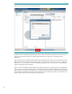
Figure 40: Command View EVA accessing Add host tab Figure 41 shows adding a host via Command View EVA. The HBA Port World Wide Name can be directly entered in the Basic Settings section, along with a name and the desired operating system. The Comments field can capture relevant information. The name field might be a hostname selected by the system administrator to be affiliated with the OS and application workload intended for this logical server, or another general name.
Figure 42: Command View EVA accessing the Presentation tab for a created Vdisk Figure 43 shows the presentation of the Vdisk. The Exchange Server Boot Vdisk has been selected in the left-hand tree, the Host is selected from the list displayed in the window, and the Present Vdisk button (in the upper left corner) is pressed.
Figure 43: Presenting Vdisk to created host Figure 44 shows the result of having presented both the boot and data volumes. Figure 44: Resulting presentations Detailed information regarding Command View EVA is available in the User Guide online at http://h10032.www1.hp.com/ctg/Manual/c02492843.pdf.
P2000/MSA Disk Arrays The HP P2000/MSA family of disk arrays includes Fibre Channel versions of MSA2000 G1 and G2 arrays (e.g., MSA2000fc and MSA2300fc) and P2000 G3 MSA arrays (e.g., P2000 G3 FC MSA and P2000 G3 FC/iSCSI MSA Combo Controller) which are supported in the logical server environment. The P2000/MSA family is managed through a command line interface or the Storage Management Utility (SMU), a Web-based interface.
Figure 45a: Adding a host in the MSA2300fc with the Storage Management Utility Figure 45b: Adding a host in the P2000 G3 FC MSA with the Storage Management Utility Figure 46 shows the interface to create a volume, accessed from the Provisioning menu with the Vdisk selected. The volume is given a name, and the size is specified. LUN and access information can be specified here, but will also be specified in the explicit mapping (as shown in Figure 47).
Figure 46a: Creating a volume for the MSA2300fc Figure 46b: Creating a volume for the P2000 G3 FC MSA Figure 47 shows the result of having created a 5 GB boot volume and a 30 GB data volume (both shown under the vd Vdisk). To present the storage volume to the Exchange3 host, the Explicit Mapping item is chosen from the Provisioning menu (as shown in Figure 47).
Figure 47a: Volumes created, accessing the explicit mapping, for the MSA2300fc Figure 47b: Volumes created, accessing the explicit mapping, for the P2000 G3 FC MSA 55
Figure 48 shows the explicit mapping for a volume. The upper table shows the various hosts, and Exchange3 is selected. The Map checkbox is selected, and the volume is mapped to all four ports, giving read-write access as LUN 1.
Boot from SAN Configuring a logical server to boot from SAN utilizes the same basic procedure as boot from SAN for any blade server. However, many of the necessary steps are handled for the system administrator by the Virtual Connect software. General boot from SAN capabilities are described at http://h18006.www1.hp.com/storage/networking/bootsan.html, along with documentation specific to the arrays and operating system environments.
and thus it is necessary to annotate the collected server information with local disk information. Local disk boot volumes are not represented by storage pool entries. Rather, the server is annotated to indicate is has a local disk with particular properties. These annotations are done through the following steps: 1. Use the lsmutil -export –an –file filename.xml command to create a filename.xml file containing the servers that can support a local disk. 2. Edit the filename.
set to the appropriate value, generally 1. size of the local disk in MB or GB set to false The value can be set as appropriate for the customer environment. The other fields should be left unspecified (e.g., , , ). The fields should not be changed (e.g., server name, UUID, and portability group).
Prints a short list in ASCII format to sysout or to the specified file of all the compute resources in the Matrix OE database or the names contained in the comma/semicolon separated list. If a type is specified, only those types of compute resources will be displayed. If no option is selected, all compute resources are displayed. The short list will contain the Name, Type (VcBlade, EsxHost, EsxVM, etc.) and Status.
lsmutil -reserve -wwn [WWN | DomainGroupName Number of WWNs] [-help] Preallocate the supplied WWN or preallocate the specified number of initiator WWNs for the specified Virtual Connect Domain Group. When only "lsmutil -reserve -wwn" is supplied, the list of available Virtual Domain Groups on the CMS will be displayed. lsmutil -unreserve -wwn WWNs [-help] Unreserve the WWNs listed in comma/semicolon separated list. If a WWN is owned by LSARES it is unreserved.
More details regarding OS installation (including VMware ESX installation) are available in Chapter 3 of the HP Insight Control server deployment User Guide, available at http://bizsupport1.austin.hp.com/bc/docs/support/SupportManual/c02048553/c02048553.pdf . The key point is to ensure the OS is deployed to the intended boot volume (and not mistakenly to a data volume).
Logical servers enable a common approach to planning, deployment, adjustment, and management, whether the server OS and workloads are hosted directly on a physical server, or on a hosted virtual machine. Logical servers are defined by server profiles that are easily created and freely moved across physical and virtual machines. Logical servers are based on the proven technologies such as HP Virtual Connect.
Glossary 64 Central management server (CMS) A system in the management domain that executes the HP Systems Insight Manager software. All central operations within HP Systems Insight Manager are initiated from this system. The Matrix OE and HP Storage Provisioning Manager software solutions run on the CMS.
For more information HP Matrix Operating Environment and HP CloudSystem Matrix Information on HP Matrix Operating Environment (including infrastructure orchestration and HP Storage Provisioning Manager) is available at http://www.hp.com/go/matrixoe. A variety of information is available at http://www.hp.
HP Virtual Connect, HP BladeSystem, and HP CloudSystem Information regarding HP Virtual Connect is available at http://www.hp.com/go/virtualconnect with documentation available from http://www.hp.com/go/bladesystem (click on the “Technical Resources” link in the left-hand list). The HP Virtual Connect Technology Guide is available at http://h20195.www2.hp.com/V2/GetPDF.aspx/4AA0-5821ENW.pdf . The HP Virtual Connect for BladeSystem c-Class User Guide is available at http://bizsupport2.austin.hp.
b. HP StorageWorks 2000 G2 Modular Smart Array reference guide http://bizsupport2.austin.hp.com/bc/docs/support/SupportManual/c01756042/c01 756042.pdf c. HP StorageWorks 2000 G2 Modular Smart Array CLI reference guide http://bizsupport1.austin.hp.com/bc/docs/support/SupportManual/c01755995/c01 755995.pdf Manuals for All HP Disk Storage Systems a. http://h20000.www2.hp.com/bizsupport/TechSupport/Product.