
HP Logical Server Management Best Practices
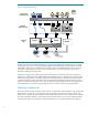
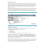
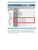
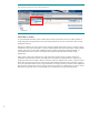
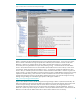
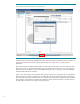
Figure 1: HP logical server technology ............................................................................................................. 4
Figure 2: Create logical server ........................................................................................................................ 5
Figure 3: Network names in Virtual Connect Enterprise Manager ........................................................................ 7
Figure 4: Network names known when creating logical server ............................................................................ 8
Figure 5: Fabric names in Virtual Connect Enterprise Manager ........................................................................... 9
Figure 6: Fabric names in HP Storage Provisioning Manager ............................................................................ 10
Figure 7: Fabric names known when creating storage pool entry ...................................................................... 11
Figure 8: Flexible growth: Provision new node quickly with logical server creation and activation ......................... 12
Figure 9: Server and storage administrator interactions .................................................................................... 15
Figure 10: Logical server storage provisioning (without SPM) ............................................................................ 17
Figure 11: Logical server storage provisioning with SPM .................................................................................. 18
Figure 12: Logical server storage information has been added and validation results shown ................................ 19
Figure 13: Menu access to manage logical server storage pools ....................................................................... 20
Figure 14: Managing storage pools ............................................................................................................... 21
Figure 15: Defining a logical server to use an existing storage pool entry .......................................................... 21
Figure 16: A logical server with redundant HBA ports, SAN fabrics, and storage controllers ................................ 22
Figure 17: Logical servers with private boot, shared data, multi-pathing via multiple HBA ports ............................ 23
Figure 18: Modify logical server storage pools ............................................................................................... 24
Figure 19: Add Storage Pool Entry (standard SAN storage entry, no SPM) ......................................................... 25
Figure 20: Modify storage entry enables editing of storage details .................................................................... 26
Figure 21: Using the Storage tab to modify associated storage pool entries not in the pool .................................. 27
Figure 22: Add Storage Pool Entry (using SPM storage catalog) ........................................................................ 28
Figure 23: Defining a storage pool entry (candidates selected from SPM storage catalog) .................................... 29
Figure 24: Defining a storage pool entry (view only volumes from pre-populated SPM catalog)............................. 30
Figure 25: Storage pool entry fabric information from pre-populated SPM storage catalog ................................... 31
Figure 26: Exporting and importing storage pool entry definitions ..................................................................... 33
Figure 27: Manage Tags button on the Manage Storage Pool screen ................................................................ 37
Figure 28: Multiple tags defined .................................................................................................................... 37
Figure 29: Multiple tags in the HP Storage Provisioning Manager ..................................................................... 38
Figure 30: Selecting tags while defining a storage pool entry ........................................................................... 39
Figure 31: Specifying tags within Insight Orchestration Designer storage configuration ........................................ 39
Figure 32: Creating a logical server with virtual machine file-based storage ....................................................... 40
Figure 33: Creating a file-based storage entry for a virtual machine logical server .............................................. 41
Figure 34: Creating a virtual machine logical server with file-based storage ....................................................... 41
Figure 35: Storage pool entry choices when defining storage for a virtual machine logical server ......................... 42
Figure 36: Storage pool entry choices when defining storage for a virtual machine logical server ......................... 43
Figure 37: Creating a storage entry when defining a virtual machine logical server ............................................ 44
Figure 38: Modifying a logical server with virtual machine RDM storage ........................................................... 45
Figure 39: Adding Storage Port WWN and LUN information ........................................................................... 46
Figure 40: Command View EVA accessing Add host tab .................................................................................. 49
Figure 41: Command View EVA adding a host by HBA WWN ........................................................................ 49
Figure 42: Command View EVA accessing the Presentation tab for a created Vdisk ............................................ 50
Figure 43: Presenting Vdisk to created host ..................................................................................................... 51
Figure 44: Resulting presentations ................................................................................................................. 51
Figure 45a: Adding a host in the MSA2300fc with the Storage Management Utility ............................................ 53
Figure 45b: Adding a host in the P2000 G3 FC MSA with the Storage Management Utility ................................. 53
Figure 46a: Creating a volume for the MSA2300fc ......................................................................................... 54
Figure 46b: Creating a volume for the P2000 G3 FC MSA .............................................................................. 54
Figure 47a: Volumes created, accessing the explicit mapping, for the MSA2300fc ............................................. 55
Figure 47b: Volumes created, accessing the explicit mapping, for the P2000 G3 FC MSA .................................. 55
Figure 48a: Explicit mapping of the volume to host for the MSA2300fc ............................................................. 56
Figure 48b: Explicit mapping of the volume to host for the P2000 G3 FC MSA .................................................. 56