Building Disaster Recovery Serviceguard Solutions Using Metrocluster with Continuous Access EVA A.05.
Legal Notices © Copyright 1995-2013 Hewlett-Packard Development Company, L.P. Confidential computer software. Valid license from HP required for possession, use, or copying. Consistent with FAR 12.211 and 12.212, Commercial Computer Software, Computer Software Documentation, and Technical Data for Commercial Items are licensed to the U.S. Government under vendor’s standard commercial license. The information contained herein is subject to change without notice.
Contents 1 Introduction...............................................................................................8 Overview of EVA and HP P6000/EVA Continuous Access concepts................................................8 Copy sets............................................................................................................................8 Data replication Groups (DR Groups).....................................................................................8 Write modes...............
Creating a Serviceguard cluster with sites configured..............................................................34 Configuring the Cluster File System Multi-node Package...........................................................35 Easy deployment of site-aware cluster and CFS cluster using cmdeploycl....................................35 Setting up replication..............................................................................................................
Cluster Node Maintenance.................................................................................................61 Maintaining the site...........................................................................................................62 Moving the Site Controller package to a node at the local site.................................................62 Maintaining Site Controller package....................................................................................
Configuring the storage device for complex workload at the target disk site using SG SMS CFS or CVM............................................................................................................................96 Migrating complex workloads using legacy SG SMS CVM/CFS packages to modular packages with minimal downtime.......................................................................................................96 G Configuring Oracle RAC in SADTA........................................
Configuring the Site Controller package..............................................................................125 Configuring the Site Safety Latch Dependencies...................................................................125 Starting the disaster tolerant Oracle RAC database with ASM in the Metrocluster.....................126 Failure scenarios in Metrocluster for RAC.................................................................................126 Oracle RAC database Failure ................
1 Introduction This document describes how to configure data replication solutions using HP P6000/EVA disk Arrays to provide disaster recovery for Serviceguard clusters over long distances. It also gives an overview of the HP P6000/EVA Continuous Access software and the additional files that integrate HP P6000/EVA disk Arrays with Metrocluster.
The replicating direction of a DR group is always from a source to a destination. In bidirectional replication, an array can have both source and destination virtual disks that will reside in separate DR groups. That is, one virtual disk cannot be both a source and destination simultaneously. Bidirectional replication enables you to use both arrays for primary storage while they provide disaster protection for another site.
DR Group write history log The DR group write history log is a virtual disk that stores a DR group's host write data. The log is created when you create the DR group. Once the log is created, it cannot be moved. In synchronous mode or basic asynchronous mode, the DR group write history log stores data when replication to the destination DR group is stopped because the destination DR group is unavailable or suspended. This process is called logging.
shutdown of the system before the redundant system takes over. An unplanned failover occurs when a failure or outage occurs that may not allow an orderly transition of roles. NOTE: Failover can take other forms: • Controller failover — The process that occurs when one controller in a pair assumes the workload of a failed or redirected controller in the same array. • Fabric or path failover — I/O operations transfer from one fabric or path to another.
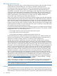
www.hp.com/support/manual—>storage -> Storage Software -> Storage Replication Software -> HP P6000/EVA Continuous Access Software. Overview of a Metrocluster with HP P6000/EVA Continuous Access configuration A Metrocluster is configured with the nodes at Site A and Site B. When Site A and Site B form a Metrocluster, a third location is required where Quorum Server or arbitrator nodes must be configured.
Figure 1 Sample Configuration of Metrocluster with Continuous Access EVA Quorum Server A B Node 1 Node 2 Node 3 Node 4 Metrocluster Site A Router Site B Router Synchronous / Enhanced Asynchronous EVA Disk Array EVA Disk Array DC1 for App A DC2 for App B DC1 for App B DC2 for App A Figure 1 depicts an example of two applications distributed in a Metrocluster with Continuous Access EVA environment balancing the server and replication load.
2 Configuring an application in a Metrocluster environment Installing the necessary hardware and software When the following procedures are complete, an adoptive node will be able to access the data belonging to a package after it fails over. Setting up the storage hardware 1. 2. 3. Before you configure Metrocluster with Continuous Access EVA, you must correctly cable the EVA with redundant paths to each node in the cluster that will run packages accessing data on the array.
# cmquerycl -v -C /etc/cmcluster/ -n -n For example, for cmapplyconf # cmapplyconf -v -C /etc/cmcluster/ NOTE: You must not configure a HP P6000/EVA Continuous Access Vdisk belonging to a DR Group as a cluster lock disk. A cluster lock disk must always be writable. Since it cannot be guaranteed that either half of a paired volume is always writable, neither half may be used as a cluster lock disk.
site_preferred_manual for the failover_policy attribute in the Metrocluster package configuration file. NOTE: For a Metrocluster package, HP recommends that you set the failover_policy parameter to site_preferred. Setting up the replication Creating VDISKs and DR groups using HP P6000 command view The P6000 Command View is a web-based tool to configure, manage, and monitor virtual disks and DR groups as shown in Figure 2 (page 16).
ls DR_GROUP “\Data Replication\DRG_DB1” NOTE: For more detailed information on the SSSU commands used in the sample input file, see /opt/cmcluster/toolkit/SGCAEVA/Samples/Readme.sssu_sample_input Perform the following steps when copying and editing the sample file: 1. Copy the sample file /opt/cmcluster/toolkit/SGCAEVA/Samples/ sssu_sample_input to the /etc/dtsconf directory. # cp /opt/cmcluster/toolkit/SGCAEVA/Samples/sssu_sample_input/etc/dtsconf/sssu_input 2. 3. Customize the file sssu_input.
Creating the Management Server list On a host that resides on the same data center as the active management server, create the Management Server list using an input file. To create use the following steps: 1. Create a configuration input file (A template of this file is available in /opt/cmcluster/ toolkit/SGCAEVA/smiseva.conf). An example of the smiseva.conf file is given in “smiseva.conf file” (page 86) 2. Copy the template file /opt/cmcluster/toolkit/SGCAEVA/smiseva.conf to the /etc/dtsconf/ directory.
Adding or updating Management Server information To add or update individual Management Server login information to the map file, use the following command options shown in Table 2: smispasswd -h -n -p -u -s Table 2 Individual Management Server information Command Options Description -h This is either a DNS resolvable hostname or IP address of the Management Server -n This is the name space configured for the S
1. 2. Create a configuration input file. This file will contain the names of storage pairs and DR groups. (A template of this file is available in /opt/cmcluster/toolkit/SGCAEVA/ mceva.conf). An example of the mceva.conf file is given in Appendix D: “mceva.conf file” (page 87). Copy the template file /opt/cmcluster/toolkit/SGCA EVA/mceva.conf to the /etc/ dtsconf directory. # cp /opt/cmcluster/toolkit/SGCAEVA/mceva.conf /etc/dtsconf/mceva.conf 3. 4. 5.
NOTE: Before running the evadiscovery command, the management server configuration must be completed using the smispasswd. Otherwise, the evadiscovery command, will fail. Similarly, whenever new Management Servers are added or the existing Server credentials are changed, generate and redistribute the map file to all Metrocluster clustered nodes. Configuring volume groups This section describes the required steps to create a volume group for use in a Metrocluster with Continuous Access EVA environment.
Figure 3 P6000/EVA Command View for the WWN identifier Configuring LVM volume group using Metrocluster with Continuous Access EVA Configuring volume groups To configure volume groups: 1. Define the appropriate Volume Groups on each node that might run the application package. Run the following commands: # mkdir /dev/ # mknod /dev//group c 64 0xnn0000 where the name /dev/ and the number nn are unique within the cluster.
7. Test the Volume Groups activation with exclusive option. # vgchange -a e /dev/ 8. Create a back-up config file that will contain the cluster ID on the disks/luns. # vgcfgbackup /dev/ 9. Deactivate the volume group. # vgchange -a n /dev/ 10. Use the vgexport command with the -p option to export the Volume Group on the primary system without removing the HP-UX device files. # vgexport -s -p -m /dev/ Make sure to copy the map files to all of the nodes.
NOTE: Exclusive activation must be used for all volume groups associated with packages that use EVA. In Metrocluster with Continuous Access EVA, only one node will have a Volume Group activated at any given time. Importing volume groups on nodes at the remote site Use the following procedure to import volume groups on all cluster nodes located at the site of the remote EVA. The sample script /opt/cmcluster/toolkit/SGCAEVA/Samples/mk2imports can be modified to automate these steps. 1.
Figure 4 P6000 Command View DR group properties Creating VxVM disk groups using Metrocluster with Continuous Access EVA To create disk groups, using VERITAS storage: 1. Initialize disks to be used with VxVM by running the vxdisksetup command only on the primary system. # /etc/vx/bin/vxdisksetup -i disk3 2. Create the disk group to be used with the vxdg command only on the primary system. # vxdg init logdata disk3 3. Verify the configuration. # vxdg list 4.
4. Import the disk group. # vxdg -tfC import 5. Start the logical volume in the disk group. # vxvol -g startall 6. Create a directory to mount the volume. # mkdir / 7. Mount the volume. # mount /dev/vx/dsk/// 8. Check to make sure the file system is present, then unmount the file system. # umount / 9. Deport the disk group. # vxdg deport Repeat steps 4 through 9 on all nodes in the remote site that require access to this disk group.
1. a. Run the following command to create a Metrocluster with Continuous Access EVA modular package configuration file: # cmmakepkg –m dts/mccaeva temp.config b. If the Metrocluster package uses ECMT Toolkit, then add the corresponding ECMT module. For example, for a Metrocluster ECMT Oracle toolkit modular package, run the following command: # cmmakepkg -m dts/mccaeva -m ecmt/oracle/oracle temp.config 2. Edit the following attributes in the temp.
4. Apply the package configuration file. # cmapplyconf -P temp.config NOTE: If external_pre_script is specified in a Metrocluster package configuration, the external_pre_script is executed after the execution of Metrocluster module scripts in package startup. Metrocluster module scripts are always executed first during package startup. 5. Run the package on a node in the Serviceguard cluster. # cmrunpkg -n 6. Enable global switching for the package.
Figure 6 Selecting Metrocluster module 5. 6. You will be prompted next to include any other toolkit modules. In case, application being configured has a Serviceguard toolkit, select the appropriate toolkit; otherwise, move to the next screen. Enter the package name. Metrocluster packages can be configured only as failover packages. Make sure that this option is selected as shown in Figure 7 (page 29) and then click Next. Figure 7 Configuring package name 7.
Figure 8 Selecting additional modules for the package 8. Review the node order in which the package will start, and modify other attributes, if needed. Click Next. Figure 9 Configuring generic failover attributes 9. 30 Configure the attributes for a Metrocluster package. All the mandatory attributes (marked with *) must be accurately filled.
a. b. c. d. Select Application start up policy from the list. Specify the DR Group name, and then enter values for Wait Time and Query Timeout , if required. Select hosts for Data Center 1 and Data Center 2. Enter DC1/DC2 Storage World Wide Names. Specify the list of management servers for DC1 and DC2. Figure 10 Configure Metrocluster Continuous Access EVA Parameters 10. Enter the values for other modules selected in step 7. 11.
Figure 11 Applying the Configuration Easy deployment of Metrocluster modular packages Starting with Serviceguard version A.11.20, the Package Easy Deployment feature is introduced. This feature is available from the Serviceguard Manager version B.03.10. It provides a simple way to deploy Metrocluster modules in supported toolkit applications. For detailed information about the Package Easy Deployment feature, see Using Easy Deployment in Serviceguard and Metrocluster Environments available at http://www.
The following prerequisites and limitations apply in package easy deployment for Metrocluster with Continuous Access EVA: Prerequisites 1. 2. 3. 4. 5. The replication pair must be created. A supported version of the evainfo tool must be installed. The Metrocluster version in all nodes of the cluster must have PHSS_41660 or later. The /etc/dtsconf/caeva.map file must be created and distributed. The SMI-S servers must be reachable. Limitations 1. 2. 3. 4.
3 Configuring complex workloads using Site Aware Disaster Tolerant Architecture (SADTA) Creating a site aware Metrocluster configuration To configure SADTA, a Serviceguard cluster must be created using nodes from both sites. For more information on SADTA, see Understanding and Designing Serviceguard Disaster Tolerant Architectures Guide at http://www.hp.com/go/hpux-serviceguard-docs.
SITE . . . NODE_NAME SITE . . . NODE_NAME SITE . . . 3. 4. Run the cmapplyconf command to apply the configuration file. Run the cmruncl command to start the cluster. After the cluster is started, you can run the cmviewcl command to view the site configuration. Configuring the Cluster File System Multi-node Package If CFS/CVM is configured in the environment, the Cluster File System Multi-node Package needs to be created.
The storage device for a complex workload must first be configured at the site with the source disk of the replication disk group. Then, a complex workload package stack should be created at this site. It is only at this stage that an identical complex workload using the target replicated disk must be configured with the complex workload stack at the other site.
8. Check the package configuration file. # cmcheckconf -P cfspkg1.ascii 9. Apply the package configuration file. # cmapplyconf -P cfspkg1.ascii 10. Run the package. # cmrunpkg Configuring the storage device using VERITAS CVM To set up the CVM disk group volumes, do the following on the CVM cluster master node in the Source Disk Site: 1. Initialize the source disks of the replication pair.
dependency_condition dependency_location 5. SG-CFS-pkg=up same_node Apply the newly created package configuration. # cmapplyconf -v -P .conf Configuring the storage device using SLVM To create volume groups on the Source Disk Site: 1. Define the appropriate volume groups on each host system in the Source Disk Site: # mkdir /dev/ # mknod /dev//group c 64 0xnn0000 where the name /dev/ and the number nn are unique within the entire cluster.
Configuring complex workload packages to use SG SMS CVM or Veritas CVM When the storage used by complex workload is CVM disk groups, the complex workload packages must be configured to depend on the CVM disk group multi-node package. With this package dependency, the complex workload will not run until its dependent CVM disk group multi-node package is up, and will halt before the CVM disk group multi-node package is halted.
node_name node_name package_name cvm_disk_group cvm_activation_mode "node3=sw node4=sw" cfs_mount_point cfs_volume / cfs_mount_options "node3=cluster node4=cluster" cfs_primary_policy "" where node3 and node4 are the nodes at the target disk site. Do not configure any mount specific attributes like cfs_mount_point, cfs_mount_options if SG SMS CVM is configured as raw volumes. 4.
Ensure that the map files are copied to all the nodes in the target disk site. 3. On the target disk site, import the VGs on all systems that will run the Serviceguard complex workload package. # vgimport -s -m Configure the identical complex workload stack at the recovery site The complex workload must be packaged as Serviceguard MNP packages.
Figure 13 Creating a Site Controller package 4. If the product Metrocluster with Continuous Access EVA Toolkit is installed, you are prompted to select the data replication type for the Site Controller package. Select the dts/mccaeva module, and then click Next. Figure 14 Selecting Metrocluster module 5. 6. 42 You are prompted to include any other toolkit modules, if installed. Skip this step if required, and move to the next screen. Enter the package name.
Figure 15 Configuring package name 7. 8. Next, you are prompted to select additional modules required by the package. Skip this step if required, and move to the next screen. Review the node order in which the package will start, and modify other attributes if required. Click Next. Figure 16 Configuring generic failover attributes 9. Select Complex workload packages to be managed by Site Controller package on sites. Click Next.
Figure 17 Selecting complex workload packages 10. Configure the attributes for a Metrocluster package. All the mandatory attributes (marked with *) are required. a. Select the Application start up policy from the list. b. Specify the DR Group name, and enter values for Wait Time and Query Timeout, if required. c. Select hosts for Data Center 1 and Data Center 2. d. Enter DC1/DC2 Storage World Wide Names. Specify the list of management servers for DC1 and DC2. 11. Enter the service module values.
Figure 18 Configuring service module attributes 12. After you enter the values for all the modules, review all the inputs given to the various attributes in the final screen, and then apply the configuration. Figure 19 Applying the Configuration NOTE: You can also use Site Controller package to create the Package Easy Deployment feature available in Serviceguard Manager version B.03.10.
Configuring Site Controller package using Command Line Interface This section describes the procedure to configure the Site Controller package in a Metrocluster using command-line interface. The procedure consists of three steps: Configuring an empty Site Controller package Follow these guidelines while configuring an empty Site Controller package: • Set the default value of the priority parameter to no_priority.
Use the resls command to view the Site Safety Latch resource on each node. # resls -q -s /dts/mcsc/cw_sc The following output is displayed: /dts/mcsc/cw_sc: Resource Instance The current value of the resource is DOWN (0) Configuring the Site Safety Latch dependencies for a complex workload After you apply the Site Controller package configuration, the corresponding Site Safety Latch is automatically configured in the cluster.
Starting the complex workload in the Metrocluster To start the disaster tolerant complex workload: 1. Run the cmviewcl command to view the complex workload configuration in a Metrocluster. 2. Enable all nodes in the Metrocluster for the Site Controller package. # cmmodpkg –e –n –n -n –n cw_sc 3. Start the Site Controller Package. # cmmodpkg -e cw_sc The Site Controller package and the complex-workload package starts up on the local site. 4.
4 Additional Metrocluster features Data replication storage failover preview In an actual failure, packages are failed over to the standby site. In package startup, the underlying storage is failed over based on the parameters defined in Metrocluster environment file. The storage failover might fail under the following conditions: • Incorrect configuration or setup of Metrocluster and data replication environment.
regularly. For more information about setting the cron job, see Setting up Periodic Cluster Verification section in the latest version of the Managing Serviceguard manual available at http://www.hp.com/ go/hpux-serviceguard-docs —> HP Serviceguard. “Validating Metrocluster Package” (page 50) lists the checks made on a Metrocluster Package. Table 5 Validating Metrocluster Package Validations/Checks Command Check whether the Array Management cmcheckconf [–v] Software is available.
Table 6 Additional validation of Site Controller Packages Validations/Checks Command Remark Check whether the Site Controller EMS cmcheckconf [–v] resource is accessible. Checks the state of the resource using the resls command. Verify that the package directory exists. Checks if the path specified by the dts/dts/dts_pkg_dir attribute exists. This is usually set up automatically by the Metrocluster module.
packages running. The packages are no longer monitored by Serviceguard, but the applications continue to run. Packages in this state are called detached packages. When you have done the necessary maintenance, you can restart the node or cluster, and normal monitoring will resume on the packages. For more information on the LAD feature, see “Managing Serviceguard A.11.20” available at NOTE: Live Application Detach feature is not supported in SADTA environment.
5 Understanding failover/failback scenarios Metrocluster package failover/failback scenarios This section discusses the package start up behaviors in various failure scenarios depending on DT_APPLICATION_STARTUP_POLICY and replication mode. Table 7 describes the list of failover scenarios.
Table 7 Replication Modes and Failover Scenarios (continued) Failover Scenario Replication Mode DT_APPLICATION_STARTUP_POLICY Resolution The following log message complete. It starts up appears in the package immediately. log: The replication link state is good, the role of the device group on this site is destination" and the data Log Copy is in progress. Because the WAIT_TIME is set to xx minutes, the program will wait for completion of the log copy … The DR Group is in merging state.
Table 7 Replication Modes and Failover Scenarios (continued) Failover Scenario Replication Mode DT_APPLICATION_STARTUP_POLICY Resolution the package is NOT allowed to start up. Remote failover Synchronous when CA link or Enhanced down and when Asynchronous full copy was in progress DR Group does not fail over and the package does not start The package can be because data is not consistent on the destination storage.
Table 7 Replication Modes and Failover Scenarios (continued) Failover Scenario Replication Mode DT_APPLICATION_STARTUP_POLICY Resolution Log Copy is in progress. Because the WAIT_TIME is set to minutes, the program will wait for completion of the log copy. …. The DR Group is in merging state. …. The WAIT_TIME has expired. Error - Failed to failover and swap the role of the device group. The package is NOT allowed to start up.
A special flag, package_halted is set to no when the complex-workload package is down, having failed in the cluster. This special flag is set to yes when the complex-workload package is down and manually halted. Serviceguard sets this flag to no only when the last surviving instance of the complex workload package is halted as a result of a failure. The flag is set to yes if the last surviving instance is manually halted, even if other instances are halted earlier due to failures.
When a node, on which the Site Controller package is running, is restarted, the Site Controller package fails over to the next available adoptive node. Based on the site adoptive node that the Site Controller package is started on and the status of the active complex-workloads packages, the Site Controller package performs a site failover, if necessary. Network partitions across sites A network partition across sites is similar to a site failure.
Site failure A site failure is a scenario where a disaster or an equivalent failure results in all nodes in a site failing or going down. The Serviceguard cluster detects this failure, and reforms the cluster without the nodes from the failed site. The Site Controller Package that was running on a node on the failed site fails over to an adoptive node in the remote site.
6 Administering Metrocluster Adding a node to Metrocluster To add a node to Metrocluster with Continuous Access EVA: 1. To add the node in a cluster, edit the Serviceguard cluster configuration file, and then apply the configuration: # cmapplyconf -C cluster.config 2. Copy caeva.map file to the new node. # rcp /etc/dtsconf/caeva.map /etc/dtsconf/caeva.map 3. If node_name is set to “*” in Metrocluster package configuration, do the following: a.
1. 2. 3. After all Continuous Access links fail, put the Continuous Access link state to suspend mode by using HP P6000 Command View UI. When Continuous Access link is in suspend state, HP P6000/EVA Continuous Access does not resynchronize the source and destination Vdisks upon links recovery. This helps in maintaining data consistency. Take a local replication copy of the destination Vdisks using HP P6000 Business Copy software so that there is consistent copy available for recovery.
After the node maintenance procedures are complete, join the node to the cluster using the cmrunnode command. If the Site Controller package is running on the site that the node belongs to, the active complex-workload package instances on the site that have the auto_run flag set to yes, will automatically start. If the auto_run flag is set to no, these instances must be manually started on the restarted node.
3. Run the HP-UX touch command with the DETACH flag, in the Site Controller package directory. # touch DETACH 4. Halt the Site Controller package. # cmhaltpkg The Site Controller package halts without halting the complex workload packages. The Site Controller package leaves the Site Safety Latch open on this site. The DETACH mode file is automatically removed by the Site Controller package when it halts.
Shutting down a complex workload The complex workload in SADTA can be shutdown by halting the corresponding Site Controller package. To shutdown the complex workload, run the following command on any node in the cluster: # cmhaltpkg This command halts the Site Controller package and the current active complex-workload packages.
Figure 20 Administration options in Serviceguard manager Rolling upgrade Metrocluster configurations without SADTA feature configured follow the HP Serviceguard rolling upgrade procedure. The HP Serviceguard documentation includes rolling upgrade procedures to upgrade the Serviceguard version, the HP-UX operating environment, and other software.
Figure 21 Rolling upgrade procedure for Metrocluster The subsequent sections describe the procedures for completing a rolling upgrade for Metrocluster configurations with SADTA. These sections describe upgrading HP Serviceguard, HP-UX, and Metrocluster Replication software in Metrocluster SADTA configurations. Upgrading Metrocluster replication software To perform a rolling upgrade of Metrocluster software: 1. Disable package switching for all Metrocluster packages. 2.
1. Identify the sites in the Metrocluster and the associated nodes. # cmviewcl -l node Select a site to perform the rolling upgrade. 2. Select a node in a site to perform the rolling upgrade. # cmviewcl –l node -S 3. View all the packages running on the selected node. # cmviewcl -l package -n `hostname` Identify the Site Controller packages that are running on the node. 4.
Limitations of the rolling upgrade for Metrocluster The following are the limitations of the rolling upgrade for Metrocluster: • The cluster or package configuration cannot be modified until the rolling upgrade is complete. If the configuration must be edited, upgrade all nodes to the new release, and then modify the configuration file and copy it to all nodes in the cluster. • New features of the latest version of Metrocluster cannot be used until all nodes are upgraded to the latest version.
7 Troubleshooting Troubleshooting Metrocluster Analyse Metrocluster and SMI-S/Command View log files to understand the problem in the respective environment and follow a recommended action based on the error or warning messages. Metrocluster log Make sure you periodically review the following files for messages, warnings, and recommended actions. HP recommends to review these files after each system, data center, and/or application failures: • View the system log at /var/adm/syslog/syslog.log.
Check the package log files on all nodes of all other packages managed by the Site Controller package to identify issues in those packages. To clean a site for a site aware disaster tolerant application: 1. Clean the Site Safety Latch on the site by running the cmresetsc tool. On a node from the site, run the following command: # /usr/sbin/cmresetsc IMPORTANT: 2. 3. You must be a root user to run this command.
The unclean nodes might have stray resources. See the MNP package log file on the corresponding node to identify the reason for the halt script run failure. Clean any stray resources that are still online in the node and enable node switching on the node for the package. This clears the flag and allows the Site Controller Package to start. Complete this procedure for all nodes where the MNP package instance has halted unclean.
Table 8 Error messages and their resolution (continued) Log Messages Cause Resolution Starting Site Controller (hrdb_sc) on site siteA. The Site Controller Package has failed to start on the local site, siteA. 1. Check the log files of all the packages managed by Site Controller package on the site. 2. Identify the issues and fix them. 3. Enable node switching for the package managed by Site Controller Package on the site. 4. Clean the site using the cmresetsc tool. 5.
Table 8 Error messages and their resolution (continued) Log Messages Cause Resolution properly and is functioning correctly. 3. Restart the Site Controller package. Error: Metrocluster Environment file does not exist in /etc/cmcluster/hrdb_sc There is no Metrocluster 1. Restore the Metrocluster Environment file in the Environment file under the Site Site Controller package Controller package directory. directory on the node 2.
Table 8 Error messages and their resolution (continued) Log Messages Cause Unable to run command. This message is logged because the Site Controller package has failed to start one or cmrunpkg: Unable to start some package or package more packages that it instances. manages. This situation Check the log files of the packages managed by Site occurs because the package dependency Controller for more details.
Table 8 Error messages and their resolution (continued) Log Messages Cause Resolution This message is logged because the Serviceguard command cmviewcl failed due to cluster reformation or transient error conditions. 1. Wait for the cluster to reform (until there is no node in reforming state). 2. Restart the Site Controller package. Check for any error messages in the package log file on all nodes in the site siteA for the packages managed by Site Controller (hrdb_sc).
Table 8 Error messages and their resolution (continued) 76 Log Messages Cause Site Controller package validation successful dts/dts/dts_pkg_dir parameter, and if it is not consistent with the environment file naming convention.
A Checklist and worksheet for configuring a Metrocluster with continuous EVA. Disaster Recovery Checklist Use this checklist to make sure you have adhered to the disaster tolerant architecture guidelines for two main data centers and a third location configuration. Data centers A and B have the same number of nodes to maintain quorum in case an entire data center fails. Arbitrary nodes or Quorum Server nodes are located in a separate location from either of the primary data centers (A or B).
Network Polling Interval: ______________________________________________ AutoStart Delay: ______________________________________________________ Package Configuration Worksheet Use this package configuration worksheet either in place of, or in addition to the worksheet provided in the latest version of the Managing Serviceguard manual available at http://www.hp.com/go/ hpux-serviceguard-docs —> HP Serviceguard.
DC1 DC1 DC2 DC2 DC2 SMIS List: ______________________________________________________________ HOST List: _____________________________________________________________ Storage Array WWN: ___________________________________________________ SMIS List: ______________________________________________________________ HOST List: _____________________________________________________________ Legacy Package Configuration Worksheet Package Configuration File Data ______________________________________________________
EVA mapping is complete (evadiscovery command). /etc/dtsconf/caeva.map file is copied to all cluster nodes.
Table 13 Replication configuration (continued) Item Data Device filenames Site 1 LUN Site 2 LUN Device filenames at each node 1) 2) 3) 4) 5) 6) 7) 8) 9) 10) CRS Sub-cluster Configuration – using CFS Table 14 Configuring a CRS sub-cluster using CFS Item Site Site CRS Sub Cluster Name Name of the CRS cluster CRS Home Local FS Path for CRS HOME CRS Shared Disk Group name CVM disk group name for CRS shared disk CRS cluster file system mount point Mount point path where the vote and OCR will be created
Table 14 Configuring a CRS sub-cluster using CFS (continued) Item Site Site CRS Member Nodes Node Names Private IP IP addresses for RAC Interconnect Private IP names IP address names for RAC Interconnect Virtual IP IP addresses for RAC VIP Virtual IP names IP addresses names for RAC VIP Table 15 RAC Database configuration Property Value Database Name Name of the database Database Instance Names Instance names for the database RAC data files file system mount point Mount Point for oracle RAC data files
Table 15 RAC Database configuration (continued) Property Value CFS DG MNP package name for RAC data files file system RAC Data file MP MNP CFS MP MNP package name for RAC data files file system RAC Flash Area DG MNP CFS DG MNP package name for RAC flash file system RAC Flash Area MP MNP CFS MP MNP package name for RAC flash file system Node Names Database Instance Names Table 16 Site Controller package configuration PACKAGE_NAME Name of the Site Controller package Site Safety Latch /dts/mcsc/ Name of t
B Package attributes for Metrocluster with Continuous Access EVA This appendix lists all Package Attributes for Metrocluster with Continuous Access EVA. HP recommends that you use the default settings for most of these variables, so exercise caution when modifying them: CLUSTER_TYPE This parameter identifies the type of disaster recovery services cluster: Metrocluster or Continentalclusters.
DC1_STORAGE_WORLD_WIDE_NAME The world wide name of the HP P6000/EVA storage system that resides in Data Center 1. This storage system name is defined when the storage is initialized. DC1_SMIS_LIST A list of the management servers that reside in Data Center 1. Multiple names can be defined by using commas as separators. If a connection to the first management server fails, attempts are made to connect to the subsequent management servers in their order of specification.
C smiseva.conf file ############################################################## ## ## ## smiseva.conf CONFIGURATION FILE (template)for use with ## ## the smispasswd utility in the Metrocluster Continuous ## ## Access EVA Environment. ## ## Note: This file MUST be edited before it can be used. ## ## For complete details about Management Server/SMI-S ## ## configuration for use with Metrocluster Continuous ## ## Access EVA, consult “Designing Disaster Tolerant High ## ## Availability Clusters.
D mceva.conf file ############################################################## ## mceva.conf CONFIGURATION FILE (template) for use with ## ## the evadiscovery utility in the Metrocluster Continuous ## ## Access EVA Environment. ## ## Version: A.01.00 ## ## Note: This file MUST be edited before it can be used. ## ## For complete details about EVA configuration for use ## ## with Metrocluster Continuous Access EVA, consult the ## ## manual “Designing Disaster Tolerant High Availability ## ## Clusters”.
## ## ## ## ## ## ## ## ## ## ## ## ## ## ## ## 88 , storage name and DR group name. ## ## Note: All the storage and DR Group names should be ## enclosed in double quotes (““), otherwise the ## evadiscovery command will not detect them.
E Identifying special device file name for Vdisk in DR group Using secure path V3.0D or V3.0E For each Vdisk in a DR group use HP P6000 CV to retrieve its own unique World Wide Name (WWN) identifier. To identify the special device file name for the matching WWN identifier in a single clustered node use: # spmgr display The following is a sample output after running the spmgr command: TGT/LUN 0/ 3 Device c12t0d3 WWLUN_ID H/W_Path 6000-1FE1-0016-6C30-0009-2030-2549-000A 255/0.0.
/dev/dsk/c10t0d1 Active /dev/dsk/c16t0d1 Active /dev/dsk/c22t0d1 Active ================================================================= Lun WWN : 6005-08B4-0010-0E01-0001-B000-028E-0000 Load Balancing Policy : No Load Balancing ================================================================= Device Path Status ================================================================= /dev/dsk/c3t0d2 Active /dev/dsk/c9t0d2 Active /dev/dsk/c15t0d2 Active /dev/dsk/c21t0d2 Active /dev/dsk/c4t0d2 Active /dev/dsk/c10t0
World Wide Lun ID..: 6005-08b4-0010-203d-0000-6000-0017-0000 Virtual Disk Name..: \\XL-1\Vdisk002-DRGSynDCS Disk...............: /dev/dsk/c16t0d5 Disk...............: /dev/dsk/c17t0d5 Disk...............: /dev/dsk/c18t0d5 Disk...............: /dev/dsk/c20t0d5 Disk...............: /dev/dsk/c12t0d5 Disk...............: /dev/dsk/c13t0d5 Disk...............: /dev/dsk/c14t0d5 Disk...............: /dev/dsk/c15t0d5 World Wide Lun ID..
F Legacy packages Configuring legacy Metrocluster package To configure a legacy package: 1. Create a directory /etc/cmcluster/ for each package. # mkdir /etc/cmcluster/ 2. Create a package configuration file. # cd /etc/cmcluster/ # cmmakepkg -p .config Customize the package configuration file as appropriate to your application. Be sure to include the pathname of the control script (/etc/cmcluster/pkgname/pkgname.
NOTE: If you are not using a package name as a filename for the package control script, you must follow the convention of the environment file name. This is the combination of the file name of the package control script without the file extension, an underscore and type of the data replication technology (caeva) used. The extension of the file must be env. The following examples demonstrate how you must select the environment file name. For Example: If the file name of the control script is pkg.
9. Distribute Metrocluster with Continuous Access EVA configuration, environment, and control script files to other nodes in the cluster by using ftp, rcp or scp. # rcp -p /etc/cmcluster/ \ :/etc/cmcluster/ See the example script /opt/cmcluster/toolkit/SGCAEVA/Samples/ftpit to see how to semi-automate the copy using ftp. This script ensures that the package directories already exist on all nodes.
3. Create a Metrocluster Modular package configuration file using the package configuration file created in step 1. When using HP Serviceguard A.11.19, run the following command to include the Metrocluster modules in the new modular package configuration file: # cmmakepkg –i -m dts/mccaeva -t\ 4. Halt the package. # cmhaltpkg 5. Validate the package configuration file. # cmcheckconf -P 6.
7. Create mount points for the complex workload data and set appropriate permissions. # mkdir /cfs # chmod 775 /cfs # mkdir /cfs/ 8. Create the Mount Point MNP package with a unique name in the cluster: # cfsmntadm add \ /cfs/ all=rw \ where node1 and node2 are the nodes in the Source Disk Site.
in the Site Controller's package directory on the node where the Site Controller package is running, and then executing the cmhaltpkg command: # cd # touch DETACH # cmhaltpkg 2. Steps on the recovery site where the complex workload packages are not running as follows: a. Take a backup of the application package configurations and delete the application packages managed by the Site Controller on the recovery site.
G Configuring Oracle RAC in SADTA Overview of Metrocluster for RAC The Oracle RAC database can be deployed in a Metrocluster environment for disaster tolerance using SADTA. This configuration is referred to as Metrocluster for RAC. In this architecture, a disaster tolerant RAC database is configured as two RAC databases that are replicas of each other; one at each site of the Metrocluster.
A disaster tolerant RAC database has two identical but independent RAC databases configured over the replicated storage in a Metrocluster, therefore, packages of both sites RAC MNP stacks must not be up and running simultaneously. If the packages of the redundant stack at both sites are running simultaneously, it leads to data corruption. SADTA provides a Site Safety Latch mechanism at the site nodes that prevents inadvertent simultaneous direct startup of the RAC MNP stack packages at both sites.
To set up SADTA in your environment: 1. Set up EVA replication DR Groups in your environment. 2. To install software for configuring Metrocluster. a. Create Serviceguard Clusters b. Configure Cluster File System-Multi-node Package (SMNP) 3. To install Oracle: a. Install and configure Oracle Clusterware. b. Install and configure Oracle Real Application Clusters (RAC). c. Create RAC databases. d. Create identical RAC databases at the remote site. 4.
If using SLVM, create appropriate SLVM volume groups with required raw volumes over the replicated disks. b. 11. 12. 13. 14. 15. 16. The Set up file systems for RAC database flash recovery. If you have SLVM, CVM, or CFS configured in your environment, see the following documents available at http://www.hp.
CFS file system at the host for database storage management. As the underlying Serviceguard cluster is configured with the site, there are two CFS sub-clusters; one at the San Francisco site with membership from SFO_1 and SFO_2 nodes and the other at the San Jose site with membership from SJC_1 and SJC_2 nodes.
Table 17 CRS sub-clusters configuration in the Metrocluster (continued) Site Site A Site B /cfs/sfo_crs/OCR/ocr /cfs/sjc_crs/OCR/ocr CRS Voting Disk /cfs/sfo_crs/VOTE/vote /cfs/sjc_crs/VOTE/vote CRS mount point /cfs/sfo_crs /cfs/sjc_crs CRS MP MNP package sfo_crs_mp sjc_crs_mp CRS DG MNP package sfo_crs_dg sjc_crs_dg sfo_crsdg sjc_crsdg CRS OCR CVM DG Name Private IPs Virtual IPs 192.1.7.1 SFO_1p.hp.com 192.1.8.1 SJC_1p.hp.com 192.1.7.2 SFO_2p.hp.com 192.1.8.2 SJC_2p.hp.com 16.89.
In this example, a Site Controller Package titled hrdb_sc must be created to provide automatic site failover for the hrdb RAC database between Site A and Site B. Configure the RAC database MNP packages using the critical_package attribute, and then configure CFS MP MNP and CVM DG MNP database packages using the managed_package attribute. As a result, the Site Controller Package monitors only the RAC database MNP package and initiates a site failover when it fails.
NETWORK_INTERFACE NETWORK_INTERFACE STATIONARY_IP NETWORK_INTERFACE lan5 #SFO_CRS CSS HB standby lan1 # SFO client access 16.89.140.201 lan6 # SFO client access standby NODE_NAME sfo_2 SITE san_francisco NETWORK_INTERFACE lan2 #SG HB 1 HEARTBEAT_IP 192.1.3.2 NETWORK_INTERFACE lan3 #SG HB 2 HEARTBEAT_IP 192.1.5.2 NETWORK_INTERFACE lan4 # SFO_CRS CSS HB STATIONARY_IP 192.1.7.2 NETWORK_INTERFACE lan5 # SFO_CRS CSS HB standby NETWORK_INTERFACE lan1 # SFO client access STATIONARY_IP 16.89.140.
CVM state : up (MASTER) Node : SFO_2 Cluster Manager : up CVM state : up Installing and configuring oracle clusterware After you set up replication in your environment and configure the Metrocluster, install Oracle Clusterware. Use the Oracle Universal Installer to install and configure the Oracle Clusterware. SADTA requires two Oracle Clusterware sub-clusters, one at each site, therefore, you must install and configure Oracle Clusterware twice in the Serviceguard cluster.
export PATH=$PATH:$ORACLE_HOME/bin:$ORA_CRS_HOME/bin: /usr/local/bin: CLASSPATH=$ORACLE_HOME/jre:$ORACLE_HOME/jlib: $ORACLE_HOME/rdbms/jlib:$ORACLE_HOME/network/jlib export CLASSPATH export ORACLE_SID= Configuring the Storage Device for Installing Oracle Clusterware When Oracle Clusterware is installed in a site, it is installed only on a local file system on the Clusterware sub-cluster nodes of that site. To configure the storage device on all nodes at the site: 1.
9. Create the Clusterware OCR directory in the clustered file system. # mkdir /cfs/sfo_crs/OCR # chmod 755 /sfo_cfs/crs/OCR 10. Create the Clusterware VOTE directory in the clustered file system. mkdir /cfs/sfo_crs/VOTE chmod 755 /cfs/sfo_crs/VOTE 11. Set oracle as the owner for the Clusterware directories. # chown –R oracle:oinstall /cfs/sfo_crs After setting owners for the OCR and Voting directories, you can install Oracle Clusterware.
/cfs/sfo_crs/VOTE/vote 9. Follow the instructions to complete the installation. After the installation is complete, ensure that Oracle Clusterware is installed appropriately, and the Clusterware sub-cluster is formed. To ensure that Oracle Clusterware is installed appropriately, check if the /opt/crs/oracle/product/10.2.0/crs/bin/crsd.bin and /opt/crs/ oracle/product/10.2.0/crs/bin/ocssd.bin processes are running on all nodes in the current site.
Creating the RAC database at the local site After installing Oracle RAC, create the RAC database from the site which has the source disks of the replication. In this manual, this site is referred to as the local site. The RAC database creation is replicated to the remote site through physical replication and the identical RAC database can be configured on the remote site from the replication target disks. In our example configuration, a database, hrdb, is created from the San Francisco site.
9. Mount the cluster file system on the CFS sub-cluster. # cfsmount /cfs/rac 10. Create a directory structure for the RAC database data files in the cluster file system. Set proper permission and owners for the directory. # chmod 775 /cfs/rac # mkdir /cfs/rac/oradata # chmod 775 /cfs/rac/oradata # chown oracle:oinstall /cfs/rac/oradata Setting up CFS file systems for RAC database flash recovery This section describes how to create CFS file systems for RAC database flash recovery.
# # # # cd /cfs/flash mkdir flash chmod 775 flash chown oracle:oinstall flash Creating the RAC database using the oracle database configuration assistant After you set up the file systems for the RAC database data files, create the RAC database. You can use the Oracle Database Configuration Assistant (DBCA) to create the RAC database.
3. Create the Serviceguard Disk Group MNP packages on this site. # cfsdgadm add hrdbdg sjc_hrdb_dg all=sw SJC_1 SJC_2 # cfsdgadm add flashdg sjc_flash_dg all=sw SJC_1 SJC_2 4. Activate the RAC database disk groups in the CFS sub-cluster. # cfsdgadm activate hrdbdg # cfsdgadm activate flashdg 5. Create the # mkdir # chmod # mkdir # mkdir 6. Create the Mount Point MNP packages for the RAC database cluster file systems.
# ln -s /cfs/rac/oradata/hrdb/orapwhrdb orapwhrdb2 # chown oracle:oinstall inithrdb2.ora # chown -h oracle:oinstall orapwhrdb2 5. Create the Oracle admin directory at the target site. # cd /opt/app/oracle # rcp -r admin SJC_1:$PWD # rcp -r admin SJC_2:$PWD Run the following command at the remote site: # chown -R oracle:oinstall /opt/app/oracle/admin 6. Log in at any of the nodes in the remote site using the oracle user credentials. # su – oracle 7.
1. From any node, create a Site Controller Package configuration file using the dts/sc module: # cmmakepkg -m dts/sc -m dts/mccaeva /etc/cmcluster/hrdb_sc/hrdb_sc.config 2. Edit the hrdb_sc.config file and specify a name for the package_name attribute: package_name hrdb_sc 3. Edit the hrdb_sc.config file and specify the node_name parameter explicitly. node_name node_name node_name node_name 4. SFO_1 SFO_2 SJC_1 SJC_2 Edit the hrdb_sc.
1. Add the EMS resource dependency to all DG MNP packages in the RAC MNP stack on both sites. If you have SLVM or Veritas CVM or SG SMS CVM or CFS configured in your environment, add the EMS resource details in the packages that are the root packages among the workload packages in both the sites.
SITE_NAME NODE SJC_1 SJC_2 san_jose STATUS up up MULTI_NODE_PACKAGES PACKAGE STATUS SG-CFS-pkg up sfo_crs_dg up sfo_crs_mp up sfo_crs up sjc_crs_dg up sjc_crs_mp up sjc_crs up sfo_hrdb_dg down sfo_hrdb_mp down sjc_hrdb_dg down sjc_hrdb_mp down sfo_flash_dg down sfo_flash_mp down sjc_flash_dg down sjc_flash_mp down sfo_hrdb down sjc_hrdb down UNOWNED_PACKAGES PACKAGE STATUS hrdb_sc down STATE running running STATE running running running running running running running halted halted halted halted halted
1. 2. Ensures that the database is completely shut down at the formerly active sub-cluster. Fails over the disk device group to the newly active sub-cluster so that the database replica LUNs become available for read-write access. 3. Starts the CVM disk groups and CFS mount points for the database at the newly active sub-cluster, and then starts the RAC database there. While these steps are being performed, client connections cannot be made to the database.
Configuring and administration restrictions The following are the configuration and administration restrictions that apply to SADTA configurations for application workloads: • Only two sites can be configured in Metrocluster configuration. • All Serviceguard restrictions that apply to site configurations also apply to configuring Metrocluster for RAC.
extension for RAC (SGeRAC) toolkit at each site. The CRS Home must be installed on a file system that is local to a site. The CRS voting and OCR disks must not be configured for replication. The RAC database software must be installed at each site in the Metrocluster. Create ASM disk groups at the nodes in the source site of replication and configure an identical ASM disk groups on the nodes in the other site.
at each node in the site. The Oracle Cluster Registry (OCR) and Voting disks must be shared only among the nodes in the site. For each Oracle RAC 11g R2 clusterware installation, one Single Client Access Name (SCAN), which must resolve to one public IP, is required. SCAN allows clients to use one name in the connection strings to connect to each sub cluster as whole. A client connection request can be handled by any CRS sub cluster node.
storage mechanism for the database and select the Use Oracle-managed files option to store database files and provide the ASM DG that you created earlier. Configuring and testing the RAC MNP stack at the Source Disk Site To configure Oracle RAC Database with ASM in SADTA, the RAC database must be packaged in Serviceguard MNP packages in both sites. Also, automatic startup of RAC database instances and services at Clusterware startup must be disabled.
Configuring the identical ASM disk group at the Target Disk Site This procedure is required only for Oracle 11g R1 with ASM and not required for Oracle 11g R2. In this procedure, the source disk site is referred as site1 and the target disk site is referred as site2. To configure the identical ASM disk group for Oracle 11g R1 with ASM: 1. Create the Oracle admin directory at the target disk site, if it is not already created.
Configuring the identical RAC database Complete the following procedure to configure the replica RAC database. Consider that the database name is hrdb and the instance hrdb1 is the first instance on first node and hrdb2 is second instance on second node of the source disk site. To configure the identical RAC database: 1. Copy the first RAC database instance pfile and password file from the source site to the first RAC database instance node in the target disk site.
:$ORACLE_HOME/network/admin/tnsnames.ora :$ORACLE_HOME/network/admin/tnsnames.ora 10. Edit the tnsnames.ora file on the nodes at the target disk site and modify the HOST = keywords to suit the target disk site environment. In this example, you must edit the tnsnames.ora file on each node in this site. 11. Register the database with the CRS sub-cluster on remote site. # srvctl add database -d hrdb -o /opt/app/oracle/product/11.1.
Starting the disaster tolerant Oracle RAC database with ASM in the Metrocluster The procedure to start the disaster tolerant Oracle RAC database with ASM is identical to the procedure for starting a complex workload in a Metrocluster. For more information on starting the complex workload in the Metrocluster, see “Starting the complex workload in the Metrocluster” (page 48). Failure scenarios in Metrocluster for RAC This sections describes the failure scenarios in Metrocluster for RAC.
Online addition and deletion of nodes Metrocluster requires equal number of nodes to be configured at the primary and remote data centers. Therefore, whenever a RAC database instance is added or deleted at primary site, you must add or delete the replica database instance at the remote site as well. Online node addition involves procedures on both the sites of the redundant RAC database configuration. 1. Online node addition on the primary site where the RAC database package stack is running. 2.
5. 6. Create a tnsnames.ora entry for the new instance on all the nodes in the site. Register the new database instance with the Oracle Clusterware sub-cluster on remote site: # srvctl add instance -d hrdb -i hrdb3 -n SJC_3 7. Modify the RAC package configuration on the remote site to add the details of the new node at the remote site. Start the Site Controller Package. 8.
To start the disaster tolerant database: 1. Ensure that the CRS MNP package on the site is up and running. # cmviewcl –p 2. If you have CVM/CFS configured, ensure that the Serviceguard CFS SMNP package is also up and running in the Metrocluster. # cmviewcl –p SG-CFS-pkg 3. Ensure that the Site Controller Package is enabled on all nodes in the site where the database must be started. # cmmodpkg –e –n -n \ 4.
Maintaining Oracle database 10gR2 RAC MNP packages on a site The RAC MNP package is a SGeRAC toolkit package. To complete maintenance procedures on the RAC MNP package, follow the procedures recommended by the SGeRAC toolkit for RAC MNP package maintenance. A maintenance operation on the RAC MNP package at a site can also involve halting the RAC MNP package. To halt the RAC MNP.
The Site Controller Package starts up on a node in the remote site and starts the RAC MNP stack packages that are configured.
Glossary A, B arbitrator Nodes in a disaster tolerant architecture that act as tie-breakers in case all of the nodes in a data center go down at the same time. These nodes are full members of the Serviceguard cluster and must conform to the minimum requirements. The arbitrator must be located in a third data center to ensure that the failure of an entire data center does not bring the entire cluster down. See also quorum server.
disaster recovery The process of restoring access to applications and data after a disaster. Disaster recovery can be manual, meaning human intervention is required, or it can be automated, requiring little or no human intervention. disaster tolerant The characteristic of being able to recover quickly from a disaster. Components of disaster tolerance include redundant hardware, data replication, geographic dispersion, partial or complete recovery automation, and well-defined recovery procedures.
quorum server A cluster node that acts as a tie-breaker in a disaster tolerant architecture in case all of the nodes in a data center go down at the same time. See also arbitrator. R remote failover Failover to a node at another data center or remote location. resynchronization The process of making the data between two sites consistent and current once systems are restored following a failure. Also called data resynchronization.
Index C cluster continental, 84 Cluster File System, 35 cmviewcl command, 15 command cmcheckconf, 49 cmquerycl, 34 configuration environment, 12 configure web-based tool, 16 Configuring Empty Site Controller package, 46 Generic Failover Attributes, 30 Metrocluster EVA Parameters, 32 Site Safety Latch Dependencies, 47 Stack, 38 Volume Groups, 22 Continentalclusters, 84 Metrocluster, 49 Sub-cluster, 82 D Deployment Metrocluster, 14 Disaster Recovery Continentalclusters worksheet, 77 Performing, 65 Disk Array
Cluster Device Special Files (cDSF), 21 Verification Cluster, 49 VERITAS CVM, 37 Voting disks, 106 VxVM disk groups remote site, 25 W worksheet Continentalclusters, 77 136 Index