Understanding and Designing Serviceguard Disaster Recovery Architectures HP Part Number: 698668-001 Published: January 2013
Legal Notices © Copyright 2013 Hewlett-Packard Development Company, L. P. Confidential computer software. Valid license from HP required for possession, use, or copying. Consistent with FAR 12.211 and 12.212, Commercial Computer Software, Computer Software Documentation, and Technical Data for Commercial Items are licensed to the U.S. Government under vendor’s standard commercial license. The information contained herein is subject to change without notice.
Contents 1 Disaster Recovery in a Serviceguard Cluster...................................................6 Evaluating the Need for Disaster Recovery...................................................................................6 What is a Disaster Recovery Architecture?...................................................................................6 Understanding types of disaster recovery clusters..........................................................................
N-1 Bidirectional configuration........................................................................................31 Continentalclusters With Cascading Failover.....................................................................31 Cascading Failover Using Metrocluster........................................................................32 Features of Continentalclusters ............................................................................................33 Cluster Event Notifications.........
4 Comparison of Disaster Recovery Solutions..................................................70 ............................................................................................................................................70 Differences Between Extended Distance Cluster and Metrocluster..................................................73 Glossary....................................................................................................74 Index.........................................
1 Disaster Recovery in a Serviceguard Cluster Evaluating the Need for Disaster Recovery Disaster Recovery is the ability to restore applications and data within a reasonable period of time after a disaster. Most think of fire, flood, and earthquake as disasters, but a disaster can be any event that unexpectedly interrupts service or corrupts data in an entire data center: the backhoe that digs too deep and severs a network connection, or an act of sabotage.
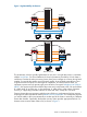
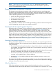
Figure 1 High Availability Architecture Node 1 fails Node 2 Node 1 pkg A mirrors pkg A pkg B pkg B mirrors Client Connections pkg A fails over to node 2 Node 2 Node 1 pkg B pkg A Client Connections This architecture, which is typically implemented on one site in a single data center, is sometimes called a local cluster. For some installations, the level of protection provided by a local cluster is insufficient.
Figure 2 Disaster Recovery Architecture Data Center A Fails pkg A Node 1 pkg B pkg C Node 3 Node 2 pkg D Node 4 Replication Link Data Center A Data Center B Client Connections packages A and B fail over to Data Center B Node 1 pkg C pkg D pkg A pkg B Node 3 Node 2 Node 4 Replication Link Data Center A Data Center B Client Connections Understanding types of disaster recovery clusters To protect against multiple points of failure, cluster components must be geographically dispersed: n
NOTE: “Metrocluster and Continentalclusters” (page 20), provides an overview of HP’s implementation of Metropolitan Cluster and Continental cluster while Chapter 3 provides an overview of Extended Distance Clusters. Disaster Recovery Architecture Guidelines The disaster recovery architectures represent a shift away from the massive central data centers and towards more distributed data processing facilities.
dictates) or store it offline in a vault. If a disaster occurs at one site, the offline copy of data is used to synchronize data at a remote site which functions in place of the failed site. Data is replicated using physical offline backup, therefore data consistency is fairly high, barring human error or an untested corrupt backup. However, data currency is compromised by the time delay in sending the tape backup to a remote site.
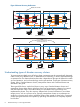
Figure 3 Physical Data Replication Physical Replication in Software Node 1 Node 2 Replication Physical Replication in Hardware Node 1 Node 2 Replication MirrorDisk/UX is an example of physical replication performed in the software; a disk I/O is written to each array connected to the node, requiring the node to make multiple disk I/Os.
• For architectures using dedicated cables, the distance between the sites is limited by the cable interconnect technology. Different technologies support different distances and provide different “data through” performance. • For architectures using common carriers, the costs can vary dramatically, and the connection can be less reliable, depending on the Service Level Agreement.
Figure 4 Logical Data Replication Node 1 Node 2 LAN Logical Replication Advantages of using logical replication are: • The distance between nodes is limited by the networking technology. • There is no additional hardware needed to perform logical replication, unless you want to boost CPU power and network bandwidth. • You can implement Logical replication to reduce risk of duplicating human error.
Using Alternative Power Sources In a high-availability environment, redundancy is applied to cluster components, such as PV links, redundant network cards, power supplies, and disks. In disaster recovery architectures another level of protection is required for these redundancies. The power supply for each data center that houses part of a disaster recovery cluster must be from a different circuit.
Figure 6 Reliability of the Network is Paramount Node 2 Node 1 Node 3 Node 4 Router Data Center A Data Center B Network uses single route Node 2 Node 1 Router Node 3 Node 4 Router Data Center A Data Center B Network uses redundant route Disaster Recovery Local Area Networking Ethernet networks is used to connect nodes in a disaster recovery architecture within the following guidelines: • Each node is connected to redundant hubs and bridges using two Ethernet host adapters.
Figure 7 Routing Highly Available Ethernet Connections in Opposite Directions Node 1 Node 3 hub From A to B bridge bridge hub Node 4 Node 2 hub bridge bridge Fr om Data Center A Data Center B C bridge hub to hub bridge A hub Node 5 Node 6 Data Center C Disaster Recovery Wide Area Networking Disaster recovery networking for continental clusters is directly tied to the data replication method.
number of transactions you process, the more bandwidth and low latency you will need. The bandwidth provided by the following connection types vary: ◦ T1 and T3: low end ◦ ISDN and DSL: medium bandwidth ◦ ATM: high end • Reliability is affected regardless of whether data replication is performed, and therefore the consistency of the data is also affected when you need to fail over to the recovery cluster.
Disaster Recovery Cluster Limitations Disaster recovery clusters have limitations, some of which can be mitigated by good planning. Some examples of MPOF that may not be covered by disaster recovery configurations: • Failure of all networks among all data centers — This can be mitigated by using a different route for all network cables.
stress levels of the site administrator to restore the data center within a short time-frame can increase the possibility of a human error in the restoration process. ◦ Automated recovery procedures and processes can be transparent to the clients. Even if recovery is automated, you may choose to, or need to recover from some types of disasters with manual recovery.
2 Metrocluster and Continentalclusters Understanding Metrocluster Metropolitan Cluster A metropolitan cluster is a cluster that has alternate nodes located in two different parts of a city or in adjacent cities. Putting nodes further apart increases the likelihood that alternate nodes will be available for failover in the event of a disaster. A Metropolitan cluster requires a third location for arbitrator nodes or a quorum server.
Figure 9 Two Data Centers and Third Location with Arbitrators Highly Available Network pkg A pkg B Node 1 Node 2 Data Center B Data Center A Node 3 pkg C Node 4 pkg D Robust Data Replication Highly Available Network Arbitrator 1 Arbitrator 2 Arbitrators Third Location Terms and Concepts Arbitration When the cluster is part of a disaster recovery solution that has nodes located in more than one data center, loss of communication can easily occur unless redundant networking is implemented with
Arbitrator Nodes Arbitrator nodes is one of the arbitration mechanisms available in Serviceguard. A network split in a four-node cluster can result in two equal-sized partitions, but in a five-node cluster it cannot. The fifth node in the cluster, acts as the arbitrator by virtue of the fact that it makes the number of nodes in the cluster odd.
Figure 10 Two Data Centers and Third Location with Arbitrators or a Quorum Server replicated data for package A PVOL --------------------------------------- SVOL replicated data for package B PVOL --------------------------------------- SVOL replicated data for package C SVOL --------------------------------------- PVOL replicated data for package D SVOL --------------------------------------- PVOL Local XP Disk Array Remote XP Disk Array PV Links A pkg A Power Circuit 1 Network Switch Node 1 C1 Nod
However, when you use two arbitrator nodes in the third location, you can place one node in one datacenter and two nodes in another datacenter. Table 1 lists the allowable number of nodes at each main data center and the third location, up to a 16-node maximum cluster size. Table 1 Supported System and Data Center Combinations (Applicable to Serviceguard Version 11.
SADTA Metrocluster provides Site Aware Disaster Tolerant Architecture (SADTA) for complex workloads such as Oracle RAC database and SAP that use CFS, CVM, or SLVM. This solution uses an additional software feature called the Site Controller Package to provide disaster recovery for workload databases. For more information on SADTA, see “Understanding Site Aware Disaster Recovery Architecture Concepts” (page 36).
Benefits of Metrocluster The following are the benefits of Metrocluster: 26 • Metrocluster offers a more resilient solution than Extended Distance Cluster, because provides full integration between Serviceguard’s application package and the data replication subsystem. The storage subsystem is queried to determine the state of the data on the arrays. In a Metrocluster configuration, application data is replicated between two data centers.
IMPORTANT: For more information on supported arrays and the features in the various releases of Metrocluster, see Disaster recovery Clusters Products Compatibility Feature Matrix . This document can be accessed at: http://www.hp.com/go/hpux-serviceguard-docs and selecting the respective Metrocluster Product.
Terms and Concepts Continentalclusters Continentalclusters is configured using two or more Serviceguard clusters. The packages in different Serviceguard clusters have a special primary-recovery relationship between them. This relation is defined by the user in Continentalclusters configuration and is enforced by the Continentalclusters software.
In addition, notifications are sent to the file /var/opt/resmon/log/cc/eventlog on the cluster node where monitoring package is running. Types of Cluster Events Cluster events are of two types in Continentalclusters, Alerts and Alarms. At least one alarm event must be triggered for the recovery process to start normally. If there are no cluster events, the recovery process cannot start in Continentalclusters. Cluster event of type alerts are typically used for informational purposes.
Figure 12 Basic configuration Recovery Group Recovery Package PRI_SCM_DB_PKG Primary Package Continentalclusters Configuration Package cconfpkg Site A Node 1 Site A Node 2 REC_SCM_DB_PKG ccmonpkg cconfpkg Site B Node 1 Site B Node 2 FC Switch FC Switch Monitor Package WAN WAN Converters Data Replication Links Site A Disk Array Site A Cluster (Primary) WAN Converters Site B Disk Array Site B Cluster (Recovery) Bi-directional / Mutual Recovery configuration In a bi-directional Continentalc
Figure 13 N-1 configuration Site B Cluster (Primary) Highly Available Network customerpkg Site A Cluster (Recovery) Node 1 Node 2 WAN ccmonpkg cust_bak sales_bak Node 1 Disk Array Disk Array Node 2 Data replication link between Site A and C salespkg Node 1 Disk Array Node 2 Site C Cluster (Primary) N-1 Bidirectional configuration N-1 bidirectional Continentalclusters configuration can have a maximum of four clusters running production application where three production clusters are recove
Cascading Failover Using Metrocluster This configuration uses three data replication groups, two of which are part of the Metrocluster and the other attached to the recovery cluster. The data centers are distributed as follows: • Primary—on the site that holds the primary copy of the data, located in the primary cluster. • Secondary—on the site that holds a remote mirror copy of the data, located in the primary cluster.
Figure 14 Cascading Failover Data Center Distribution Using Metrocluster Continentalclusters Site 3 IP Router IP Router Quorum Server App.
Integration with array based replication Continentalclusters supports array based data replication with HP P9000 or XP ,and HP P6000 or EVA with Continuous Access, HP 3PAR with Remote Copy or EMC with SRDF. Integration with software based replication Most database products have a logical replication feature to maintain a redundant copy of the database. Continentalclusters offers flexibility in terms of integrating software based replication for disaster recovery.
Site Controller support A site controller package is a container package for multiple, interdependent set of packages. The multiple, interdependent set of packages is known as a complex workload. A Continentalclusters recovery group can have a site controller package as its primary and recovery package. This helps in simplifying disaster recovery of a complex stack of applications.
that Metrocluster implements to check for data status of the application package before package start up. ◦ HP Serviceguard provides toolkits for Oracle Data Guard and IBM DB2 HADR logical replication solutions that can be used to integrate with Continentalclusters. • Oracle RAC is supported by Continentalclusters by integrating it with SGeRAC. In this configuration, multiple nodes in a single cluster can simultaneously access the database (that is, nodes in one data center can access the database).
The following are the main components of Site Aware Disaster Tolerant Architecture: • Sites • Complex Workload • Site Controller Package • Site Safety Latch Terms and Concepts Sites Site, in SADTA, is a collection of Metrocluster nodes in the same location that are connected to the same disk array. The site information must be provided in the cluster configuration file. The nodes within a site form a sub-cluster and multi-node packages can be restricted to run within this sub-cluster.
Figure 15 Root package in a complex workload SiteA_Application_package SiteB_Application_package SiteA_RAC_MNP SiteB_RAC_MNP SiteA_SG_CFS_MP SiteB_SG_CFS_MP SiteA_SG_CFS_DG SiteB_SG_CFS_DG Site A Root Packages Site B Site Controller Package Site Controller package is the container package that starts and stops a given complex workload. It also monitors the complex workload packages and also makes sure the replicated storage is in read/write state when the complex workload packages start up.
Figure 16 Web Server Configured as a Complex Workload Metrocluster Site A Apache WWW Site B Apache WWW Site Safety Latch Site A Mount Point Site A Disk Group Site A CFS Sub Cluster Site B CFS Sub Cluster SG CFS SMNP Site Controller Node 1 Site B Mount Point Site B Disk Group Site Safety Latch Node 2 Node 1 Node 2 Data Replication Disk Array Disk Array Site A Active Application Configuration Site B Passive Application Configuration Continentalclusters SADTA configuration In a Continentalcl
Figure 17 SADTA Configuration in Continentalclusters Continentalclusters Site A App. Pkg Site B App.
Support for all Metrocluster products The SADTA feature is available in all Metrocluster products. This means disaster recovery for complex workloads can be configured when using Metrocluster with Continuous Access P9000 and XP or Metrocluster with Continuous Access EVA or Metrocluster with 3PAR Remote Copy or Metrocluster with EMC SRDF. UnderstandingThree Data Center Disaster Recovery Solution A Three Data Center configuration consists of two Serviceguard clusters.
Types of Configuration Virtual Partitions or Integrity VM can be integrated with DR solutions in the following ways: 1. Monitoring and Recovering Virtualized Environments a. Virtual Partitions or Integrity VM as a Serviceguard Package in a Metrocluster. b. Virtual Partitions or Integrity VM as a Serviceguard Package in Continentalclusters. 2. Monitoring and Recovering the Application running in a Virtualized Environment. a. Virtual Partitions or Integrity VM as a Serviceguard Node in a Metrocluster. b.
Figure 19 Integrity VM or vPars as a Serviceguard Package in a Metrocluster VM DB APP Node 1 Node 2 Node 3 Node 4 Metrocluster FC Switch FC Switch Database XP Arrays Data Replication Database XP Arrays Understanding Virtualized Environments configured in Metrocluster or Continentalclusters 43
Figure 20 Integrity VM or vPars as a Serviceguard Package in Continentalclusters Continentalclusters Node 1 LAN/WAN Node 2 HPVM Pri-Pkg Node 3 Node 4 HPVM Rec-Pkg Recovery Group Primary Cluster ccmonpkg Recovery Cluster Read/Write Write Disabled Replication Link XP Arrays XP Arrays Indicates that package is running. Indicates that package is halted.
Table 2 Metrocluster dependency with NPIV (continued) Product Is NPIV Mandatory ? Metrocluster with 3PAR Remote Copy No Metrocluster with EMC SRDF Yes Virtual Partitions/Integrity VM on Separate Hosts In Figure 21, each VM host has a VM guest configured. VM guests’ Host1_VM1 and Host2_VM2 access the array on one site while Host3_VM3, and Host4_VM4 access the array on the remote site. Serviceguard cluster is configured between Host1_VM1, Host2_VM2, Host3_VM3 and Host4_VM4.
Figure 22 Multiple vPars/Integrity VM on a single Host Heartbeat Network Host1_VM1 Host2_VM2 Serviceguard Cluster Host3_VM3 Host3_VM4 Host 2 Host 1 Host 3 FC Switch FC Switch Array Replication Disk Arrays Disk Arrays Combination of Physical Hosts and Virtual Environments In Figure 23, the Serviceguard cluster is composed of both virtual HP Integrity VM guests and hosts. The cluster is configured between Host1_VM1, Host2_VM2, Host3_VM3(VM guests), and physical host4.
Figure 23 Combination of Physical Hosts and Virtual Environments Heartbeat Network Host1_VM1 Host2_VM2 Host 1 Serviceguard Cluster Host 2 Host3_VM3 Host 3 FC Switch Host 4 FC Switch Array Replication Disk Arrays Disk Arrays Understanding Virtualized Environments configured in Metrocluster or Continentalclusters 47
3 Extended Distance Cluster Configurations Extended Distance Cluster configurations (also known as Extended Campus Cluster configurations) are specialized cluster configurations, which allow a single Serviceguard cluster to extend across two or three separate data centers for increased disaster recovery. These configurations provide additional availability protection against the failure of an entire data center.
Key points that set an Extended Distance Cluster apart from a “normal” Serviceguard cluster: • It is an architecture where the cluster nodes and storage are split evenly across two different independent locations. The main purpose is to protect against failure scenarios in which one of the two locations fail entirely—as opposed to an individual node or disk failure. • There is no minimum distance between the locations.
Table 4 Extended Clusters support for HP-UX 11i v2 (continued) Product Revision Volume Manager Notes for Extended Cluster Support A.11.17 – A.11.18 VxVM 3.5, 4.1, or 5.0. Supports up to 16 nodes for distances up to 100 KM. A.11.19 VxVM 4.1 or 5.0. Supports up to 16 nodes for distances up to 100 KM. A.11.16 SLVM Supports up to 2 nodes for distances up to 100 KM. Oracle 9.2 or 10gR2. CVM 3.5 only.
Table 4 Extended Clusters support for HP-UX 11i v2 (continued) Product Revision Volume Manager Notes for Extended Cluster Support nodes for distances up to 100 KM. Oracle 9.2, 10gR2, or 11gR1. (Oracle 9.2 on Integrity servers only) 1 LVM and VxVM support in SGeRAC is the same as that provided by the equivalent Serviceguard revision. 2 LVM and VxVM support in SMS is the same as that provided by the version of Serviceguard contained in the SMS product.
Table 5 Extended Clusters support for HP-UX 11i v3 (continued) Product SMS without SGeRAC 2 SMS with SGeRAC 3 Revision Volume Manager Notes for Extended Cluster Support A.11.19 – A.11.20 ASM over raw disks RAC 10gR2, 11gR1, or 11gR2 using ASM mirroring over raw devices. This configuration is allowed by HP and supported by Oracle. Contact Oracle for ASM mirroring configuration requirements, distance limitations and number of nodes supported.
(cluster) license beyond Serviceguard is required for this solution, making it the least expensive to implement. • You may choose any storage supported by Serviceguard, and the storage can be a mix of any Serviceguard-supported storage. • This configuration may be the easiest to understand and manage because it is similar to Serviceguard in many ways • Application failover is minimized.
• CVM and CFS require link-level traffic communication (LLT) among the nodes, therefore Extended Clusters cannot be configured in Cross-Subnet configurations with CVM or CFS. As a result, only Extended Clusters using LVM volume groups are supported in Cross-Subnet configurations. • Oracle RAC requires a common subnet for the RAC interconnect between nodes, therefore Extended RAC Cross-Subnet Clusters are not supported.
• There must be less than 200 milliseconds of roundtrip latency in the link between the data centers. This latency requirement applies for both the heartbeat network and the Fiber Channel data. • Fibre Channel Direct Fabric Attach (DFA) is recommended over Fibre Channel Arbitrated loop configurations, due to the superior performance of DFA, especially as the distance increases.
package failing to startup if quorum is not present. Or, you could disable LVM quorum for the packages in the Recovery data center, and disable the automatic start of packages in the Recovery data center. In both situations, an operator can check the status of the data in the volume group in the recovery site and determine whether it is safe to proceed and start the package without LVM quorum.
Special Requirements and Recommendations for using VxVM, CVM and CFS in Extended Clusters • The Dirty Region Logging (DRL) feature is highly recommended to be used for resynchronization after a node failure. RAID-5 mirrors are not supported, because it cannot be verified that both data centers have a complete copy of all the data.
only with SG SMS A.02.00, A.02.01, or A.02.01.01. CVM/CFS 5.0.1 are available only with SG SMS A.03.00 on HP-UX 11i v3. Beginning with SG SMS A.02.01, CVM 5.0/CFS 5.0 mirroring is supported for distances of up to 100 kilometers for 2, 4, 6, 8, 10, 12, 14, or 16 node clusters on HP-UX 11i v2 or 11i v3. Standalone CVM 5.0 (without SG SMS) is also supported.
it is suggested to tune the buffer credits properly for the ISL used for data replication between the data centers. • If CVM or CFS is being used and all data replication links are lost between the data centers, but the network links remain functional, it is likely that all mirror copies that the CVM master cannot contact will be detached from the disk group.
Common SONET or SDH Links for both TCP/IP Networking and Fibre Channel Data • For this document, Synchronous Optical Network (SONET) an ANSI standard, and Synchronous Digital Hierarchy (SDH) an ITU T standard, can be considered to be roughly equivalent and interchangeable. For brevity, this document refers only to SONET, however applies equally to SDH. SONET can support a point to point or a ring topology.
Extended Distance Cluster with two Data Centers Configurations with two data centers have the following additional requirements: • To maintain cluster quorum after the loss of an entire data center, you must configure dual cluster lock disks (one in each data center). Cluster lock disks are supported for up to four nodes, the cluster can contain only two or four nodes. Serviceguard does not support dual lock LUNs, so lock LUNs cannot be used in this configuration.
contains a single node, only one Arbitrator node is allowed. Cluster lock disks are not supported in this configuration. Arbitrator nodes are not supported if CVM or CFS is used in the cluster. • If a Quorum Server node is used, there must be an equal number or nodes (1–8) in each Primary data center. The third location can contain a single Serviceguard Quorum Server node (running HP-UX or Linux), with a separate power circuit.
Figure 25 Extended Distance Cluster with Two Data Centers Network Switch Network Switch Network Switch Node A Heartbeat Networks over FDDI Network Switch Node B Node C FC Switch Fibre Links For Software Mirroring Data Replication Node D FC Switch FC Switch FC Switch Cluster Lock Storage Site 1 Cluster Lock Maximum distance 50 kilometers Storage Site 2 In the Figure 25 (page 63) Finisar (long haul) GBICs and cabling that supports up to 80 kilometers are used for the ISL links between the F
Figure 26 Extended Distance Cluster with Two Data Centers and DWDM Network Switch Network Switch DWDM Node A Node B DWDM Cluster Heartbeat Network and Storage Connections Data replication is being done with MirrorDisk/UX FC Switch Network Switch Network Switch DWDM DWDM Node C Node D FC Switch FC Switch FC Switch Cluster Lock Cluster Lock Maximum distance 100 kilometers Storage Site 1 Storage Site 2 In the Figure 26 (page 64), the alternate paths for both networking and Fibre Channel
Figure 27 Extended Distance Cluster Configuration with Two Data Centers and a Third Location with DWDM Links Arbitrator Third location Node E Node F Network Switch Network Switch DWDM e anc Dist um eters xim m Ma 0 kilo 10 Network Switch Network Switch Maxim um 100 kil Distance omete rs DWDM DWDM Node A Node B DWDM Network Switch Network Switch DWDM Redundant DWDM FC Switch DWDM Node C Node D FC Switch FC Switch FC Switch Storage Storage Primary Data Center 1 Maximum distance 100 kil
You can use SONET instead of DWDM in this configuration by replacing the DWDM boxes with SONET boxes. With SONET, you can use a point to point topology, as is shown in this example, or you can use a dual SONET ring topology which passes through all three data centers, where the working ring and the protection ring are alternately routed.
(and 10, 12, 14, or 16 with CVM 5.0 or 5.0.1 and Serviceguard A.11.19, SG SMS A.02.01, A.02.01.01 ,or SG SMS A.03.00) in this cluster if CVM or CFS is used and the distance is 10 kilometers or less. There can be only two nodes in this cluster, if CVM or CFS 4.1 is used and the distance is between 10 and 100 kilometers. There can be 2 or 4 nodes in this cluster, if CVM or CFS 5.0 or 5.0.1 is used and the distance is between 10 and 100 kilometers.
Figure 29 Extended Cross-Subnet Cluster with Two Data Centers and a Third Location with WDM Links QS Node Quorum Server Data Center Network Switch 1 Network Switch 3 Network Switch 2 Router 2 Network Switch 4 Router 3 WAN Router 1 Router 4 Cross Subnet Configuration DWDM Node A Node B FC Switch DWDM Storage Connections Redundant WDM Links frequently Node C Node D FC Switch FC Switch FC Switch Storage Primary Data Center 1 Maximum distance 100 kilometers Storage Primary Data Center 2
Metrocluster product is suggested) . There can be up to 16 nodes in this cluster and the maximum distance supported is 100 kilometers. You can use SONET instead of WDM in this configuration. With SONET, you could use a point to point topology, as shown in this example, or you can use a dual SONET ring topology which passes through the two Primary data centers, where the working ring and the protection ring are alternately routed.
4 Comparison of Disaster Recovery Solutions Table 7 summarizes and compares the disaster recovery solutions that are currently available: Table 7 Comparison of disaster recovery Cluster Solutions Attributes Extended Distance Cluster Extended Distance Cluster Metrocluster for RAC Continentalclusters Key Benefit Excellent in “normal” operations, and partial failure.
Table 7 Comparison of disaster recovery Cluster Solutions (continued) Attributes Application Failover Extended Distance Cluster Extended Distance Cluster Metrocluster for RAC Continentalclusters re-sync is required in many scenarios that have subsystem, so the host many scenarios that multiple failures). does not experience a have multiple failures.) performance hit. Incremental re-syncs are done, based on bitmap, minimizing the need for full re-syncs.
Table 7 Comparison of disaster recovery Cluster Solutions (continued) Attributes Extended Distance Cluster Extended Distance Cluster Metrocluster for RAC Continentalclusters Continuous Access over IP (pre-integrated solution) Continuous Access over ATM (pre-integrated solution) Cluster Network Cross Subnet for all cluster notes if the Cross Subnet feature is not used or not available. Single IP subnet Single IP Subnet (requires a common subnet for all cluster nodes), except for Cross-Subnet clusters.
Differences Between Extended Distance Cluster and Metrocluster The major differences between an Extended Distance Cluster and a Metrocluster are: • The methods used to replicate data between the storage devices in the two data centers. The two basic methods available for replicating data between the data centers for HP-UX clusters are either host-based or storage array-based. Extended Distance Cluster always uses host-based replication (either MirrorDisk/UX or Veritas VxVM mirroring).
Glossary A application restart Starting an application, usually on another node, after a failure. Application can be restarted manually, which may be necessary if data must be resynchronized before the application can run (example: Business Recovery Services work like this.) Applications can be restarted by an operator using a script, which can reduce human error. Or applications can be started on the local or remote site automatically after detecting the failure of the primary site.
cluster alert Time at which a message is sent indicating a problem with the cluster. cluster event A cluster condition that occurs when the cluster goes down or enters an unknown state, or when the monitor software returns an error. This event may cause an alert message to be sent out, or it may cause an alarm condition to be set, which allows the administrator on the Recovery Cluster to issue the cmrecovercl command.
disaster recovery architecture A cluster architecture that protects against multiple points of failure or a single catastrophic failure that affects many components by locating parts of the cluster at a remote site and by providing data replication to the remote site. Other components of disaster recovery architecture include redundant links, either for networking or data replication, that are installed along different routes, and automation of most or all of the recovery process.
M M by N A type of Symmetrix grouping in which up to two Symmetrix frames may be configured on either side of a data replication link in a Metrocluster with EMC SRDF configuration. M by N configurations include 1 by 2, 2 by 1, and 2 by 2. manual failover Failover requiring human intervention to start an application or service on another node. Metrocluster A Hewlett-Packard product that allows a customer to configure an Serviceguard cluster as a disaster recovery metropolitan cluster.
physical data replication An online data replication method that duplicates I/O writes to another disk on a physical block basis. Physical replication can be hardware-based where data is replicated between disks over a dedicated link (for example EMC’s Symmetrix Remote Data Facility or the HP Storage Disk Array XP Series Continuous Access), or software-based where data is replicated on multiple disks using dedicated software on the primary node (for example, MirrorDisk/UX).
• multiple power cords • online addition or replacement of I/O cards, memory special device file The device file name that the HP-UX operating system gives to a single connection to a node, in the format /dev/devtype/filename. split-brain syndrome When a cluster reforms with equal numbers of nodes at each site, and each half of the cluster thinks it is the authority and starts up the same set of applications, and tries to modify the same data, resulting in data corruption.
Index A O asynchronous data replication, 10 offline data replication, 9 online data replication, 10 operations staff general guidelines, 19 C cluster extended distance, 48, 52, 53 cluster maintenance, 19 configuring, 15 disaster recovery Ethernet networks, 15 disaster recovery WAN, 16 consistency of data, 9 currency of data, 9 D data center, 7 data consistency, 9 data currency, 9 data recoverability, 9 data replication, 9 ideal, 13 logical, 12 offline, 9 online, 10 physical, 10 synchronous or asynchron