HP XP7 Continuous Access Synchronous for Mainframe Systems User Guide Abstract Continuous Access Synchronous Z helps you create and maintain a synchronous backup of critical data in a remote location. This document describes and provides instructions for planning, configuring, and maintaining a Continuous Access Synchronous Z system on HP XP7 Storage.
© Copyright 2014 Hewlett-Packard Development Company, L.P. Confidential computer software. Valid license from HP required for possession, use or copying. Consistent with FAR 12.211 and 12.212, Commercial Computer Software, Computer Software Documentation, and Technical Data for Commercial Items are licensed to the U.S. Government under vendor's standard commercial license. The information contained herein is subject to change without notice.
Contents 1 Continuous Access Synchronous Z overview...................................................8 How Continuous Access Synchronous Z works .............................................................................8 Typical components .................................................................................................................9 Storage systems .......................................................................................................................9 Volume pairs ...
Maximum number of pairs supported...................................................................................37 Calculating maximum number of pairs.............................................................................37 Priority for initial copy operations and scheduling order..........................................................38 Example 1: more initial copies than previously specified.....................................................
Resynchronizing pairs.............................................................................................................70 Deleting pairs........................................................................................................................72 7 Monitoring and maintaining the Cnt Ac-S Z system.......................................74 Monitoring pair status, license capacity.....................................................................................
Resynchronization fails due to shortage of host resources.......................................................114 Cache failure, unregistered TPC-R error ..............................................................................114 Pinned track recovery............................................................................................................114 11 Support and other resources...................................................................115 Contacting HP..........................
Confirm window..............................................................................................................158 Edit SCP Time wizard............................................................................................................159 Edit SCP Time window......................................................................................................159 Change SCP Time window................................................................................................
1 Continuous Access Synchronous Z overview A Continuous Access Synchronous Z system creates and maintains a mirror image of a production volume at a remote location. Data in a Continuous Access Synchronous Z backup stays synchronized with the data in the primary XP7 Storage storage system. This happens when data is written from the host to the primary storage system then to the secondary storage system, via the Fibre Channel data path.
Typical components A typical configuration consists of the following components. Many but not all require user setup. • The primary XP7 storage system is connected to a host. The secondary storage system is connected to the primary system via Fibre Channel data paths. The secondary system may be XP7 or other HP model. • A host at the local site, connected to the primary storage system.
The primary system communicates with the secondary system over dedicated Fibre Channel data paths. The XP7 CU can function simultaneously as a primary system for one or more P-VOLs, and as a secondary system for one or more S-VOLs. This kind of configuration requires that data paths and Fibre Channel ports are configured for both copy directions. Volume pairs As described previously, original data is stored in the P-VOL and the remote copy is stored in the S-VOL.
system. RAID Manager provides a full scripting capability that can be used to automate replication operations. • Business Continuity Manager (BCM), which is a command line interface from which pair operations are run and pair status is monitored. BCM commands are issued from the host to the storage system. • PPRC, with which most operations can be performed from the host. All XP7 storage systems support IBM PPRC host software functions.
• Initial Copy Priority. You specify the order in which copying is performed on multiple pairs. This is used if more pairs are being created in the operations than the maximum initial copy activity setting. • Round Trip Time. You specify the time limit for data to travel from P-VOL to S-VOL. The value is used by the storage system to control initial copy pace when update copying is in progress. These options are available on Remote Web Console. Copy pace is also available using RAID Manager.
2 Requirements and specifications This chapter provides basic system requirements, along with specifications for BCM, PPRC, and other mainframe-related interfaces and functions. In addition to the information here, “Planning for Continuous Access Synchronous Z” (page 28) provides many specifications, recommendations, and restrictions for the elements of a Continuous Access Synchronous Z system that require attention before setting up and using Continuous Access Synchronous Z.
Item Requirement Mainframe related • IBM PPRC is supported. • Optional error report communications (ERC) function requires MVS/DFP 3.2.0 or later. • If the S-VOL is associated with a Cnt Ac-J Z P-VOL, and the primary or secondary systems consist of several CPU complexes, a SYSPLEX timer is required to provide a common time reference for the host I/O time-stamping function. • ICKDSF R16 + PTF functions require VM/ESA 2.1.0 or later. Contact your HP account team for the latest information.
Item Requirement Error Reporting Communications (ERC) software • Required for disaster recovery. • Recommended for data migration. See “Error reporting communications” (page 46) for more information. Interfaces • Remote Web Console is required. ◦ The following RWC roles are required to operate: - Storage Administrator (Remote Copy) - Storage Administrator (System Resource Management) - Storage Administrator (Provisioning) ◦ The primary system must be LAN-attached to a Remote Web Console computer.
Operation RCU registration—YKBLDPTH5 Option Default value used by BCM CFW Data S-VOL1 RCU options Minimum Paths 1 RIO MIH Time 15 seconds FREEZE Disabled Round Trip Time 1ms CU options PPRC support Cnt Ac-S Z service SIM No Not Report 1. 2. 3. 4. To change options, see “Changing P-VOL Fence Level, CFW Data” (page 82). The initial copy operation follows the YKMAKE execution order. See “Priority for initial copy operations and scheduling order” (page 38).
The following table shows the conditions when the F/M=FB message is output (Yes) or stopped (No).
RCU registration (CESTPATH) • RCU options. If CESTPATH is used to create a path, the following default values are used: ◦ Minimum Paths = 1 ◦ RIO MIH Time = 15 sec ◦ Round Trip Time = 1 ms The CGROUP option of the CESTPATH command applies to the FREEZE option. • CU options.
PPRC command Parameter BCM command PACE config (CopyPace) CRIT config (ErrorLevel) MSGREQ Not supported ONLINSEC CSUSPEND CDELPAIR Support type DEVN Not supported *1 YKSUSPND config PRIM config SEC config PRIMARY Not supported QUIESCE Not supported DEVN YKDELETE config YKRECOVER config YKQUERY config PRIM SEC CRECOVER DEVN PRIM SEC ID CQUERY DEVN CGROUP FORMAT or UNFORMAT Not supported VOLUME/PATHS Not supported DEVN CDELPATH YKFREEZE or YKRUN config PRIM config
SAID values for PATH LINK (CL1) Packg local Port SAID Packg local Port SAID Packg local 1PC SAID Packg local CL1-A X'0000' 1PJ CL1-J X'0008' CL3-A X'0020' (Basic) X'0080' X'00C0' 1PG CL9-J (Option) CLB-J (DKA10 Basic) CLD-J X'0088' X'0048' 1PA CL9-A (Option) CLB-A (DKA00 Basic) CLD-A CL3-J X'0028' CL5-A X'0040' CL5-J CL7-A X'0060' CL7-J X'0068' CLF-A X'00E0' CLF-J X'00E8' CL1-B X'0001' CL1-K X'0009' CL9-B X'0081' CL9-K X'0089' CL3-B X'0021' CL3-K X'0029' CLB-
SAID Values for PATH LINK (CL2) Packg local Port SAID Packg local Port SAID Packg local 2PC SAID Packg local CL2-A X'0010' 2PJ CL2-J X'0018' CL4-A X'0030' (Basic) X'0090' X'00D0' 2PG CLA-J (Option) CLC-J (DKA12 Basic) CLE-J X'0098' X'0058' 2PA CLA-A (Option) CLC-A (DKA02 Basic) CLE-A CL4-J X'0038' CL6-A X'0050' CL6-J CL8-A X'0070' CL8-J X'0078' CLG-A X'00F0' CLG-J X'00F8' CL2-B X'0011' CL2-K X'0019' CLA-B X'0091' CLA-K X'0099' CL4-B X'0031' CL4-K X'0039' CLC-
without interrupting access to the data. See the following IBM publications for important information about the requirements and procedures for P/DAS operations: Planning for IBM Remote Copy (SG24-2595), Advanced Copy Services (SC35-0355), DFSMS MVS V1 Remote Copy Guide and Reference (SC35-0169). Restrictions The following restrictions apply to P/DAS use with Continuous Access Synchronous Z: • P/DAS through channel extenders is not supported. • P/DAS does not support CFW operations.
SAID values for link path statistical information (CL1) Packg local Port SAID 1PC SAID Packg local CL1-A X'0040' X'0042' 1PG CL9-J (Option) CLB-J (DKA10 Basic) CLD-J X'0060' X'0022' 1PA CL9-A (Option) CLB-A (DKA00 Basic) CLD-A CL7-J X'0023' CLF-A X'0043' CLF-J X'0063' X'0004' CL1-K X'0024' CL9-B X'0044' CL9-K X'0064' CL3-B X'0005' CL3-K X'0025' CLB-B X'0045' CLB-K X'0065' CL5-B X'0006' CL5-K X'0026' CLD-B X'0046' CLD-K X'0066' CL7-B X'0007' CL7-K X'0027' CLF-B
SAID values for link path statistical information (REAR CL2) Packg local Port SAID Packg local Port SAID Packg local Port SAID Packg local Port SAID 2PC CL2-A X'0080' 2PJ CL2-J X'00a0' X'00c0' X'00e0' X'0081' CL4-J X'00a1' CLC-A X'00c1' 2PG (Option) CLA-J CL4-A 2PA (Option) CLA-A (Basic) CLC-J X'00e1' CL6-A X'0082' CL6-J X'00a2' CLE-A X'00c2' CLE-J X'00e2' CL8-A X'0083' CL8-J X'00a3' CLG-A X'00c3' CLG-J X'00e3' CL2-B X'0084' CL2-K X'00a4' CLA-B X'00c4'
Requirements • System option mode 114 set to OFF. • System option mode 484 and 769 set to ON. • A bi-directional path between MCU and RCU must be in place. Recommendations • For best performance, the maximum number of pairs for the Basic HyperSwap function is 1,000 per CHA. • The MIH value of host I/O and the host operation is about one second. This allows MIH to be reported for host I/O or for the host operation. • Resources in the host system must be adequate.
To enable data migration from existing storage to the EAV (3390-A), you can combine a non-EAV (3390-X) as the P-VOL and an EAV (3390-A) as the S-VOL. However, a reversed combination in which EAV (3390-A) is the P-VOL and non-EAV (3390-X) is the S-VOL is not supported. NOTE: You can use data migration from an earlier storage model P-VOL to an EAV S-VOL.
Category Path RWC operation type Option Edit Pair Options (no option) No Add Remote Connection (no option) Yes Operation Others RAID Manager support Minimum Paths No (fixed to 1) RIO MIH Time (sec) No (fixed to 15 (sec.
3 Planning for Continuous Access Synchronous Z This chapter provides information and instructions for planning primary and secondary system, pair volumes, data paths, and other elements. Storage system preparation The following preparations are required for the storage systems in a Continuous Access Synchronous Z pair relationship. • You can pair the volumes on XP7 Storage with volumes on another XP7, P9500, or XP24000/XP20000 Disk Array.
NOTE: Neither cache nor shared memory can be added to or removed from the storage system when pair status is Pending. When either of these tasks is to be performed, first split any pairs in Pending status; then resynchronize the pairs when the cache or shared memory operation is completed. DASD fast write requirements DASD fast write (DFW) is required at the primary and secondary system only when Required is specified for the PPRC DFW to S-VOL option.
Option mode Description 114 Allows dynamic port mode setting (Initiator/RCU target for Fibre Channel) through PPRC CESTPATH and CDELPATH commands: • ON: Initiator ports automatically change to RCU target ports, or vice versa. • OFF (default): Initiator ports do not change to RCU target ports, or vice versa. For Fibre Channel interface, do not use the CESTPATH and CDELPATH commands at the same time as the SCSI path definition function of LUN Manager.
System performance considerations Synchronous copy operations affect I/O performance on the host and on the primary and secondary systems. Continuous Access Synchronous Z provides options for minimizing the impact and for maximizing the efficiency and speed of copy operations for the best level of backup data integrity.
The following table shows the initial copy pace used for the response time calculation.
Check with your HP service provider for more information. • • Analyze write-workload. Bottlenecks severely impact performance, but the workload data you collect (MB/s and IOPS) help determine the following key elements that, when sized properly, form a data path that operates free of bottlenecks under all workload levels: ◦ Amount of bandwidth. ◦ Number of data paths. ◦ Number of host-interface paths.
Planning pairs and pair volumes This section discusses requirements, options, and settings you need for setting up pairs and pair volumes. You begin by: • Identifying data and volumes at the local site that you want to protect with a backup • Setting up volumes at the remote site that will hold copied data. The following helps ensure that the pairs you create fit your requirements.
copy operation if the track format for both the P-VOL and S-VOL does not meet the following requirements: ◦ The P-VOL and S-VOL must have the same track format. ◦ Record zero (R0) must be standard format, with key length of zero and data length of eight. The primary system will abort the initial copy operation if R0 is not standard format. ◦ The CCHH (logical cylinder address and logical head address) of R0 must be identical to the physical cylinder address and physical head address of the track.
If the volumes that become S-VOLs are physically attached to the same system images as the volumes that become the P-VOLs, the following error-prone situations may occur: • When a pair is established using the TSO CESTPAIR command, the secondary system might be online (PPRC allows this; Continuous Access Synchronous Z does not). This could produce a duplex secondary online to a host image, the results of which are not predictable. • When a pair is released, the old S-VOL is usually offline.
and the system will keep track of updates to the P-VOL. This allows the pair to be resynchronized quickly. This setting also reduces the amount of time required to analyze S-VOL consistency during disaster recovery. This setting is functionally equivalent to the CRIT(YES PATHS) parameter for the CESTPAIR command. • Never – the P-VOL is never fenced. This setting should be used when I/O performance out-weighs data recovery.
2. Calculate the number of bitmap areas per volume. In the following calculation, differential data is measured in bits. 122,752 bits is the amount of differential data per bitmap area. Number of bitmap areas = ceil ( (Number of cylinders x 15) / 122,752) NOTE: Doing this calculation for multiple volumes can result in inaccuracies. Perform the calculation for each volume seperately, then total the bitmap areas. The following examples show correct and incorrect calculations.
Example 1: more initial copies than previously specified In this example, four initial copies are being created in the same operation, but Maximum Initial Copy Activities is set at 2. In this scenario, the Priority field in the Create Pairs window would be set as shown in the following table. P-VOL Value set for Priority LDEV 00 2 LDEV 01 3 LDEV 02 1 LDEV 03 4 The order for the initial copy and the Priority for the P-VOLs are shown in the following table.
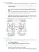
Priority is determined within the range of the number of initial copy operations performed at the same time. Therefore, until the first initial copy operations complying with the order set by Priority are completed, the additional initial copy operations are not started. Consistency group planning Consistency groups allow you to perform one operation on all pairs in the group. Consistency groups also ensure that all pairs are managed in a consistent status.
Figure notes: • RAID Manager manages the consistency group on all primary and secondary system. Business Continuity Manager cannot be used with multiple systems. • Open and mainframe primary volumes (P-VOLs/P-VOLs) receive I/O requests from their applications at the primary (main) site, and data in the volumes is updated. • Continuous Access Synchronous or Continuous Access Synchronous Z runs the copy operation in the consistency group.
• If you use BCM to resynchronize a Cnt Ac-S Z pair in an open/mainframe consistency group with one primary and secondary system, all pairs in the consistency group are resynchronized. Even if a Cnt Ac-S S-VOL is being accessed by a host, the pair is nevertheless resynchronized with the others. Make sure to check the status of all pairs in the consistency group before resynchronizing.
Procedure 2 To assign new pairs to a new consistency group 1. 2. Create RAID Manager configuration definition file C for a multiple primary and secondary system configuration. Perform the paircreate operation according to configuration definition file C created in Step 1. Procedure 3 To assign existing pairs to a new consistency group 1. 2. 3. 4. 5. 6. Create RAID Manager configuration definition file A with which to use RAID Manager for pair operations.
Split behaviors for pairs in a CG When the pairs in a consistency group receive updates while in the process of being split or suspended, or when they are about to be split or suspended, S-VOL data consistency is managed as follows: • If I/O processing is in progress on pairs in the same consistency group, and the split or suspend operation begins, the I/O processing completes first, then the split/suspend operation is run.
In such a case, resynchronize the consistency group and then run the split command again. Host access after split You can specify settings for read/write access to the P-VOL/P-VOL and S-VOL/S-VOL in consistency groups after pairs are split. These settings are specified using RAID Manager or Business Continuity Manager. • The RAID Manager settings for Cnt Ac-S are optional. • The Business Continuity Manager settings for Cnt Ac-S Z are required.
Pair statuses All = PSUS Cnt Ac-S Z pairs All = Duplex Some = Duplex, some = Suspend All = Suspend Cnt Ac-S Z: Suspend Cnt Ac-S Z: Suspend Cnt Ac-S Z: Suspend Cnt Ac-S: PSUS Cnt Ac-S: PSUS Cnt Ac-S: PSUS Cnt Ac-S Z: Cnt Ac-S Z: Cnt Ac-S Z: Suspend - RAID Manager: Duplex - RAID Manager: Duplex/Suspend - BCM: Suspend - BCM: Suspend Error reporting communications Error reporting communications (ERC) transfers information between host processors at the local and remote sites.
• For distances from 1.5 km to 10 km, (4,920 feet to 6.2miles) single mode longwave optical fibre cables are required. • For distances from 10 km to 30 km (6.2 to 18.6 miles), single-mode longwave Fibre Channel interface cables with up to two switches are required. • For distances greater than 30 km, approved third-party channel extender products and telecommunications lines are required. Continuous Access Synchronous Z operations typically do not extend past 30 km.
• • Set port topology to the following: ◦ NL port: Fab on, FC-AL ◦ N port: Fab on, Point-to-Point ◦ Some switch vendors require F port (for example, McData ED5000). Host I/O response time can be improved on long distance switch connections by using host mode options 49 and 50, or 51. The following table describes these options for the 16FC8 package. A HP-approved channel extender is required.
• When 4,000 pairs or more are used, we recommend that you restrict the number of pairs when creating pairs, so that 4,000 pairs or less use one physical path, to distribute load on the physical path. • When you set up remote-to-local data paths, specify the same path group ID as specified for the local-to-remote paths. • You can reverse the local-to-remote data path to the remote-to-local direction using the PPRC TSO CESTPATH and CDELPATH commands and system option mode 114.
4 Sharing Continuous Access Synchronous Z volumes This chapter helps you plan Continuous Access Synchronous Z (Cnt Ac-S Z) pair volumes when they are shared with non-Cnt Ac-S Z volumes. All the software products that can be used with Cnt Ac-S Z are discussed here. Volume types that can be shared with Continuous Access Synchronous Z The following table shows when volumes used by other software can also be used as Cnt Ac-S Z P-VOLs and S-VOLs.
Functions and volumes Used as P-VOL? Used as S-VOL? P-VOL (primary system) in Pending status No No P-VOL in Duplex status Yes No. The volume can be used as an S-VOL only when you restore a Cnt Ac-S Z pair or perform a BCM YKRESYNC REVERSE operation. P-VOL in Suspend status Yes No. The volume can be used as S-VOL only when you restore a Cnt Ac-S Z pair or perform a BCM YKRESYNC REVERSE operation. P-VOL suspended due to a failure Yes No.
Functions and volumes Used as P-VOL? Used as S-VOL? Volume registered in a security group Yes Yes. If the volume is disabled for use as S-VOL, the volume cannot be used as S-VOL. 1. The volume performs differently according to the type of difference management. 2. For more information, contact the HP Technical Support. 3. If you use Cnt Ac-S Z with Compatible FlashCopy, the Cnt Ac-S Z pairs must be created without using the consistency groups. 4.
Provisioning Z automatically releases pages with reclaiming zero pages in the THP V-VOL, thus increasing usable capacity. Pages that include control cylinder information are not released (see next). ◦ If a pair does not include a THP V-VOL, volume capacity is counted toward Cnt Ac-S Z license capacity. If a pair includes a THP V-VOL, only the allocated page capacity of volume capacity is counted toward Cnt Ac-S Z license capacity.
Performance Monitor Performance Monitor software provides detailed information about I/O activity and hardware performance in XP7 systems. Storage system usage and performance data is collected and displayed by Performance Monitor. This information helps you to: • Identify the optimum timing for performing Cnt Ac-S Z operations. • Determine the best locations for the Cnt Ac-S Z S-VOL (for example, parity groups with less-frequently accessed volumes to avoid bottlenecks of backend activity).
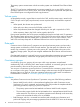
Figure 2 Shared Cnt Ac-S Z P-VOL with BC Z P-VOL • In the following figure, the Cnt Ac-S Z S-VOL also functions as an BC Z P-VOL. In this configuration, BC Z provides another (or several more) backup copies of a Cnt Ac-S Z P-VOL. When a BC Z P-VOL is shared with the Cnt Ac-S Z S-VOL, the write operation to the Cnt Ac-S Z P-VOL takes a longer time than normal. This is especially true when the BC Z pair is in the V-Split/SUSPVS status and is caused by the BC Z copying process.
Status reporting and data currency The following table shows the pair status that is reported for different combinations of shared volumes. Number of Cnt Ac-S Z pairs Number of BC Z S-VOLs Pair status 0 0 Simplex 0 1 BC Z pair status 0 2 or more BC Z pair status for the S-VOL with lowest LDEV ID 1 0 Cnt Ac-S Z pair status 1 1 Cnt Ac-S Z pair status 1 2 or more Cnt Ac-S Z pair status • Cnt Ac-S Z pair status is reported to the host if you query the Cnt Ac-S Z P-VOL or S-VOL.
Virtual LVI Virtual LVI volumes can be assigned to Cnt Ac-S Z pairs, with the following restrictions: • The S-VOL must have the same capacity as the P-VOL. • When performing Virtual LVI operations on an existing Cnt Ac-S Z P-VOL or S-VOL, you must release the pair first to return the volume to Simplex status. For more information, see thehe HP XP7 Provisioning for Mainframe Systems User Guide. Auto LUN The following table shows when Cnt Ac-S Z volumes may be used as Auto LUN volumes.
Enabled Read Only Disabled Enabled Disabled 58 P-VOL/S-VOL Pairs cannot P-VOL/S-VOL Pairs cannot Pairs cannot Pairs cannot Read only be created Read only be created be created be created P-VOL Read only, S-VOL Read/Write enabled Protect P-VOL Read only, S-VOL Read/Write enabled P-VOL/S-VOL P-VOL/S-VOL Pairs cannot Pairs cannot Read only Read only be created be created Pairs cannot Pairs cannot Pairs cannot Pairs cannot Pairs cannot Pairs cannot be created be created be created be created be created
5 Cnt Ac-S Z configuration This chapter provides instructions for configuring Continuous Access Synchronous Z. Configuration workflow You must have Storage Administrator (Remote Copy) role to perform most Continuous Access Synchronous Z operations using Remote Web Console. Configuration consists of the following operations: • Check prerequisites for each procedure. • See “Planning pairs and pair volumes” (page 34). • On the primary and secondary system, install the data paths.
Procedure 7 To define port attributes 1. 2. 3. 4. In the Storage Systems tree, click Ports/Host Groups. In the Ports/Host Groups window, click the Ports tab and select the port to be changed. From the Actions menu, click Ports/Host Groups > Edit Ports. In the Edit Ports window, select a Port Attribute: Initiator or RCU Target. For all other settings, see the HP XP7 Provisioning for Mainframe Systems User Guide. 5. 6. 7. Click Finish.
• The secondary system serial number, LDKC, controller ID, and port numbers are required. The secondary SSID may also be required. NOTE: When using RAID Manager (including Raidcom), the XP7 serial number requires a prefix of "3". • One of the fields, Round Trip Time, is covered extensively in “Determining Round Trip Time” (page 31). • Another field, Minimum Number of Paths, is also covered in more detail in “Determining Minimum Number of Remote Paths” (page 32).
1. 2. For Model, select the storage system model and number. For Serial Number, enter one of the following secondary system serial numbers. - XP7: 1 to 99999 (5 digits) - P9500 or XP24000/XP20000 Disk Array: 1 to 99999 (5 digits) - HUS VM: 200001 to 265535 (6 digits) 3. 4. For Remote CU, select the secondary system’s CU number in a range from 00 to FE. For SSID, select the secondary system’s SSID. The range is from 0004 to FFFE. If two or more valid SSIDs display, the - button is available.
2. 3. From the Actions menu, click Remote Replication > Edit Remote Replica Options. In the Edit Remote Replica Options window, for Copy Type, select TC/TCMF. 4. Change Storage System Options as needed. Settings apply to the storage system. Setting # of vols.
1. For Maximum Initial Copy Activities, specify the number of volumes to be copied concurrently per initial copy operation. The range is from 1 to 512 volumes; 64 is the default. Note the following: - This setting may impact performance on the primary system. This depends on the number you specify and the amount of I/O activity. The default may or may not limit the impact on performance, depending on your number of data paths, pairs, and so on. You should consider these factors when making a selection.
Changing SCP time SCP (state change pending) time is the interval that I/O from the host is suspended. Because SCP time is shared between Continuous Access Synchronous Z and Compatible FlashCopy, make sure to take into account the amount of time required by both products when setting the value. Procedure 10 To specify or change SCP time 1. 2. 3. In the Storage Systems tree, click Replications. From the Actions menu, click Remote Replication > Edit SCP Time.
6 Cnt Ac-S Z pair operations This chapter provides instructions for performing Continuous Access Synchronous Z pair operations. Pair operations workflow You must have Storage Administrator (Remote Copy) role to perform Continuous Access Synchronous Z operations. Basic Continuous Access Synchronous Z operations consist of the following operations. • Check prerequisites for each procedure. • Always check pair status.
• During this operation, you can specify multiple P-VOLs to be paired, but only one S-VOL. In order to plan how the system assigns subsequent S-VOLs, see the bullet, “When creating multiple pairs concurrently....” in “Pair volume requirements and recommendations” (page 34). • During this operation, you can specify whether to fence the P-VOL when an error occurs. This is discussed in detail in “Allowing I/O to the P-VOL after a split—Fence Level options” (page 36) .
1. For Base Secondary Volume, select the initial S-VOL’s CU number and LDEV number. If you are selecting only one P-VOL, this LDEV is the secondary volume. If you select multiple P-VOLs for pairing, this LDEV is the base S-VOL that is assigned to the first P-VOL and from which subsequent S-VOL LDEVs are assigned to the list of P-VOLs. CAUTION: In XP24000/XP20000 Disk Array and P9500, LUN IDs display in hexadecimal numbers. In XP7, LUN IDs display in decimal or hexadecimal numbers.
track of which pairs have the DFW required setting, and make sure that DFW to the S-VOL is not blocked. If a Cnt Ac-S Z pair is established using PPRC commands, the DFW to S-VOL option is set to the DFW not required setting. 7. 9. For Host I/O Time Stamp Transfer, specify whether the host I/O time stamp is transferred from P-VOL to S-VOL. Enable transfers, Disable does not transfer; Disable is the default.
5. For Primary Volume Write, specify whether writing to the P-VOL is enabled while the pair is split. • Depend on Primary Volume Fence Level: Writing to the P-VOL is based on fence level specified during the Create Pairs operation. This is the default. • Disable: Write I/Os to the P-VOL are rejected regardless of the fence level. Select this option to maintain synchronization of the P-VOL and S-VOL. Do not select this option if the P-VOL is necessary for host system operations.
Procedure 13 To resynchronize one or more pairs 1. 2. 3. 4. 5. In the Storage Systems tree, click Replications > Remote Replications. In the Remote Replications window, click the Cnt Ac-S Pairs tab, then select the pair to be resynchronized. From the Actions menu, click Remote Replications > Resync Pairs. In the Resync Pairs window, ensure that the pair to be resynchronized appears in the Selected Pairs table.
Deleting pairs A Continuous Access Synchronous Z pair can be deleted. Doing this deletes the Cnt Ac-S Z relationship, though not the volumes or their data. • When it is no longer necessary to maintain a remote copy of the P-VOL, delete a pair from the primary system only. All update operations are stopped and pair status for both the P-VOL and S-VOL changes to unpaired. When a pair is deleted, the primary system continues to accept write I/O to the former P-VOL but does not keep track of the updates.
5. 6. 7. 8. For Delete Mode, specify one of the following: • Normal: Deletes the pair only if the primary system can change both P-VOL and S-VOL to unpaired volumes. • Force: Forcibly deletes pairs even when the primary system cannot communicate with the secondary system. Force allows host operations to continue. • Force (All pairs in the same remote connections): Deletes forcibly all pairs using the same remote connection. Click Finish.
7 Monitoring and maintaining the Cnt Ac-S Z system This chapter provides information and instructions for monitoring and maintaining a Continuous Access Synchronous Z system. Monitoring pair status, license capacity Monitoring the Continuous Access Synchronous Z system is an ongoing operation that should be performed frequently to keep track of and maintain your pairs. • When you want to perform a pair operation, first check the pair’s status. Each operation requires a specific status or set of statuses.
3. From the Actions menu, click Remote Replication > View Pair Properties and review Status. For more information, see “Pair status definitions” (page 76). Procedure 16 To monitor license capacity • See the Summary area in the Replications window. How pair status changes The primary system changes and maintains the status of the P-VOL and is responsible for keeping the P-VOL and its S-VOL synchronized. The secondary system maintains the status of the S-VOL.
◦ When a pair is deleted from the primary system, that system changes the status of the P-VOL and S-VOL to unpaired. ◦ When a pair is deleted from the secondary system, that system changes the S-VOL status to unpaired, and the secondary system detects the pair release and changes the P-VOL status to Suspended. Pair status definitions Both Remote Web Console and Business Continuity Manager pair status names appear in the Status column, except when the names are the same.
RWC status BCM status Description P-VOL access S-VOL access Duplex DUPLEX (02) • The pair is synchronized Read/Write No Read/Write Read Only if Mode=20 is ON, otherwise No. Read/Write. Read Only if Mode=20 is ON, otherwise No. • Updates from the host to the P-VOL are duplicated in the S-VOL. Suspended (See also “Split types” (page 78).) SUSPOP (03), SUSPOP (04), SWAPPING (04), SUSPOP (05), SUSPER (07), SUSPOP (0A) • The pair was split by a user. The pair is not synchronized.
RWC status BCM status Description P-VOL access S-VOL access 1 When pair status is Pending, neither cache nor shared memory can be added to or removed from the storage system. When either of these tasks is to be performed, first split any pairs in Pending, status, then resynchronize when the cache or shared memory operation is completed. RAID Manager pair status names RAID Manager pair status names are different than Remote Web Console status names. The following shows the corresponding names.
Split type RWC BCM PPRC Volume applies to Description Volume Write field. The S-VOL split type is, “by Local Storage System”. Secondary Volume by Operator SUSPOP(04) SWAPPING(04) SUSPEND(04) P-VOL by Local Storage System SUSPOP(05) SUSPEND(05) S-VOL The secondary system received a request from the primary system to split the pair. The P-VOL split type is Suspended-Primary Volume by Operator or Suspended-Secondary Volume by Operator.
• Cnt Ac-S Z does not allow access to an S-VOL while the pair is split (when mode20=ON, Read access is accepted). • When a pair is split, whether user requested or due to failure, the primary system generates sense information to notify the hosts. If the host system supports IBM PPRC (and the “PPRC support by host” CU option is enabled), this notification results in an IEA494I and/or IEA491E system console message, which indicates the reason for suspension.
4. The Description column displays operations. They are explained below. Note the following when viewing histories. • Operation rows may not appear in descending, chronological order. • The most recent operations display, up to a maximum of 524,288 operations. Information older than seven days is not shown. • If a failed split occurred with two or more LDEVs at the same time, the number of pairs showing Pair Suspend (Failure) may not match the actual number of pairs in which the failure occurs.
Changing P-VOL Fence Level, CFW Data You can change the P-VOL’s fence level, which specifies when to reject write operations to the P-VOL under certain failure circumstances. You can also change whether CFW (DASD fast write) data is copied to the S-VOL or not. For more information on fence levels, see “Allowing I/O to the P-VOL after a split—Fence Level options” (page 36). Prerequisite information • Pair status must be Pending or Duplex. • The Edit Pair Options window is used for the following procedure.
6. 7. 8. Click Finish. In the Confirm window, review the settings and enter a task name in the Task Name box. Click Apply to save your settings in the system. Forcibly deleting pairs You forcibly delete a pair for the following reasons: • A currently unpaired volume that was previously in a pair is unusable because previous pair information is still in the volume. • The pair cannot be connected to the secondary system because of a communication error.
Monitoring and maintaining remote connections and paths Procedure 22 To view remote connection status and path information 1. 84 View connection properties and path information by clicking Actions > Remote Connection > View Remote Connection Properties.
2. To check path and port information, fromthe Storage Systems tree, click Replication > Remote Connections > Connections (To). Check connections under View Port Condition. Check Status and other details in the Connections (To) tab. Remote path status definitions The following table provides remote path status descriptions. Status Definition Normal This path has been successfully established and can be used for Continuous Access Synchronous Z remote copy activities.
Status Definition RCU Port Type Mismatch The microcode on the remote side does not support the fibre remote copy function; or the specified port type is not RCU target. Communication Failed A timeout error has occurred on the path between the primary and secondary system. Logical Blockade This remote path was blockaded because a path error or a link error occurred continuously. Program Error This remote path was blockaded because a program error occurred.
• FREEZE option, which defines support for the CGROUP (FREEZE/ RUN) PPRC TSO command. • Round trip time, the time limit for copying data to the S-VOL. For more information, see “Determining Round Trip Time” (page 31) for more information. Procedure 24 To change remote connection options 1. 2. 3. 4. 5. 6. 7. In the Storage Systems tree, click Replications > Remote Connections. Click the Connections (To) tab, then select the remote connection whose options you want to change.
Procedure 25 To delete a remote path 1. 2. 3. 4. 5. In the Storage Systems tree, click Replications > Remote Connections. In the Remote Connections window, click the Connections (To) tab. In the Connections (To) tab, select the remote connection with the path to be deleted. From the Actions menu, click Remote Connections > Remove Remote Paths. In the Remove Remote Paths window, click Remove for the remote paths to be removed.
6. 7. 8. 9. Click Add SSID. You can add up to four SSIDs. Click Finish. In the Confirm window, review the settings and enter a task name in the Task Name box. Click Apply to save your settings in the system. Procedure 27 To remove SSIDs 1. 2. 3. In the Storage Systems tree, click Replications > Remote Connections. In the Remote Connections window, click the Connections (To) tab. In the Connections (To) tab, select the remote connection where you want to delete an SSID. 4. 5. 6. 7. 8.
Deleting Continuous Access Synchronous Z You can delete the Continuous Access Synchronous Z relationship between the primary and secondary systems. This is done by deleting remote connections. Prerequisite information • All Cnt Ac-S Z pairs must be deleted before removing the connection. • When the remote connection is deleted, all remote paths are deleted.
Host Attachment and Operations Guide (MK 96RD645) for further information about using ICKDSF with the XP7. ICKDSF on a Cnt Ac-S Z P-VOL ICKDSF activities involve write I/O operations with device support authorization instead of normal authorization. Because the MCU does not duplicate write I/O operations with device support authorization at the S-VOL, you must split a pair before running ICKDSF on the P-VOL. Procedure 29 To perform ICKDSF on a P-VOL: 1. 2. 3.
• If power is removed from a secondary system or from a data path component while Cnt Ac-S Z operations are in progress, the primary system detects the communication failure, splits all affected pairs, and generates SIMs reporting the failures. The primary system changes the P-VOL status to Suspended-by Remote Storage System but cannot change the status of the S-VOLs. • If a primary is powered off and the backup batteries are fully discharged while pairs are split, differential data is retained to SSD.
8 Data migration This chapter discusses using Continuous Access Synchronous Z to migrate data from one storage system to another. Migration overview Continuous Access Synchronous Z can be used to move data from one system to another.
4. Use the IBM P/DAS host software function to redirect all application I/Os to the S-VOLs non disruptively. If the host system does not support P/DAS, use the following procedure to stop using the P-VOLs and switch to the S-VOLs: 1. Quiesce all applications using the P-VOLs. 2. When all update activity to the P-VOLs has stopped, connect to the MCU, select the correct CU, and release the Cnt Ac-S Z pairs. 3.
9 Disaster recovery This chapter discusses disaster recovery. Disaster recovery overview Preparing for disaster recovery involves the following major steps: 1. Identify the volumes and groups that contain important files and data for disaster recovery. 2.
Continuous Access Synchronous Z does not provide a procedure for detecting and retrieving lost updates. To detect and recreate lost updates, you must check other current information (for example, database log file) that was active at the primary system when the disaster occurred. The detection and retrieval process can take some time. Your disaster recovery scenario should be designed so that detection and retrieval of lost updates is performed after the application has been started at the remote site.
NOTE: When the S-VOL is no longer paired, it cannot be distinguished it from a non-Continuous Access Synchronous Z volume. Use the appropriate means to change the S-VOL volume labels. If necessary, use ICKDSF REFORMAT to change the labels (VOLSERs) of the S-VOLs. 6. 7. 8. Complete file recovery procedures. Vary the S-VOLs online. If an IPL of the remote host system is not required, bring the S-VOLs online. If an IPL is required: 1. Remote copy SIMs must be cleared from the secondary systems before OS IPL.
S-VOL status Type Fence level Consistency of S-VOL Suspended Initial copy failed Data Status Never Not consistent. The S-VOL is not synchronized because not all tracks have been copied from the P-VOL yet. The S-VOL must be initialized (or copied from the P-VOL at a later time). Suspended S-VOL by operator Data Status Never Suspect. The S-VOL is not synchronized with its P-VOL if any write I/Os were issued to the P-VOL after the pair was split.
RCU target ports before the CESTPATH or YKBLDPTH and CDELPATH or YKDELPTH commands are issued. • At the remote site, change the existing RCU target ports to initiator ports. If system option mode 114 is enabled on all MCUs and RCUs, the ports will reconfigure automatically if you use the CESTPATH or YKBLDPTH command to add the pairs at the remote site.
10 Troubleshooting This chapter provides Continuous Access Synchronous Z troubleshooting information. Error codes and messages Remote Web Console displays messages when error conditions occur during Continuous Access Synchronous Z operations. The message describes the error and provides a part code and error code. The error message may also include a XP7 error code. You may need to contact HP for assistance. See HP XP7 Remote Web Console User Guide for a list of the error codes.
Remote path status problems The following table provides a list of remote path status problems. Path status Description Corrective action Normal This path has been successfully established and can be used for Continuous Access Synchronous Z copy activities. None required. Initialization Failed The link initialization • Make sure that the primary and secondary systems are procedure to the secondary physically and correctly connected.
Path status Description system are being used for other connections. Corrective action secondary systems, initiator ports for primary systems. If necessary, connect to the secondary system to delete paths. • Reconfigure the ports, then add the paths and RCUs to the MCU again. Serial Number Mismatch The secondary system's S/N does not match the specified S/N. • Make sure that you entered the correct secondary system S/N and Controller ID, and primary and secondary system port numbers.
Path status Program Error Description Corrective action The path relay equipment does not work. Repair the path relay equipment, then restore the path*. The connection cable is physically broken. Replace the broken cable, then restore the path*. A program error is detected. Restore the path*. * To restore a path, delete and then add the path again. It may be necessary to delete and then add the RCU again.
Pair status/type Applies to Description Corrective action IMPL procedure. This error occurs only if the system is without power for more than 48 hours (for example, power failure or fully discharged batteries). Suspended (pair P-VOL, suspended-error)/ S-VOL Initial Copy Failed The primary system split this pair Release the pair from the primary system. Clear during the initial copy operation. all error conditions on the primary system, P-VOL, The data on the S-VOL is not secondary system, and S-VOL.
SSB2 error codes when SSB1 = 2E31/B901/B90A/B90B/B912/D004 Error code Description (SSB2) 47A3 The pair cannot be split because of one of the following conditions: • Write access permitted in the S-VOL is unsupported. • The Swap Suspend is unsupported. 47BA The pair cannot be created because the specified P-VOL is one of the following: • Used as an BC Z S-VOL. • Intervention-required or protected. 4A5C The pair cannot be created because Cnt Ac-S Z asynchronous is not supported.
Error code Description (SSB2) B941 The specified volume is an S-VOL. The pair cannot be released because the S-VOL is specified as an P-VOL. B945 The command was rejected because the volume is unpaired. B952 The specified LU is not defined. The DKC configuration might have been changed. Restart RAID Manager. B97B The operation cannot run because pair status is either PSUS (by user) or PSUE (because of failure). B97C The command was rejected because the volume is unpaired.
Error code Description (SSB2) C212 The command was rejected because the specified volume is an S-VOL. If the error occurs when the volume is unpaired, select the volume in Remote Web Console, release the pair using the Force Delete Pairs window, and then run the command again. C214 The command was rejected because the secondary system is not registered, or the registered information is invalid. C215 The command was rejected because an internal logical error has occurred.
Error code Description (SSB2) C2B4 The command was rejected because an internal logical error has occurred. C2B5 The pair cannot be created because the Cnt Ac-S Z P-VOL is being initialized by Business Copy. C2B6 The command was rejected because the releasing pages in THP V-VOL is in progress. C300 The Cnt Ac-S Z pair associated with a Cnt Ac-J Z pair cannot be added because the Cont Access Journal 3DC & 4x4 Open MF program product is not installed on the primary system.
Error code Description (SSB2) C32D The S-VOL is protected by the Volume Retention. C32E A request for a Add Pair operation was rejected because the specified secondary system is an unsupported product. C32F The number of P-VOL cylinders is not the same or smaller than the number of S-VOL cylinders.) C330 P-VOL and S-VOL capacities are not the same. C332 S-VOL cache is unavailable. C333 S-VOL DFW is disabled. C335 The S-VOL is the Cnt Ac-S Z P-VOL. C336 The S-VOL includes PIN data.
Error code Description (SSB2) C37D The NVS is not ON in the RCU. C37E The S-VOL cache is unavailable. C37F The S-VOL DFW is disabled. C380 The primary system cache is in transition to blockage on one side. C381 The primary system cache is in the process of being restored. C382 The primary system cache is either in transition to blockage on one side or in the process of being restored on one side.
Error code Description (SSB2) C3B7 The S-VOL is an BC Z volume. C3B8 An internal error occurred. C3B9 The specified S-VOL LUN is not defined; or the LUN includes a CU LDEV that is not supported by the primary system. C3BA A request for an Add Pair operation was rejected because of one of the following reasons: The secondary system’s SSID or CU number is not supported. Though the secondary system’s SSID or CU number is supported, the microcode of the main system device does not support them.
Error code Description (SSB2) CB1F The secondary system does not support Cnt Ac-S Z. CB20 In referring to the function bit, the system information reference was abnormally terminated. CB21 In a Pairresync operation, all difference setting was abnormally terminated. CB23 An internal error occurred. CB60 Cnt Ac-S Z is not installed in the secondary system. CB66 The required differential area is not available in the secondary system.
Error code Description (SSB2) CBED The request for an Add Pair operation was rejected because the specified S-VOL was a Cnt Ac-J Z S-VOL or journal volume. CBEE The pair was not created because the specified P-VOL is part of a Cnt Ac-J Z pair for delta resync. CBFA The pair operation failed because of one of the following reasons: • A CHA in the RCU for connecting Mainframe is not installed. • All CHAs in the RCU for connecting Mainframe is blocked.
Resynchronization fails due to shortage of host resources If a shortage of resources occurs in the host system, resynchronization of the Continuous Access Synchronous Z pair may fail with host system messages: IOSHM0803E (HyperSwap Disabled) and IOSHM0201I (Reason Code:40). In this case, correct the shortage of host resources by ensure adequate resources. Do this first, then delete the failed Cnt Ac-S Z pair from TPC-R, and then perform the pair create operation again.
11 Support and other resources Contacting HP For worldwide technical support information, see the HP support website: http://www.hp.
HP websites For additional information, see the following HP websites: • http://www.hp.com • http://www.hp.com/go/storage • http://www.hp.com/service_locator • http://www.hp.com/support/manuals • http://www.hp.com/support/downloads • http://www.hp.
Table 1 Document conventions (continued) Convention Element Monospace text • File and directory names • System output • Code • Commands, their arguments, and argument values Monospace, italic text • Code variables • Command variables Monospace, bold text WARNING! CAUTION: IMPORTANT: NOTE: TIP: Emphasized monospace text Indicates that failure to follow directions could result in bodily harm or death. Indicates that failure to follow directions could result in damage to equipment or data.
A Pair operations using PPRC XP7 supports IBM Peer to Peer Remote Copy (PPRC) TSO and ICKDSF commands for performing Continuous Access Synchronous Z operations from the zSeries and S/390 host system. PPRC commands and requirements are described in this topic. However, not all instructions for using the commands are provided. Refer to the IBM user documentation for more information.
RWC operation PPRC Commands1 2 Issued to: Description 3 TSO ICKDSF Resume Pair CESTPAR I (MODE=RESYNC) PPRCOPY ESTPAIR P-VOL Resynchronizes a pair, and sets the initial copy options and pair options. Cnt Ac-S Z supports the optional MODE, PACE, and CRIT parameters. — P/DAS SWAP — MCU and RCU Supported by Cnt Ac-S Z. Redirects application I/Os from the P-VOL to the S-VOL. — CGROUP (FREEZE/ RUN) — MCU (P-VOL or simplex) Supported by Cnt Ac-S Z. Notes 1.
• When using I-2107 CU emulation type for the MCU when the host is online to the S-VOL, run the CESTPAIR command to create a Cnt Ac-S Z pair requires ONLINSEC(YES). The operation fails if you do not use ONLINSEC or if you use ONLINSEC(NO). Note that you cannot check whether a host system is online if the RCU does not support I-2107 CU emulation type. In this case, you can still run the CESTPAIR command with ONLINSEC(YES)—if the MCU is XP7 and supports I-2107 CU emulation type.
Typeface or Symbol Description Example Square bracket [ ] Used for keywords and parameters that can be abbreviated. [CGROUP(YES)] vertical dash Used to separate selectable keywords. (YES|NO) CESTPATH command Use the CESTPATH command to establish remote paths from an MCU to an RCU when using fiber cable. CESTPATH also allows you to enter a Controller ID for the RCU.
When WWNN is specified, CESTPATH parameters are the following. Parameter Description aabb MCU SAID (x’00 and port number) ccdd RCU SAID (x’00 and port number) WWN is the unique number for the controller and is indicated as follows. I/O control after failure—with CGROUP FREEZE/RUN When a failure occurs in the P-VOL, you can stop host I/O and copy operations, and then restart them when conditions improve using the TSO CGROUP command with the FREEZE and RUN options.
For disaster recovery implementations, XP7s must be used at both sites, because the RCUs will be switched to MCUs. CAUTION: XP7 also supports the Business Continuity Manager Freeze and Run commands, which are equivalent to the TSO CGROUP command. If both commands are performed simultaneously, the XP7s find the appropriate volumes and run the commands. However, in this situation, the host cannot detect which command is performed.
Using CGROUP The following figure shows a simple example of the CGROUP FREEZE/RUN command implemented in a GDPS environment. Figure key: 1. Read/write I/Os are issued from the host. 2. A failure occurs on an P-VOL, and the MCU splits the pair. 3. Split and extended long busy state are reported to the host. 4. The host reports IEA494I with extended long busy state. 5. CGROUP/FREEZE commands are issued to groups. 6. SCP sense bytes are reported if an I/O is issued to a frozen volume. 7.
• After reestablishing the MCU-RCU path that was blocked, use CDELPAIR to release the pairs split by CGROUP/FREEZE. If CDELPAIR is issued to a pair whose MCU-RCU path is still blocked, the MCU rejects the command (F/M=0F, Cnt Ac-S Z reason code=5A). • Use CRECOVER to change a split S-VOL to simplex. This command is issued to the S-VOL and does not affect the split P-VOL. • Use CQUERY to generate output about paths and volumes after running CGROUP FREEZE/RUN. See the next section for examples.
The following figure provides example output when CQUERY is issued to an S-VOL with an P-VOL has been split by the CGROUP/FREEZE command. The pair status and path status at the RCU are not changed. IEA494I and IEA491E console messages When a pair is split, whether user-requested or caused by failure, the MCU generates sense information to notify the hosts.
online and offline devices, but the host system does not generate console messages for offline devices. Therefore, the IEA494I message is never generated with an S-VOL device address. • The MCU reports SCI for all P-VOLs that are in the SCP state due to the CGROUP/FREEZE command.
Failure condition Pairs split? Expected messages FREEZE function 1. Failure of all channel interfaces No on the MCU No IEA480E, IEA491E, or IEA494I messages display. Not activated1 2. Failure of a disk on the MCU (1) IEA480E message (SIM for blocked physical disk Not activated1 or disk’s port) displays when the next I/O is issued to any volume in the parity group. Failure of one physical disk in a parity group No (2) No IEA491E or IEA494I messages display.
Failure condition Pairs split? Expected messages FREEZE function (2) No IEA491E or IEA494I messages display. Failure of two Yes disks in a parity group (1) The RCU reports IEA480E message (SIM for LDEV blocked) to either the MCU or the host processor (whichever issues the next I/O first) when the next I/O is issued to any volume in the parity group.
Failure condition Pairs split? Expected messages FREEZE function (2) One or more IEA494I message showing EXTENDED LONG BUSY display. enabled for the affected MCU pairs. (3) One or more IEA491E or IEA494I message showing PAIR SUSPENDED display. 1. Because of the nature of the failure, there is no means of activating the FREEZE feature. 2. FREEZE is not activated, though activation is possible with the relevant command. 3.
Feature IBM 3990 6E XP7 P9500 Maximum pairs 64 65,280 32,768 Maximum paths between storage systems 4 8 per logical control unit 8 per logical control unit Number of copy operations on 4 initial copy Default is 4 per CU. Requires Remote Web Console to change value in range from 1 to 16. Default is 4 per CU. Requires Remote Web Console to change value in range from 1 to 16.
Feature IBM 3990 6E XP7 P9500 Remote storage system interface Parallel or ESCON FICON FICON Channel extender support Yes Contact your HP representative. Contact your HP representative.
B Cnt Ac-S Z GUI reference This appendix describes Remote Web Console windows and fields used for Continuous Access Synchronous Z. The following key topics are covered: Important: Procedures in this manual are tailored to the Remote Web Console (RWC) GUI. When using this GUI, “Local Storage System” displays for the system you have accessed on the RWC server.
Summary section Item Description Licensed Capacity (Used/Licensed) Used capacity and licensed capacity for each local and remote replication program product. Number of Replica LDEVs Number of LDEVs used in replication. Number of FC Z/FCSE relationships Number of Compatible FlashCopy and Compatible FlashCopy SE relationships. Number of differential tables Number of differential tables in use. View Histories - Local Replication Clicking opens the Histories window for local replication.
Item Description Export Clicking opens the window for exporting the table information. * This item does not display unless you add it in the Remote Web Console Column Settings window. To open the window, in the Remote Replication window, Cnt Ac-J tab, click Options > Column Settings Remote Replication window Use this window to view information about remote replication pairs and mirrors (Cnt Ac-J/Cnt Ac-J Z only). In this topic, you can view the following tables.
Item Description • Pair Position1: Whether the volume is a primary or secondary volume. • Provisioning Type1: Volume’s provisioning type. • Emulation Type1: Volume’s emulation type. • Capacity1: Volume’s capacity. • CLPR1: Volume’s CLPR. • Virtual storage machine1: Virtual storage machine’s model type and serial number. • Virtual LDEV ID1: Volume’s virtual LDEV identifier.
Item Description Create Pairs Clicking opens the Create Pairs window. Split Pairs Clicking opens the Split Pairs window. Resync Pairs Clicking opens the Resync Pairs window. View Pair Synchronous Rate2 Clicking opens the View Pair Synchronous Rate window when the pair’s primary system is accessed. View Pair Properties2 Clicking opens the View Pair Properties window. View Remote Connection Properties2 Clicking opens the View Remote Connection Properties window.
Item Description • Virtual Device Name1: Volume’s vrtual device name, in the format: virtual emulation type/number of virtual LUSE volumes/virtual CVS attribute - Only attributes that are specified display. - “CVS” displays at the end of the device name, if the virtual CVS attribute is specified. - A blank indicates that no values are specified. • Virtual SSID1: Volume’s virtual SSID. A blank indicates that no virtual SSID is specified.
Mirrors tab Cnt Ac-J/Cnt Ac-J Z only. Item Description Journal ID Journal identifier. Clicking opens the Journal Volumes window. Mirror ID Mirror identifier. Journal Type Journal’s copy type, Cnt Ac-J or Cnt Ac-J Z, plus one of the following configurations: • Standard, a normal pair • 2DC cascade Attribute Whether the journal is Master, Restore, or Initial-registered but with no pair volumes assigned to it. Status Mirror status.
Item Description master journal to the secondary mirror, both the primary and secondary mirrors will have the same Path Watch Time value. • Yes: The Path Watch Time value will be forwarded to the secondary mirror. • No: The Path Watch Time value will not be forwarded to the secondary mirror. Copy Pace1 Indicates the speed of initial copy of a volume. Slower, Medium, or Faster is displayed. A hyphen is displayed if the journal is a restore journal.
View Port Condition Item Description Connections (To) • System: Number of system-to-system connections from local to remote system. • CU: Number of CU-to-CU connections from local to remote system. Remote Storage System Number of remote systems connected to the local system. Connections (From) • System: Number of system-to-system connections from remote to local system. • CU: Number of CU-to-CU connections from remote to local system.
Item Description Status Remote connection status. • Normal: All remote paths are normal. • Failed: All remote paths are abnormal. • Warning: Some remote paths are abnormal. Number of Remote Paths Number of remote paths. The following four columns do not display unless you add them in the Remote Web Console Column Settings window. To open the window, in the Remote Replication window, Cnt Ac-J tab, click Options > Column Settings. Minimum Number of Paths The specified minimum number of paths.
Item Description Path Group ID Path group identifier. Export Clicking opens the window for exporting the table information. Add Remote Connection wizard Use this wizard to set up storage systems for replication. Add Remote Connection window Use this window to connect storage systems for remote replication. For complete information and instructions, see “Setting up primary and secondary systems for Cnt Ac-S Z” (page 60). In this topic, you can view the following tables.
Local Storage System Item Description Model Local model. Serial Number Local serial number. Local CU Cnt Ac-S Z only. Local system CU number. Displays when Connection Type is CU. Remote Storage System Item Description Model Remote system’s model.
Item Description Time limit between 1 and 500 milliseconds for data copy from P-VOL to S-VOL (1 is the default). FREEZE Option Cnt Ac-S Z only. Enables or disables support for the CGROUP (FREEZE/RUN) PPRC TSO command. Confirm window In this topic, you can view the following tables. • “Selected Remote Connection table” • “Selected Remote Paths table” Selected Remote Connection table Item Description Connection Type System or CU. Local CU Cnt Ac-S Z only. Specified local system CU number.
Selected Remote Paths table Item Description Local Port ID Local system port identifier. Remote Port ID Remote system port identifier. View Remote Connection Properties window Use this window to view information about remote connections and paths. In this topic, you can view the following tables. • “Remote Connection Properties table” • “Remote Paths table” Remote Connection Properties table Item Description Connection Type • System: system-to-system connection. • CU: CU-to-CU connections.
Item Description Remote Storage System • Model / Serial Number: Model and serial number. • CU: CU number. • SSID: SSID. Path Group ID Path group identifier. Channel Type Type of data path, which is fibre. Status Remote connection status. Minimum Number of Paths The specified minimum number of remote paths. RIO MIH Time The specified RIO MIH time in seconds. Roundtrip Time The specified roundtrip time in milliseconds. FREEZE Option Whether the FREEZE option is enabled or disabled.
Selected Remote Connection table Item Description Connection Type • System: system-to-system connection. • CU: CU-to-CU connections. Local CU Local system CU number. Remote Storage System Information about the remote system. • Model / Serial Number: Model and serial number. • CU: CU number. • SSID: SSID number. Cnt Ac-S Z only. Path Group ID Cnt Ac-S only. Path group identifier. Status Path status. Number of Remote Paths Number of remote paths including those being added.
Selected Remote Connection table Item Description Minimum Number of Paths Minimum number of remote paths. • Cnt Ac-S and Cnt Ac-S Z: Range is from 1 to 8. • Cnt Ac-J and Cnt Ac-J Z: The minimum number is 1, regardless of the number entered. RIO MIH Time Time limit between 10 and 100 seconds for the data-transfer operation to complete (15 is the default). Roundtrip Time Cnt Ac-S/Cnt Ac-S Z only. Time limit between 1 and 500 milliseconds for data copy from P-VOL to S-VOL (1 is the default).
Selected Remote Connection table Item Description Connection Type • System: system-to-system connection. • CU: CU-to-CU connections. Local CU Local system CU number. Remote Storage System Information about the remote system. • Model / Serial Number: Model and serial number. • CU: CU number. • SSID: SSID number. Cnt Ac-S Z only. Path Group ID Cnt Ac-S only. Path group identifier. Number of Remote Paths Number of remote paths including those being added.
In this topic, you can view the following tables. • “Local Storage System” • “Remote Storage System” • “Remote Paths” Local Storage System Item Description Model Local system model. Serial Number Local system serial number. Local CU Local system CU number. Remote Storage System Item Description Model Remote system model. Serial Number Remote system serial number. Remote CU Remote system CU number. SSID Remote system SSID.
Confirm window In this topic, you can view the following tables. • “Selected Remote Connection table” • “Selected Remote Paths table” Selected Remote Connection table Item Description Connection Type • System: system-to-system connection. • CU: CU-to-CU connections. Local CU Local system CU number. Remote Storage System Information about the remote system. • Model / Serial Number: Model and serial number. • CU: CU number. • SSID: SSID number. Cnt Ac-S Z only. Path Group ID Cnt Ac-S only.
Remove Remote Paths wizard Use this wizard to remove paths from a remote connection. Remove Remote Paths window Use this window to remove paths from a remote connection. For complete information and instructions, see “Deleting remote paths” (page 87). In this topic, you can view the following tables. • “Local Storage System” • “Remote Storage System” • “Remote Paths” Local Storage System Item Description Model Local system model. Serial Number Local system serial number.
Item Description Port lists • Left side list: local system port identifier. • Right side list: remote system port identifier Remove Check box for deleting the path from the remote connection. Confirm window In this topic, you can view the following tables. • “Selected Remote Connection table” • “Selected Remote Paths table” Selected Remote Connection table Item Description Connection Type • System: system-to-system connection. • CU: CU-to-CU connections. Local CU Local system CU number.
Selected Remote Paths table Item Description Local Port ID Local system port identifier. Remote Port ID Remote system port identifier. Edit Remote Replica Options wizard Use this wizard to change options that affect the replication system. Edit Remote Replica Options window Use this window to change options that affect the replication system. For complete information and instructions, see “Setting # of vols. copied, path blockade, other options” (page 62).
In this topic, you can view the following tables. • “Setting Fields” • “Storage System Options” • “CU Options” Setting Fields Item Description Copy Type Type of pair: • Cnt Ac-S: Continuous Access Synchronous • Cnt Ac-J: Continuous Access Journal • Cnt Ac-S Z: Continuous Access Synchronous Z • Cnt Ac-J Z: Continuous Access Journal Z Storage System Options Item Description Maximum Initial Copy Activities Number of volumes that can be copied per initial copy operation.
Change CU Options window Item Description Maximum Initial Copy Activities Number of volumes that can be copied per initial copy operation. PPRC support by host Cnt Ac-S Z only. Whether PPRC is supported by the host. Services SIM of Remote Copy Whether services SIMs in the remote CU are reported to the host.
Confirm window In this topic, you can view the following tables. • “Storage System Options” • “CU Options ” Storage System Options Item Description Maximum Initial Copy Activities Number of volumes that can be copied per initial copy operation. Path Blockade Watch Cnt Ac-S/Cnt Ac-S Z only.
Item Description Path Blockade SIM Watch Cnt Ac-S/Cnt Ac-S Z only. Number of seconds for the system to monitor SIMs reported for blocked paths Services SIM Cnt Ac-S/Cnt Ac-S Z only. Whether services SIMs are reported to the host. CU Options Item Description CU CU number. Maximum Initial Copy Activities Number of volumes that can be copied per initial copy operation. PPRC support by host Cnt Ac-S Z only. Whether PPRC is supported by the host. Services SIM Cnt Ac-S Z only.
Change SCP Time window Item Description SCP Time The new SCP time. Confirm window Item Description CU CU number. SCP Time (sec.) New SCP time. Create Pairs wizard Use this wizard to create pairs. Create Pairs window Use this window to create pairs.
For complete information and instructions, see “Creating pairs” (page 66). In this topic, you can view the following tables.
Primary Volume Selection Item Description LU Selection Cnt Ac-S and Cnt Ac-J only. • Port ID: Local system’s port identifier. • Host Group Name: Host group name. Available LDEVs Information about P-VOLs. • Port ID: Port identifier. Cnt Ac-S and Cnt Ac-J only. • Host Group Name: Host group name. Cnt Ac-S and Cnt Ac-J only. • LUN ID: LUN identifier. Cnt Ac-S and Cnt Ac-J only. • LDEV ID: LDEV identifier. • LDEV Name: LDEV name. • Provisioning Type: Whether the volume is Basic (internal) or External.
Item Description Total Number of Master Journal Mirrors Displays the following: • Number of mirrors in the master journal. • Number of mirrors added during the Create Pairs operation. • Number of mirrors for the selected volume in Selected Pairs table. CTG ID Cnt Ac-J only. Displays consistency groups registered in the storage system. An asterisk indicates it is assigned to a pair in the Select Pairs table.
Item Description Whether to copy cache fast write (CFW) data to the S-VOL. • Primary Volume Only: Does not copy. Default. • Secondary Volume Copy: Copies. Selected Pairs table Item Description Local Storage System Information about volumes in the accessed system. • LDEV ID: LDEV identifier. • LDEV Name: LDEV name. • Port ID: Port identifier. Cnt Ac-S/Cnt Ac-J only. • Host Group Name: Host group name. Cnt Ac-S/Cnt Ac-J only. • LUN ID: LUN identifier. Cnt Ac-S/Cnt Ac-J only.
Item Description Whether the host’s time stamp is transferred to the S-VOL. Error Level Cnt Ac-J and Cnt Ac-J Z only. Whether all pairs in the mirror are split if a failure occurs during this operation. CFW Cnt Ac-J Z only. Whether CFW data is copied to the S-VOL. Change Settings Clicking opens the Change Settings window. Delete Deletes the specified pair from the table. Change Settings window Use this window in the pair creation wizard to change options that affect how the pair is created.
Item Description • LDEV: LDEV number, ranging from 00 to FF. • Interval: The interval for allocating S-VOLs to P-VOLs. Primary Volume Fence Level Cnt Ac-S and Cnt Ac-S Z only Whether the P-VOL can be written to when the pair is split due to error. • Data: Cannot be written to. • Status: Can be written to only if the local system can change S-VOL status to Suspended; otherwise no. • Never: Can be written to. Initial Copy Type Whether data is copied to the S-VOL when the pair is created.
Confirm window Selected Pairs table Item Description Local Storage System Information about volumes in the accessed system. • LDEV ID: LDEV identifier. • LDEV Name: LDEV name. • Port ID: Port identifier. Cnt Ac-S/Cnt Ac-J only. • Host Group Name: Host group name. Cnt Ac-S/Cnt Ac-J only. • LUN ID: LUN identifier. Cnt Ac-S/Cnt Ac-J only. • Emulation Type: Volume’s emulation type. Cnt Ac-S Z/Cnt Ac-S/Cnt Ac-J Z only. • Journal ID: Journal’s identifier. Cnt Ac-J/Cnt Ac-J Z only.
Item Description Whether the P-VOL can be written to when the pair is split due to error. • Data: Cannot be written to. • Status: Can be written to only if the local system can change S-VOL status to Suspended; otherwise no. • Never: Can be written to. Initial Copy Type Whether data is copied to the S-VOL during this operation. • Entire Volume: Data is copied. The default. • None: Data is not copied. • Delta: Data is not copied. Cnt Ac-J and Cnt Ac-J Z only.
In this topic, you can view the following tables. • “Selected Pairs table” • “Setting Fields” Selected Pairs table Item Description Local Storage System Information about volumes in the accessed system. • LDEV ID: LDEV identifier. • LDEV Name: LDEV name. • Pair Position: Whether volume is a P-VOL or S-VOL. • Emulation Type: Volume’s emulation type. • Capacity: Volume’s capacity. • CLPR: Volume’s CLPR.
Item Description Preserve Mirror Status Cnt Ac-S Z only. Preserve mirror status. Fence Level P-VOL fence level. Setting Fields Item Description Secondary Volume Write Cnt Ac-S only. Whether the S-VOL can be written to while the pair is split. • Enable: Can write to S-VOL. Available only when performing the split operation from the pair’s primary storage system. • Disable: Prevents writing to S-VOL. Default. Primary Volume Write Whether the P-VOL can be written to while the pair is split.
Item Description • Pair Position: Whether volume is a P-VOL or S-VOL. • Emulation Type: Volume’s emulation type. • Capacity: Volume’s capacity. • CLPR: Volume’s CLPR. Copy Type Type of pair: • Cnt Ac-S: Continuous Access Synchronous • Cnt Ac-S Z: Continuous Access Synchronous Z Status Pair status. Secondary Volume Write Cnt Ac-S only. Whether the S-VOL can be written to while the pair is split. • Enable: Can write to S-VOL. • Disable: Prevents writing to S-VOL. Default.
Resync Pairs window Use this window to resynchronize pairs. For complete information and instructions, see “Resynchronizing pairs” (page 70). In this topic, you can view the following tables. • “Selected Pairs table” • “Setting Fields” Selected Pairs table Item Description Local Storage System Information about volumes in the accessed system. • LDEV ID: LDEV identifier. • LDEV Name: LDEV name. • Emulation Type: Volume’s emulation type. • Capacity: Volume’s capacity. • CLPR: Volume’s CLPR.
Item Description CTG Utilization Whether the consistency group is shared by multiple storage systems. • Single: The consistency group consists of a single pair of primary and secondary storage systems. • Multi: The consistency group consists of multiple storage systems. Preserve Mirror Status Cnt Ac-S Z only. Preserve mirror status. Copy Priority Order that pairs are resynchronized.
Selected Pairs table Item Description Local Storage System Information about volumes in the accessed system. • LDEV ID: LDEV identifier. • LDEV Name: LDEV name. • Pair Position: Whether volume is a P-VOL or S-VOL. • Emulation Type: Volume’s emulation type. • Capacity: Volume’s capacity. • CLPR: Volume’s CLPR. Copy Type Type of pair: • Cnt Ac-S: Continuous Access Synchronous • Cnt Ac-S Z: Continuous Access Synchronous Z Status Pair status.
For complete information and instructions, see “Deleting pairs” (page 72). In this topic, you can view the following tables. • “Selected Pairs table” • “Settings” Selected Pairs table Item Description Local Storage System Information about volumes in the accessed system. • LDEV ID: LDEV identifier. • LDEV Name: LDEV name. • Pair Position: Whether volume is a P-VOL or S-VOL. • Emulation Type: Volume’s emulation type. • Capacity: Volume’s capacity. • CLPR: Volume’s CLPR.
Item Description CTG ID Pair’s consistency group identifier. CTG Utilization Whether the consistency group is shared by multiple storage systems. • Single: The consistency group consists of a single pair of primary and secondary storage systems. • Multi: The consistency group consists of multiple storage systems. Preserve Mirror Status Cnt Ac-S Z only. Preserve mirror status. Fence Level Whether the P-VOL can be written to when the pair is split due to error. • Data: Cannot be written to.
Item Description • Pair Position: Whether volume is a P-VOL or S-VOL. • Emulation Type: Volume’s emulation type. • Capacity: Volume’s capacity. • CLPR: Volume’s CLPR. Copy Type Type of pair: • Cnt Ac-S: Continuous Access Synchronous • Cnt Ac-S Z: Continuous Access Synchronous Z Status Pair status. Delete Mode How the pair is deleted. Remote Storage System Information about the remote system. • Model / Serial Number: Model and serial number. • SSID: SSID number. Cnt Ac-S Z only.
Selected LDEVs table Item Description LDEV ID LDEV identifier. LDEV Name LDEV name. Emulation Type Emulation type. Capacity Capacity. CLPR CLPR number. Edit Pair Options wizard Use this wizard to change pair options. Edit Pair Options window Use this window to change pair options. For complete information and instructions, see “Changing P-VOL Fence Level, CFW Data” (page 82).
Item Description Primary Volume Fence Level Whether the P-VOL can be written to when the pair is split due to error. • Data: Cannot be written to. • Status: Can be written to only if the local system can change S-VOL status to PSUE (Cnt Ac-S) or Suspend (Cnt Ac-S Z); otherwise no. • Never: Can be written to. The value set for the selected pair is the default. CFW Data Cnt Ac-S Z only. Whether CFW (DASD fast write) data is copied to the S-VOL. • Primary Volume Only: Data not copied (default).
Confirm window Selected Pairs table Item Description Local Storage System Information about volumes in the accessed system. • LDEV ID: LDEV identifier. • LDEV Name: LDEV name. • Pair Position: Whether volume is a P-VOL or S-VOL. • Emulation Type: Volume’s emulation type. • Capacity: Volume’s capacity. • CLPR: Volume’s CLPR. Copy Type Type of pair: • Cnt Ac-S: Continuous Access Synchronous • Cnt Ac-S Z: Continuous Access Synchronous Z Fence Level P-VOL fence level. CFW Data Cnt Ac-S Z only.
Item Description Path group identifier. Preserve Mirror Status Cnt Ac-S Z only. Preserve mirror status. View Pair Properties (Remote) window Use this window to view the data related to pairs and their volumes. For complete information and instructions, see “Monitoring pair status, license capacity” (page 74). In this topic, you can view the following tables.
Pair Properties Item Description Local Storage System Displays the following information about the local system. box • LDEV ID (LDEV name): P-VOL’s LDEV identifier and name, which displays when you hover the mouse over it. • Number of Paths: Number of data paths between primary and secondary systems. • Provisioning Type: Volume’s provisioning type. • Emulation Type, Capacity: Local system’s emulation type and capacity. • Model/Serial number, CLPR: Local system’s model, serial number, and CLPR.
Item Description Secondary Volume Written Whether data can be written (Enabled) or not written (Disabled) to the S-VOL. The pair must be split for Enabled to display. If the volume accessed is an S-VOL and can be written to, Enabled/Received or Enabled/Not Received displays. Indicates whether a write operation is received from the host or not. Copy Pace Speed that data is copied. Initial Copy Priority Scheduling order for the initial copy operation.
Pairs table Item Description Local Storage System Information about volumes in the local storage system. • LDEV ID: LDEV identifier. Clicking the link opens the LDEV Properties window. • LDEV Name: LDEV name. • Pair Position: Whether the volume is a primary or secondary volume. • CLPR: Volume’s CLPR. • Virtual storage machine: Virtual storage machine’s model type and serial number. • Virtual LDEV ID: Volume’s virtual LDEV identifier.
In this topic, you can view the following tables. • “Local Storage System” • “Remote Storage System” • “Remote Paths” Local Storage System Item Description Model Local system model. Serial Number Local system serial number. Local CU Local system CU number. Remote Storage System Item Description Model Remote system model. Serial Number Remote system serial number. Remote CU Remote system CU number. SSID Remote system SSID. Range is 0004 to FFFE.
Remote Paths Item Description Path Group ID Path group identifier. A hyphen displays for CU connection. Minimum Number of Paths Specified minimum number of remote paths. Port lists • Left side list: local system port identifier. • Right side list: remote system port identifier Confirm window Item Description Connection Type CU: Indicates CU-to-CU connections. Local CU Local system CU number. Remote Storage System Information about the remote system.
In this topic, you can view the following tables. • “Local Storage System” • “Remote Storage System” • “Remote Paths” Local Storage System Item Description Model Local system model. Serial Number Local system serial number. Local CU Local system CU number. Remote Storage System Item Description Model Remote system model. Serial Number Remote system serial number. Remote CU Remote system CU number. SSID Remote system SSID.
Confirm window Item Description Connection Type • System: system-to-system connection. • CU: CU-to-CU connections. Local CU Local system CU number. Remote Storage System Information about the remote system. • Model / Serial Number: Model and serial number. • CU: CU number. • SSID: SSID number. Cnt Ac-S Z only. Path Group ID Path group identifier. Number of Remote Paths Number of remote paths including those being added. Minimum Number of Paths Minimum number of remote paths.
In this topic, you can view the following tables. • “Settings” • “Histories table” Settings Item Description Copy Type Type of pair: • Cnt Ac-S: Continuous Access Synchronous • Cnt Ac-J: Continuous Access Journal • Cnt Ac-S Z: Continuous Access Synchronous Z • Cnt Ac-J Z: Continuous Access Journal Z Last Updated Date and time of the last update. Displays after Copy Type is specified. Histories table Item Description Date and Time Date and time of the operation.
Item Description EXCTG ID EXCTG identifier. Cnt Ac-J Z only. Description Describes the operation. Copy Time Elapsed time for create or resync pairs operation. For other operations, a hyphen displays. Started Cnt Ac-S and Cnt Ac-S Z only. Start time of create or resync pairs operation. For other operations, a hyphen displays. Export 190 Cnt Ac-S Z GUI reference Clicking opens the window for exporting table information.
Glossary allocation The ratio of allocated storage capacity versus total capacity as a percentage. Allocated storage refers to those logical devices (LDEVs) that have paths assigned to them. Allocated storage capacity is the sum of the storage of these LDEVs. Total capacity is the sum of the capacity of all LDEVs on the disk array. BC P9000 or XP Business Copy. An HP application that provides volume-level, point-in-time copies in the disk array.
to be associated with 1 to 36 LDEVs. Essentially, LUSE makes it possible for applications to access a single large pool of storage. M-VOL Main volume. MCU Main control unit. OPEN-x A general term describing any of the supported OPEN emulation modes (for example, OPEN-E). There are two types of OPEN-x devices: legacy OPEN-x devices with a fixed size (such as OPEN-3, OPEN-8, OPEN-9, and OPEN-E), and OPEN-V, which has a variable size and is a CVS-based volume.
Index bandwidth, 46 Basic HyperSwap, 24 bitmap areas, 38 Business Continuity Manager about, 11 command device for, 16 commands compared with PPRC, 18 specifications for, 15 Business Copy Z, sharing volumes, 54 description, 10 planning, 46 supported configurations, 47 delete mode, setting, 73 deleting pairs, 72 DFW to Secondary Volume, setting, 68 differential data, planning, 37 disaster recovery, 95 document conventions, 116 related information, 115 documentation HP website, 115 providing feedback, 115 du
scheduling multiple, 62 initial copy priority, setting, 68 primary volume write, setting, 70 L QUIESCE option, 96 local vs remote storage systems, 8, 133 logical paths requirements, 14 R M maximum initial copy activities, setting, 64 migrating data, 93 minimum number of paths, changing, 86 minimum number of paths, setting, 61 monitoring status, 74 N non-volatile storage (NVS), planning considerations, 28 O operations history, monitoring, 80 overview, 8 P P/DAS, 21 pair operations with PPRC, 118 pai
technical support HP, 115 service locator website, 116 text symbols, 117 Thin Provisioning Z, sharing volumes with, 52 timestamp option, 27 TPC-R planning for, 24 troubleshooting, 113 unregistered error with, 114 transfer operations to local site, 98 troubleshooting remote paths, 101 TSO, ICKDSF commands, 118 typographic conventions, 116 U update copy, 12 V Virtual LVI, 57 VOLSERS, handling duplicate, 35 volumes, sharing with others, 50 W wait time, changing, 86 web sites HP subscription service, 115 web