HP XP7 Owner Guide Abstract This guide describes the operation of XP7 Storage. Topics include a description of the disk array hardware, instructions on how to manage the disk array, descriptions of the disk array control panel and LED indicators, troubleshooting, and regulatory statements. The intended audience is a storage system administrator or authorized service provider with independent knowledge of XP7 Storage and the HP Remote Web Console.
© Copyright 2014 Hewlett-Packard Development Company, L.P. The information contained herein is subject to change without notice. The only warranties for HP products and services are set forth in the express warranty statements accompanying such products and services. Nothing herein should be construed as constituting an additional warranty. HP shall not be liable for technical or editorial errors or omissions contained herein. Acknowledgements Microsoft®, Windows®, Windows® XP, and Windows NT® are U.S.
Contents 1 Introduction...............................................................................................6 XP7 Storage overview...............................................................................................................6 Hardware overview...................................................................................................................6 Controller chassis...........................................................................................................
Flash storage chassis...............................................................................................................67 Cache memory......................................................................................................................68 System capacities with smart flash modules................................................................................68 4 Power On/Off procedures.........................................................................
Japanese VCCI marking.....................................................................................................93 Japanese power cord statement...........................................................................................93 Korean notices.......................................................................................................................93 Class A equipment.............................................................................................................
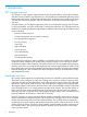
1 Introduction XP7 Storage overview XP7 Storage is a high capacity, high performance disk array that offers a wide range of storage and data services, software, logical partitioning, and simplified and unified data replication across heterogeneous disk arrays. Its large scale, enterprise class virtualization layer combined with Smart Tiers and Thin Provisioning software, delivers virtualization of internal and external storage into one pool.
The following sections provide descriptions and illustrations of XP7 Storage and its components.
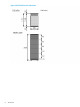
Figure 3 XP7 disk drive rack dimensions 8 Introduction
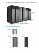
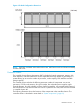
Figure 4 Six Rack Configuration dimensions NOTE: Each Rack is 600mm wide without side covers. Add 5mm to each end of entire assembly for each side cover. Controller chassis The controller chassis (factory designation DKC) includes the logical components, memory, disk drive interfaces, and host interfaces. It can be expanded with a high degree of granularity to a system offering up to twice the number of processors, cache capacity, host interfaces and disk storage capacity.
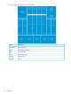
Figure 5 Controller chassis front view (DKC) 10 Item Description DKCPANEL Disk control panel BKM Cache Backup Module Kit MPB Processor Blade MFC Module Fibre Cable CACHE Cache module DKCFAN Fan unit Introduction
Figure 6 Controller chassis rear view (DKC0) Hardware overview 11
Figure 7 Controller chassis rear view (DKC1) Item Description DKCPS Power supply unit MODCON Module connector unit SSVPMN Sub Service Processor and DKC monitor DKCFAN Fan unit DKC Disk controller CHA Channel adapter MPB Multi-processor board Drive chassis The drive chassis (factory designation DKU) consists of SAS switches, slots for 2 1/2 inch, 3 1/2 inch HDD or SSD drives, and four 4 fan door assemblies that can be easily opened to allow access to the drives.
Figure 8 2.
Figure 9 3.5 inch drive chassis Figure 10 Flash module drive chassis Features This section describes the main features of XP7 Storage.
Scalability XP7 Storage is highly scalable and can be configured in several ways as needed to meet customer requirements: • The minimum configuration is a single rack containing one controller chassis and two drive chassis. • One to three racks containing one controller chassis and up to eight drive chassis. A drive chassis can contain up to 192 2 1/2 disk drives, 96 3 1/2 disk drives, or 192 SSDs. Drives can be intermixed. See Table 2 (page 19) for details.
In addition to the number of disk drives, the system can be configured with disk drives of different capacities and speeds, varying numbers of CHAs and DKAs, and varying cache capacities, as follows: 16 • Two to six CHAs (each is a pair of boards). This provides a total of 12 when all of the CHA slots are used and there are no DKAs installed, as in a diskless system. The maximum total number of CHAs and DKAs is 12. • Two to four DKAs (each is a pair of boards).
• Hard Disk drive capacities of 300 GB, 600 GB, 900 GB , 1.2 TB, and 4 TB. • Solid State Disk Drive capacities of 400 GB, 800 GB. • Channel ports: 80 for one module, 176 for two modules. High performance The XP7 includes several new features that improve the performance over previous models. These include: • 8 GBps only Fibre Channel for CHAs without the limitation of microprocessors on each board. • SSD flash drives with ultra high speed response.
Non disruptive service and upgrades XP7 Storage is designed so that service and upgrades can be performed without interrupting normal operations. These features include: • Main components can be “hot swapped” — added, removed, and replaced without any disruption — while the disk array is in operation. The front and rear fan assemblies can be moved out of the way to enable access to disk drives and other components, but not both at the same time.
Table 1 XP7 specifications (continued) Item Internal Path Size Single Module RAID6 6D+2P Architecture Hierarchical Star Net Maximum Bandwidth Cache Path = 128 GB/s Dual Module Control Path = 64 GB/s Back-end Path SAS 6G 32 (2WL*6) 64 (2WL*32) Number of ports per installation unit FC 2/4/8G 80 /16,8 160/16,8 Device I/F Controller chassis SAS/Dual Port drive chassis Interface Data transfer rate Max. 6 GBps Maximum number 256 (2.
Table 2 Drive specifications (continued) Drive Type Size Drive Capacity Speed (RPM) HDD, 3 1/2 inch 96 1152 2304 2 2562 SSD (Flash) 1 128 128 Notes. 1. SSD drives can be mounted all in one drive chassis or spread out among all of the chassis in the storage system. 2. Recommended maximum number. The drives must be added four at a time to create RAID groups, unless they are spare drives.
Table 5 Provisioning features and functions for Open systems (continued) Feature Description Thin Provisioning The Thin Provisioning feature virtualizes some or all of the system's physical storage. This simplifies administration and addition of storage, eliminates application service interruptions, and reduces costs.
Table 8 Security features and functions (continued) Feature Description tenant environments. It also provides enhanced data security for the AES-XTS mode of operations. External Authentication and Authorization Storage management users of XP7 systems can be authenticated and authorized for storage management operations using existing customer infrastructure such as Microsoft Active Directory, LDAP, and RADIUS based systems.
2 Functional and operational characteristics System architecture overview This section briefly describes the architecture of XP7 Storage. Hardware architecture The basic system architecture is shown in the following diagram. Figure 12 XP7 architecture overview The system consists of two main hardware assemblies: • A controller chassis that contains the logic and processing components • A drive chassis that contains the disk drives or solid state drives.
Array groups and RAID levels The array group (also called parity group) is the basic unit of storage capacity for XP7 Storage. Each array group is attached to both boards of a DKA pair over 2 SAS paths, which enables all data drives in the array group to be accessed simultaneously by a DKA pair. Each controller rack has two drive chassis (factory designation DKU), and each drive chassis can have up to 128 physical data drives. The XP7 supports the following RAID levels: RAID1, RAID5, RAID6.
configured as either 3390-x or OPEN-x logical devices. All LDEVs in the array group must be the same format (3390-x or OPEN-x). For open systems, each LDEV is mapped to a SCSI address, so that it has a TID and logical unit number (LUN). Figure 14 Sample RAID5 3D + 1P layout (data plus parity stripe) RAID6. A RAID6 array group consists of eight data drives (6D+2P). The data is written across the eight drives in a stripe that has six data chunks and two parity chunks.
Figure 15 LDEV striping across 2 RAID5 (7D+1P) array groups Figure 16 LDEV striping across 4 RAID5 (7D+1P) array groups All data drives and device emulation types are supported for LDEV striping. LDEV striping can be used in combination with all XP7 data management functions. CU Images, LVIs, and Logical Units This section provides information about control unit images, logical volume images, and logical units.
The mainframe data management features of the XP7 may have restrictions on CU image compatibility. For further information on CU image support, see the Mainframe Host Attachment and Operations Guide, or contact HP. Logical Volume images The XP7 supports the following mainframe LVI types: • 3390-3, -3R, -9, L, and -M. The 3390-3 and 3390-3R LVIs cannot be intermixed in the same disk array. • 3380-3, -F, -K.
Mainframe operating system support XP7 Storage supports most major IBM Mainframe operating systems and Open System operating systems, such as Microsoft Windows, Oracle Solaris, IBM AIX, Linux, HP-UX, and VMware. For more complete information on the supported operating systems, go to: http://www.hp.com Mainframe configuration After XP7 Storage has been installed, users can configure the disk array for mainframe operations.
Table 11 System option modes Mode Category Description Default MCU/RCU 20 Public R-VOL read only function. OFF MCU Regarding the correction copy or the drive copy, in case ECCs/LRC PINs are set on the track of copy source HDD, mode 22 can be used to interrupt the copy processing (default) or to create ECCs/LRC PINs on the track of copy target HDD to continue the processing.
Table 11 System option modes (continued) Mode Category Description Default MCU/RCU • Pair status: Duplex/Pending • A pair whose RCU# is identical to the RCU for which the Freeze command is specified. 64 (cont) Continuous Access Notes: . Synchronous Z 1. When all the following conditions are met, set Mode 64=ON. 2. When all the following conditions are met, set Mode 64=ON.
Table 11 System option modes (continued) Mode Category Description Default MCU/RCU 1. If you select an incorrect port while the mode is set to ON, and if ESTPATH is executed when no logic path exists, the port is switched to RCP.. 2. Set this mode to OFF before using TPC-R (IBM software for disaster recovery).
Table 11 System option modes (continued) Mode Category Description Default MCU/RCU OFF - OFF MCU/RCU OFF MCU/RCU OFF MCU Notes: 1. For more details about mode 269, see worksheet "Mode269 detail for RAID700". 2. Mode 269 is effective only when using the SVP to format the CVS. 278 Open Tru64 (Host Mode 07) and OpenVMS (Host Mode 05) Caution: Host offline: Required 292 HRC Issuing OLS when Switching Port In case the mainframe host (FICON) is connected with the CNT-made FC switch (FC9000 etc.
Table 11 System option modes (continued) Mode Category Description Default 448 Continuous Access Mode 448 = ON: (Enabled) OFF Journal If the SVP detects a blocked path, the SVP assumes that an error Continuous Access occurred, and then immediately splits (suspends) the mirror. Journal Z Mode 448 = OFF: (Disabled) MCU/RCU If the SVP detects a blocked path and the path does not recover within the specified period of time, the SVP assumes that an error occurred, and then splits (suspends) the mirror.
Table 11 System option modes (continued) Mode Category Description Default MCU/RCU 457 External Storage 1. High Speed LDEV Format for External Volumes OFF MCU/RCU Mode 457 = ON: The high speed LDEV format for external volumes is available by setting system option mode 457 to ON. When System Option Mode 457 is ON, when selecting the external volume group and performing the LDEV format, any Write processing on the external logical units will be skipped.
Table 11 System option modes (continued) Mode Category Description Default Snapshot, Auto LUN, External Storage Business Copy, Business Copy Z, Compatible FlashCopy, Snapshot, Auto LUN, External Storage MCU/RCU Mode 467 = ON: Copy overload prevention. Copy processing stops when the percentage of “dirty” data reaches 60% or higher. When the percentage falls below 60%, copy processing restarts. Mode 467 = OFF: Normal operation.
Table 11 System option modes (continued) Mode Category Description Default MCU/RCU - Initial copy operation is prioritized over update I/O. Therefore, the processing speed of the update I/O slows down by about 15?s per command. 3. If this mode is set to ON, the processing speed of update I/O slows down by about 15?s per command, version downgrade is disabled, and Take Over is not available. 4. If the mode is not set to ON for both or either sides, the behavior is as follows.
Table 11 System option modes (continued) Mode Category Description Default MCU/RCU Note: 1. Make sure to apply mode 491 when the performance of Business Copy/ Business Copy Z/ ShadowImage FCv1 is considered to be important. 2. Make sure not to apply the mode when the host I/O performance is considered to be important. 3. The mode will be noneffective if 3 or more pairs of DKAs are not mounted. 4. Make sure to set mode 467 to OFF when using mode 491, since the performance may not improve. 5.
Table 11 System option modes (continued) Mode Category Description Default MCU/RCU OFF MCU/RCU Prevents an error code from being set in the 8 - 11th bytes in the OFF standard 16-byte sense byte. MCU/RCU Manager or Storage Navigator may show earlier time than the time showed when the pair was in the Duplex state. 531 Open and Mainframe When PIN data is generated, the SIM currently stored in SVP is reported to the host.
Table 11 System option modes (continued) Mode Category Description Default MCU/RCU Notes: 1. When DKC emulation type is 2105/2107, this mode is applied in the case where pair creation in Cnt Ac-S Z – BC Z cascading configuration in the ICKDSF environment fails with the following message output. Message: ICK30111I DEVICE SPECIFIED IS THE SECONDARY OF A DUPLEX OR PPRC PAIR 2. The CASCADE option can be specified in the TSO environment also. 3.
Table 11 System option modes (continued) Mode Category Description Default MCU/RCU Mode 676 = OFF (default): An audit log is not stored onto the system disk. This mode is also enabled/disabled by enabling/disabling Audit Log Buffer on the [Audit Log Setting...] window, which can be opened by selecting [Settings] -> [Security] -> [Audit Log Setting...] on Storage Navigator. Notes: 1. 1. This option is applied to the sites where the level of importance of an audit log is high. 2.
Table 11 System option modes (continued) Mode Category Description Default MCU/RCU OFF . Issues the Read command at the logical unit discovery operation OFF using Ext Stor. . Read JNL or JNL Restore is not prevented when the Write Pending rate on RCU exceeds 60% (the same as before). Notes: 1. This mode can be set online. 2. This mode should be set per customer’s requests. 3.
Table 11 System option modes (continued) Mode Category Description Default MCU/RCU b. An external volume to which Nondisruptive Migration (NDM) attribute is set exists. 704 Open and Mainframe To reduce the chance of MIH, this option can reduce the priority OFF of BC, VM, CoW Snapshot, Flash Copy or Resync copy internal IO requests so that host IO has a higher priority. This mode creates new work queues where these jobs can be assigned with a lower priority. .
Table 11 System option modes (continued) Mode Category Description Default MCU/RCU OFF . OFF . When Not Ready is returned, the external path is blocked and the path status can be automatically recovered (Not Ready blockade). Note that the two behaviors, automatic recovery and block, may be repeated. For version 60-05-06-00/00 and later, when the status of a device is Not Ready blockade, Device Health Check is executed after 30 seconds.
Table 11 System option modes (continued) Mode Category Description Default MCU/RCU page allocation is not provided at a time when the HDP pool is full. (Not to set in the case of Read request.) Mode 729 = OFF (default): Not to set the Protect attribute for the target DP-VOL using Data Ret, when any write operation is requested to the area where the page allocation is not provided at a time when HDP pool is full. Notes: 1. This SOM is applied when: - The threshold of pool is high (e.g.
Table 11 System option modes (continued) Mode Category Description Default MCU/RCU 1. This option is turned ON to prevent the write I/O operation from being unavailable due to pool full. 2. If the exceeding pool threshold SIM occurs frequently, other SIMs may not be reported. 3. Though turning on this option can increase the warning effect, if measures such as adding a pool fail to be done in time so that the pool becomes full, MODE 729 can be used to prevent file systems from being destroyed. 4.
Table 11 System option modes (continued) Mode Category Description Default MCU/RCU per hour. If SSB=AD02 occurs and a path is blocked, perform Check Paths on this path again. 4. If Check Paths is performed while Business Copy Z pair and Compatible FlashCopy Mirror pair are defined in the specified volume, the Check Paths operation is rejected with a message “605 2518”.
Table 11 System option modes (continued) Mode Category Description Default MCU/RCU The data is settled to RCU according to the time stamp that RCU has received. Notes: 1. This mode is applied under the following conditions. (1)Continuous Access Journal Z. (2) EXCTG configuration. (3) Flush suspension with an EXCTG specified is executed. (4) BCM is installed on the host where the time stamping function is available.
Table 11 System option modes (continued) Mode Category Description Default MCU/RCU OFF MCU/RCU Mode 776 = OFF (default): When the status of P-VOL changes to Suspend during a TC/TCA S-VOL pair suspend or deletion operation from BCM, the F/M=FB message is output to the host. Notes: 1. Set this mode to ON in the environment where TC/TCA for z/OS is used from BCM and the MCU host does not need the F/M=FB message output during an S-VOL pair suspend or deletion operation from BCM. 2.
Table 11 System option modes (continued) Mode Category Description Default MCU/RCU 4. To apply the mode to TC Sync for z/OS, MCU and RCU must be RAID600 or RAID700 and micro-program must be the support version on both sides. 5. If a failure occurs on the switched path between DKCs, Mainframe host MIH or Open server time-out may occur. (Continued below) 784 2 of 2 Continuous Access Notes: (continued) OFF Synchronous 6.
Table 11 System option modes (continued) Mode Category Description Default MCU/RCU OFF - 1. 1. This mode is applied when • - a file system using THP pool VOLs is used. • - Data Retention Utility is installed. 2. 2. Because the DRU attribute is set to Protect for the V-VOL, a read I/O is also disabled. 3. 3. If Data Retention Utility is not installed, the expected effect cannot be achieved. 4. 4.
Table 11 System option modes (continued) Mode Category Description Default MCU/RCU OFF .. LDEV format of the DP-VOL is performed with page reclamation. Mode 867 = OFF (default):LDEV format of the HDP-VOL is performed with 0 data writing. Notes: 1. 1. This mode is applied at recovery after a pool failure. 2. 2. Do not change the setting of the mode during DP-VOL format. 3. 3.
Table 11 System option modes (continued) Mode Category Description Default MCU/RCU OFF .. By the combination of SOM 897 and 898 setting, the expansion OFF width of Tier Range upper I/O value (IOPH) can be changed as follows. .. Notes: 1. To apply the mode, set the RMF version of mainframe to be connected to 1.12 or higher. 2. If the OS does not use a supported version, the transfer speed cannot be displayed correctly.
Table 11 System option modes (continued) Mode Category Description Default MCU/RCU OFF .. OFF .. addition, the settings of SOM 897 and 898 are effective for Tire2 and Tier3. Please also see spreadsheet "SOM 897_898_901" for more details about the relations between SOM 897, 898 and 901. 898 Smart Tiers, Smart Tiers Z I/O value (IOPH) can be changed as follows.
Table 11 System option modes (continued) Mode Category Description Default MCU/RCU SOM899 is OFF: I/O synchronous copy starts when the number of retries reaches half of the threshold of Auto LUN retry. Mode 900 = OFF (default): SOM899 is ON: I/O synchronous copy starts when the threshold of Volume Migration retry is exceeded. (Recommended) SOM899 is OFF: Volume Migration is retired and I/O synchronous copy is not executed. Note: 1.
Table 11 System option modes (continued) Mode Category Description Default MCU/RCU Continuous Access The difference in CM allocation capacity among MPBs with Journal Z different workload is large. Mode 908 = OFF (default): The difference in CM allocation capacity among MPBs with different workload is small (existing operation) Notes: 1. 1. The mode is applied to a CLPR only used for UR JNLGs. 2. 2.
Table 11 System option modes (continued) Mode Category Description high because the migration source and target are in the same parity group or external volume group. 4. When pool shrink is performed per pool VOL from a parity group with multiple pool VOLs defined (or from an external volume group) while the mode is set to ON, the pool shrink takes longer time compared to when the mode is set to OFF.
Table 11 System option modes (continued) Mode Category Description Default MCU/RCU 6. Tier relocation with monitoring data collected when the mode is set to ON is disabled. 7. When THP is converted into Smart (after purchase of PP license), the collected monitoring data is discarded.
• Command tag queuing • Industry-standard failover and logical volume management software • SNMP remote disk array management The XP7’s global cache enables any fibre-channel port to have access to any logical unit in the disk array. In the XP7, each logical unit can be assigned to multiple fibre-channel ports to provide I/O path failover and/or load balancing (with the appropriate middleware support) without sacrificing cache coherency.
Remote Web Console Remote Web Console is installed on a PC, laptop, or workstation. It communicates via a LAN to the SVP in XP7 Storage. The SVP obtains disk array configuration and status information and sends user initiated commands to the disk array. The Remote Web Console GUI displays detailed disk array information and allows users to configure and perform storage operations on the system.
3 System components Controller chassis The controller chassis provides system logic, control, memory, and monitoring, as well as the interfaces and connections to the disk drives and the host servers. The controller chassis consists of the following components: Table 14 Controller chassis Item Description Name Min Max CHA 2 8 if 4 DKAs installed. A CHA is an interface board that provides connection to 12 if no DKAs the host servers. It provides the channel interface control installed.
Table 14 Controller chassis (continued) Item Description Name Min Max . power supplies can be used as needed to provide power to additional components. Cooling fan 10 10 Each fan unit contains two fans to ensure adequate cooling in case one of the fans fails. The following illustrations show the front and rear views of a controller chassis that is configured with the minimum number of components. The system control panel (#1 in the front view) is described in the next section.
Figure 19 Controller chassis rear view Item Description Item Description 1 Power Supply 2 Sub Service Processor (SSVP) and monitor (DKCMN). 3 Module connector (MODCON) 4 Rear (Fans) 5 Channel adapters, switch adapters, expansion slots 6 Service processor and hub System control panel The following illustration shows the XP7 system control panel. The table following the illustration explains the purpose of each of the controls and LEDs on the panel.
Figure 20 XP7 system control panel Item Description Item Description 1 MESSAGE - Amber LED 2 ALARM - Red LED ON: indicates that a SIM (Message) was generated from either of the clusters. Applied to both storage clusters. Indicates DC under voltage of any DKC part, DC over current, abnormally high temperature, or that an unrecoverable failure occurred. Blinking: Indicates that a SVP failure has occurred.
Figure 21 DKC Panel Jumpers Jumper Use JP1 Used for the following actions (mainframe only): • Unfence a fenced path • Release Write Inhibit JP2 Used to Reset PS ALARM and TH ALARM conditions JP3 When this jumper is set, the SSVP detection alarm is reset. An IMPL of the SSVP is executed. NOTE: When the SVP High Availability Kit is installed, and an SVP failover (SIM RC-7FF3xx) has occurred, first take action to resolve the SVP issue before performing an SSVP reset.
Mainframe hosts can specify special attributes (for example, cache fast write command) to write data (typically sort work data) without write duplexing. This data is not duplexed and is usually given a discard command at the end of the sort, so that the data will not be destaged to the drives. Data protection The XP7 is designed so that it cannot lose data or configuration information from the cache if the power fails.
Figure 22 Flash Module Drive Flash module unit The flash module box (FMU) is a 2U high chassis that contains up to 12 FMDs, plus two redundant power supplies and two redundant SSW adapters.
Table 15 Flash Module Unit Item Description Item 1 FMD Active LED - lights when FMD is activated. 8 Blinks at drive access. SAS / SSW standard OUT connector. 2 FMD Alarm LED - lights when FMD has an error 9 and should be replaced. SAS / SSW high performance OUT connector. 3 SAS / SSW Module Power LED. Power cord receptacle. 4 SAS / SSW Module Alarm LED - indicates fatal 11 error condition. 10 Description Power Supply - 220 VAC input, draws approximately 265 watts.
Cache memory Your XP7 can be configured with up to 512 GB of cache memory per controller chassis (1 TB for a two-module system). Each controller chassis can contain from two to eight cache memory adapter boards. Each board contains from 8 GB to 64 GB. Cache memory adaptor boards are installed in pairs and work together to provide cache and shared memory for the system. Each pair is called a cluster. From one to four cache clusters can be installed in a controller.
Table 18 System capacities with smart flash modules Considering hot sparing requirements R1 2D+2P R5 4D+4P R6 3D+1P 7D+1P 6D+2P 14+2P Single flash chassis, max. capacity 1.6 GB 3.2 GB Raw 70.4 64.0 70.4 64.0 64.0 51.2 Usable 35.2 32.0 52.8 56.0 48.0 44.8 Raw 140.8 128.0 140.8 128.0 128.0 102.4 Usable 70.4 64.0 105.6 112.0 96.0 89.6 Flash chassis pair max. capacity 1.6 GB 3.2 GB Raw 147.2 140.8 147.2 140.8 140.8 128.0 Usable 73.6 70.4 110.4 123.2 105.6 112.
4 Power On/Off procedures Safety and environmental information CAUTION: Before operating or working on XP7 Storage, read the safety section in the HP XP7 Site Preparation Guide and the environmental information in “Regulatory compliance notices” (page 91). Standby mode When the disk array power cables are plugged into the PDUs and the PDU breakers are ON, the disk array is in standby mode. When the disk array is in standby mode: • The Basic Supply (BS) LED on the control panel is ON.
Follow this procedure exactly when powering the disk array on. Refer to the illustration of the control panel as needed. 1. On the control panel, check the amber BS LED and make sure it is lit. It indicates that the disk array is in standby mode. 2. In the PS area on the control panel, move the Enable switch to the ENABLED position. Hold the switch in the Enabled position and move the PS ON switch to the ON position. Then release the ENABLE switch. 3.
Battery backup operations The XP7 is designed so that it cannot lose data or configuration information if the power fails. The battery system is designed to provide enough power to completely destage all data in the cache if two consecutive power failures occur and the batteries are fully charged. If the batteries do not contain enough charge to provide sufficient time to destage the cache when a power failure occurs, the cache operates in write through mode.
When the batteries are connected and the power is off, the batteries slowly discharge. They will have a charge of less than 50% after two weeks without power. When fully discharged, the batteries must be connected to power for three hours to fully recharge. NOTE: The disk array generates a SIM when the cache destage batteries are not charged to at least 50%. The LEDs on the front panel of the cache boards also show the status of the batteries.
5 Troubleshooting Solving problems XP7 Storage is highly reliable and is not expected to fail in any way that would prevent access to user data. The READY LED on the control panel must be ON when the disk array is operating online. The following table lists possible error conditions and provides recommended actions for resolving each condition. If you are unable to resolve an error condition, contact your HP representative, or call the support center for assistance.
Figure 26 Service Information Message C-Track The C-Track remote support solution detects and reports events to the HP Support Service. C-Track transmits heartbeats, SIMs, and configuration information for remote data collection and monitoring purposes. C-Track also enables the HP Support Service to remotely diagnose issues and perform maintenance (if the customer allows the remote maintenance). The C-Track solution offers Internet connectivity only.
Table 20 XP7 Storage remote support products (continued) HP Product Description Application Access, Critical Support contract prerequisites cannot be met.
Figure 27 Failure reporting process Failure detection and reporting process 77
6 System specifications and requirements This section describes the physical characteristics of XP7 Storage, including • “Mechanical specifications” (page 78) • “Electrical specifications” (page 78) • “Environmental specifications” (page 82) Mechanical specifications The following table lists the mechanical specifications of XP7 Storage. Table 21 XP7 mechanical specifications Dimension One Rack Two Racks Three Racks Four Racks Five Racks Six Racks Width 24.0 inches 47.6 inches 71.
Table 23 System components heat and power specifications Component Product Number HP XP7 Storage Component Power Consumption Heat Output (kW)1 (kVA)1 H6F62A Flash Module Chassis 0.6004 0.6404 H6G70A, H6G71A Flash Module 0.0173 0.0183 H6F56A Disk Array DKC Module-0 Rack 1.88 1.97 H6F57A DKC Module-1 Rack 1.83 1.93 H6F62A Flash Module Chassis 0.6004 0.6404 H6G70A 1.6TB Flash Module 0.0173 0.0183 H6G71A 3.2TB Flash Module 0.0183 0.0193 H6F56A Disk Array DKC Module-0 Rack 1.
Table 23 System components heat and power specifications (continued) Power Consumption Heat Output (kW)1 (kVA)1 Component Product Number HP XP7 Storage Component 2 Power is consumed during the battery back-up time only. 3 Actual values at a typical I/O condition. (Random Read and Write, 50 IOPSs for HDD, 2500 IOPSs for SSD, Data Length: 8 KB). These values may increase for future compatible drives. 4 Maximum values with all fans rotate at maximum.
Table 24 XP7 AC PDU Options (continued) Product Number Local Power Branch circuit Number of requirements PDU per Rack1 per PDU Plug Type Facility receptacle needed Notes Distribution System H6F73A 3 phase (5 wire) 2 380-415V, 3Ø, 5-wire, 16A IEC60309 4 pole, 5-wire 380-415VAC, 16A IEC60309 4 pole, 5-wire, 380-415 VAC, 16A For customers with 380 - 415 VAC, Three-Phase, 5-Wire Wye Power Distribution System H6F70A single phase NEMA 4 200-240V, 1Ø, NEMA L6-30P NEMA L6-30R For customers 3-wire, 3
Figure 28 Direct Power Connection Figure 29 Power Connection via UPS Environmental specifications Table 26 (page 83)provides the environmental specifications and requirements for XP7 Storage.
Table 26 XP7 Environmental specifications Item Temperature ºC Operating Not Operating In Storage -25 to 60 60.8 - 80.9 / -10 to 43 16 to 32 -10 to 358 Relative Humidity (%)2 20 to 80 8 to 90 5 to 95 Max. Wet Bulb ºC 26 27 29 Temperature Deviation ºC 10 per hour) 10 20 Vibration to 10Hz: 0.25 mm 5 to 10Hz: 0.25 mm 5 to 10 Hz: 2.5 mm 10 to 300Hz: 10 to 70 Hz: 4.9 m/s1 0.49m/s2 70 to 99 Hz: 0.05 mm 99 to 300 Hz: 9.8 m/s1 Sine Vibration: 4.9 m/s1, 5 min.
Table 27 Heat, power, and airflow Model Number Heat Output (kW) Power Consumption (kVA) Air Flow (M3/min) H6F62A HP XP7 Flash Module Chassis 0.6006 0.6406 - H6G70A HP XP7 1.6TB Flash 0.0173 Module 0.0183 - H6G71A HP XP7 3.2TB Flash 0.0183 Module 0.0193 - H6F56A - HP XP7 Storage DKC Module-0 Rack 1.881 1.971 25 H6F57A - HP XP7 DKC Module-1 Rack 1.831 1.931 25 H6F60A HP XP7 Base 2.5in Drive Chassis see note 5 see note 5 - 0.57 0.600 - H6F60A Complete 2.
Table 27 Heat, power, and airflow (continued) Model Number Heat Output (kW) 3 H6G43A - HP XP7 1.2TB SAS 0.0082 7.2K 2.5in DP HDD 3 H6G40A - HP XP7 300GB SAS 10K 2.5in DP HDD 0.0063 H6G41A - HP XP7 600GB SAS 10K 2.5in DP HDD 0.0080 3 3 H6G43A - HP XP7 1.2TB 6G 0.0083 SAS 10K 2.5in DP HDD 3 Power Consumption (kVA) 3 0.0087 3 0.0067 3 0.0085 3 0.0087 3 H6G40A - HP XP7 300GB SAS 15K 2.5in DP HDD 0.0086 0.0090 H6G42A - HP XP7 900GB SAS 15K 2.5in DP HDD 0.00902 0.
7 Support and other resources Contacting HP For worldwide technical support information, see the HP support website: http://www.hp.
• 1 GB (gigabyte) = 1,0003 bytes • 1 TB (terabyte) = 1,0004 bytes • 1 PB (petabyte) = 1,0005 bytes • 1 EB (exabyte) = 10006 bytes HP XPXP7 storage systems use the following values to calculate logical storage capacity values (logical devices): • 1 block = 512 bytes • 1 KB (kilobyte) = 1,024 (210) bytes • 1 MB (megabyte) = 1,0242 bytes • 1 GB (gigabyte) = 1,0243 bytes • 1 TB (terabyte) = 1,0244 bytes • 1 PB (petabyte) = 1,0245 bytes • 1 EB (exabyte) = 10246 bytes Conventions for storage
A Comparing the XP24000/XP20000 Disk Array and XP7 Comparison of the XP24000/XP20000 Disk Array and XP7 The XP7 includes several upgrades from the XP24000/XP20000 Disk Array as well as a number of new features. These include: • High scalability. The system supports configurations of 2 1/2 disk drives in either a single or dual DKC configuration • Shared processors. In the XP7, the processor and interface cards are separate.
Table 29 Basic Mainframe functional differences (continued) Feature Operation Interface XP7 XP24000/XP20000 Disk Array /OS V1R0 or higher z/OS V1R0 or higher z/VM V5R3 or higher z/VM V5R3 or higher z/VSE V4R1 or higher z/VSE V4R1 or higher TSO TSO ICKDSF ICKDSF DFSMSdss DFSMSdss ANTRQS ANTRQS Table 30 Functional differences - Business Copy Z .
Table 31 Functional differences - Business Copy for Open Systems (continued) .
B Regulatory compliance notices This section contains regulatory notices for XP7 Storage. Regulatory compliance identification numbers For the purpose of regulatory compliance certifications and identification, this product has been assigned a unique regulatory model number. The regulatory model number can be found on the product nameplate label, along with all required approval markings and information. When requesting compliance information for this product, always refer to this regulatory model number.
off and on, the user is encouraged to try to correct the interference by one or more of the following measures: • Reorient or relocate the receiving antenna. • Increase the separation between the equipment and receiver. • Connect the equipment into an outlet on a circuit that is different from that to which the receiver is connected. • Consult the dealer or an experienced radio or television technician for help.
This compliance is indicated by the following conformity marking placed on the product: This marking is valid for non-Telecom products and EU harmonized Telecom products (e.g., Bluetooth). Certificates can be obtained from http://www.hp.com/go/certificates.
Class B equipment Taiwanese notices BSMI Class A notice Taiwan battery recycle statement Turkish recycling notice Türkiye Cumhuriyeti: EEE Yönetmeliğine Uygundur 94 Regulatory compliance notices
Laser compliance notices English laser notice This device may contain a laser that is classified as a Class 1 Laser Product in accordance with U.S. FDA regulations and the IEC 60825-1. The product does not emit hazardous laser radiation. WARNING! Use of controls or adjustments or performance of procedures other than those specified herein or in the laser product's installation guide may result in hazardous radiation exposure.
German laser notice Italian laser notice Japanese laser notice 96 Regulatory compliance notices
Spanish laser notice Recycling notices English recycling notice Disposal of waste equipment by users in private household in the European Union This symbol means do not dispose of your product with your other household waste. Instead, you should protect human health and the environment by handing over your waste equipment to a designated collection point for the recycling of waste electrical and electronic equipment.
Bulgarian recycling notice Изхвърляне на отпадъчно оборудване от потребители в частни домакинства в Европейския съюз Този символ върху продукта или опаковката му показва, че продуктът не трябва да се изхвърля заедно с другите битови отпадъци. Вместо това, трябва да предпазите човешкото здраве и околната среда, като предадете отпадъчното оборудване в предназначен за събирането му пункт за рециклиране на неизползваемо електрическо и електронно борудване.
Estonian recycling notice Äravisatavate seadmete likvideerimine Euroopa Liidu eramajapidamistes See märk näitab, et seadet ei tohi visata olmeprügi hulka. Inimeste tervise ja keskkonna säästmise nimel tuleb äravisatav toode tuua elektriliste ja elektrooniliste seadmete käitlemisega egelevasse kogumispunkti. Küsimuste korral pöörduge kohaliku prügikäitlusettevõtte poole.
Greek recycling notice Απόρριψη άχρηοτου εξοπλισμού από ιδιώτες χρήστες στην Ευρωπαϊκή Ένωση Αυτό το σύμβολο σημαίνει ότι δεν πρέπει να απορρίψετε το προϊόν με τα λοιπά οικιακά απορρίμματα. Αντίθετα, πρέπει να προστατέψετε την ανθρώπινη υγεία και το περιβάλλον παραδίδοντας τον άχρηστο εξοπλισμό σας σε εξουσιοδοτημένο σημείο συλλογής για την ανακύκλωση άχρηστου ηλεκτρικού και ηλεκτρονικού εξοπλισμού. Για περισσότερες πληροφορίες, επικοινωνήστε με την υπηρεσία απόρριψης απορριμμάτων της περιοχής σας.
Lithuanian recycling notice Nolietotu iekārtu iznīcināšanas noteikumi lietotājiem Eiropas Savienības privātajās mājsaimniecībās Šis simbols norāda, ka ierīci nedrīkst utilizēt kopā ar citiem mājsaimniecības atkritumiem. Jums jārūpējas par cilvēku veselības un vides aizsardzību, nododot lietoto aprīkojumu otrreizējai pārstrādei īpašā lietotu elektrisko un elektronisko ierīču savākšanas punktā. Lai iegūtu plašāku informāciju, lūdzu, sazinieties ar savu mājsaimniecības atkritumu likvidēšanas dienestu.
Slovak recycling notice Likvidácia vyradených zariadení používateľmi v domácnostiach v Európskej únii Tento symbol znamená, že tento produkt sa nemá likvidovať s ostatným domovým odpadom. Namiesto toho by ste mali chrániť ľudské zdravie a životné prostredie odovzdaním odpadového zariadenia na zbernom mieste, ktoré je určené na recykláciu odpadových elektrických a elektronických zariadení. Ďalšie informácie získate od spoločnosti zaoberajúcej sa likvidáciou domového odpadu.
French battery notice German battery notice Battery replacement notices 103
Italian battery notice Japanese battery notice 104 Regulatory compliance notices
Spanish battery notice Battery replacement notices 105
Glossary access method An IBM-specific term for software that moves data between main storage and I/O devices to create channel programs and manage system buffers. BC An HP application that provides volume-level, point-in-time copies in the disk array. BC Z The version of Business Copy that supports mainframe volumes. CLI Command-line interface. An interface comprised of various commands which are used to control operating system responses. CLPR Cache logical partition.
MCU Main control unit. OPEN-x A general term describing any of the supported OPEN emulation modes (for example, OPEN-E). There are two types of OPEN-x devices: legacy OPEN-x devices with a fixed size (such as OPEN-3, OPEN-8, OPEN-9, and OPEN-E), and OPEN-V, which has a variable size and is a CVS-based volume. parity group A set of hard disk drives that have the same capacity and that are treated as one group.
Index A architecture system, 23 B obtaining, 86 host modes, 57 HP subscription service, 86 technical support, 86 hub, 60 basic configuration;configuration basic, 6 battery replacement notices, 102 J C K cache, 60 Canadian notice, 92 capacity cache, 16 disk drive, 17 chassis controller, 60 controller, components, 60 components controller chassis, 60 configuration maximum, 15 minimum, 15 contacting HP, 86 controller chassis, 9, 15 controller, components, 9, 60 controls description, 62 system, 62 conven
S safety, 70 service processor, 60 specifications, 78 drive, 16, 19 electrical, 78 environmental, 82 equipment noise, 85 general, 18 heat output, 83 mechanical, 78 storage capacity values conventions, 86 subscription service, HP, 86 SVP, 60 switches control, 62 ESW, 60 power, 71 system reliability, 6 T Taiwanese notices, 94 technical support HP, 86 technological advances, 6 V virtualization, 6 W web sites HP subscription service, 86 websites product manuals, 86 109