
HP XP7 Owner Guide (H6F56-96006)
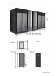
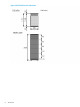
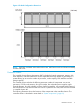
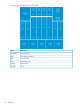

Figure 4 Six Rack Configuration dimensions
NOTE: Each Rack is 600mm wide without side covers. Add 5mm to each end of entire assembly
for each side cover.
Controller chassis
The controller chassis (factory designation DKC) includes the logical components, memory, disk
drive interfaces, and host interfaces. It can be expanded with a high degree of granularity to a
system offering up to twice the number of processors, cache capacity, host interfaces and disk
storage capacity.
The controller chassis includes the following maximum number of components: two service
processors, 512 GB cache memory, four grid switches, four redundant power supplies, eight
channel adapters, four disk adapters, and ten dual fan assemblies. It is mounted at the bottom of
the rack because it is the heavier of the two units. If a system has two SVPs, both SVPs are mounted
in controller chassis #0.
The following illustration shows the locations of the components in the controller chassis. The
controller chassis is described in more detail in “System components” (page 60).
Hardware overview 9