
HP StorageWorks SAN Virtualization Services Platform Data Path Module rail installation instructions (5697-0297, January 2010)

Attach rails to the Data Path Module
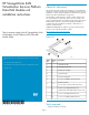
1. Remove the two 4–40 x 0.25 flat head screws from both sides of
the Data Path Module. The screws are located toward the Power
Cooling Module (PCM).
10–32 x 0.38 flat head
screws
3Data Path Module rails1
4–40 x 0.25 flat head
screws
2
2. Position one rail on each side of the Data Path Module. The rail is
correctly positioned when you can reinstall a 4–40 x 0.25 flat head
screw through the tab in the rail.
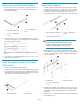
3. Reinstall a 4–40 x 0.25 flat head screw through the tab in each
rail.
4. Secure the rails to the Data Path Module using two 10–32 x 0.38
flat head screws in each rail.
Install the support bracket to the Data
Path Module
1. Remove the existing PCM retaining bracket.
2. Install the support bracket in place of the PCM retaining T-bracket.
It is important that the support bracket be installed while the DPM
is laying fully on a flat surface. There should be no flexing or bowing
of the chassis when the support bracket is secure.
Support bracket2Data Path Module1
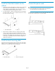
Install rails to cabinet
1. Assemble each inner cabinet mounting rail with an outer cabinet
mounting rail. Use four 6–32 x 0.38 flat head screws in each rail
assembly. In some applications you can use five 6–32 x 0.38 flat
head screws. Insert the screws through the outer rail into the
captured nuts in the inner rail. Do no tighten the screws at this time.
6–32 x 0.38 flat head
screws
3Outer cabinet mounting rail1
Inner cabinet mounting rail2
WARNING!
Heavier products should be placed near the bottom of
a cabinet. A top-heavy cabinet can become unstable,
resulting in equipment damage or personal injury.
2. Extend the cabinet rails to fit the inner dimensions of the cabinet.
The rail flanges on both ends fit inside the cabinet. Be sure that the
inner rail is toward the PCM end of the Data Path Module (which
is the air intake end).
Centering washer3Cabinet rail1
10–32 x 0.38 pan head
screw
2
3. Fasten the rail assemblies to the cabinet. Insert two 10–32 x 0.38
pan head screws through the cabinet and into the upper and lower
captured nuts in each rail flange (eight total screws for both rail
assemblies).
4. Tighten the 6–32 x 0.38 flat head screws in each rail assembly that
were installed in step 1.
Page 2