
Optimizing Serviceguard Failover Time, Version A.11.19 and later, April 2009


2
Introduction
One of the most important measurements for an effective high availability or mission-critical
environment is how much delay the end user notices in the event of a failure. In these environments,
certain things need to take place, such as detecting a failure, finding a way to restart the service,
ensuring data integrity, and restarting applications and making them available to users.
Different business needs require different environments. Environments vary widely in their tolerance
for unplanned downtime, their hardware configuration, specialized software, and system and data
management. These factors require careful consideration when configuring a high-availability
environment. Thorough testing in a production or near-production environment should be done to
make sure that the configured cluster meets the requirements. Testing and fine-tuning can help
optimize failover time and increase application availability to end users.
This paper explains the HP Serviceguard failover process and discusses how you can optimize your
cluster failover time.
This whitepaper is applicable for Serviceguard A.11.19.00 and later. For a whitepapers applicable
to the previous Serviceguard version, see Optimizing failover time in a Serviceguard environment,
available from www.docs.hp.com/hpux/ha.
The HP Serviceguard failover process
What happens when failover is triggered by a node failure
Serviceguard nodes monitor each other to be sure they can all communicate and cooperate. Every
node in a Serviceguard cluster sends heartbeat messages over the network and listens for heartbeat
messages from other nodes. Heartbeat messages are sent at regular intervals of 1 second or ¼ of
MEMBER_TIMEOUT, whichever is shorter.
MEMBER_TIMEOUT is configurable via the cluster configuration file. It specifies the amount of time
Serviceguard will wait before declaring that a node has failed.
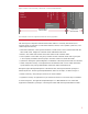
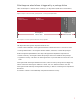
Once Serviceguard declares that a node has failed, it begins the process of re-forming the cluster
without the unreachable node. Figure 1 shows the steps in a failover caused by a failed node.