HP Serviceguard Extended Distance Cluster for Linux A.01.
Legal Notices © Copyright 2006-2008 Hewlett-Packard Development Company, L.P. Publication Date: 2008 Valid license from HP required for possession, use, or copying. Consistent with FAR 12.211 and 12.212, Commercial Computer Software, Computer Software Documentation, and Technical Data for Commercial Items are licensed to the U.S. Government under vendor’s standard commercial license. The information contained herein is subject to change without notice.
Contents 1. Disaster Tolerance and Recovery in a Serviceguard Cluster Evaluating the Need for Disaster Tolerance . . . . . . . . . . . . . . . . . . . . . . . . . . . . . . . . . What is a Disaster Tolerant Architecture? . . . . . . . . . . . . . . . . . . . . . . . . . . . . . . . . . . . Understanding Types of Disaster Tolerant Clusters . . . . . . . . . . . . . . . . . . . . . . . . . . . Extended Distance Clusters. . . . . . . . . . . . . . . . . . . . . . . . . . . . . . . . . . . . . . . . . . . . .
Contents Creating a Multiple Disk Device . . . . . . . . . . . . . . . . . . . . . . . . . . . . . . . . . . . . . . . . . . . 72 To Create and Assemble an MD Device. . . . . . . . . . . . . . . . . . . . . . . . . . . . . . . . . . . . 72 Creating Volume Groups and Configuring VG Exclusive Activation on the MD Mirror . 74 Configuring the Package Control Script and RAID Configuration File . . . . . . . . . . . . 76 Creating and Editing the Package Control Scripts. . . . . . . . . . . . . . . . . . . . . . .
Contents 5
Contents 6
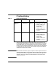
Printing History Table 1 Editions and Releases Printing Date Part Number Edition Operating System Releases (see Note below) November 2006 T2808-90001 Edition 1 • Red Hat 4 U3 or later • Novell SUSE Linux Enterprise Server 9 SP3 or later • Novell SUSE Linux Enterprise Server 10 or later • Red Hat 4 U3 or later • Novell SUSE Linux Enterprise Server 9 SP3 or later • Novell SUSE Linux Enterprise Server 10 or later May 2008 T2808-90006 Edition 2 The printing date and part number indicate t
HP Printing Division: Business Critical Computing Business Unit Hewlett-Packard Co. 19111 Pruneridge Ave.
Preface This guide introduces the concept of Extended Distance Clusters (XDC). It describes how to configure and manage HP Serviceguard Extended Distance Clusters for Linux and the associated Software RAID functionality. In addition, this guide includes information on a variety of Hewlett-Packard (HP) high availability cluster technologies that provide disaster tolerance for your mission-critical applications.
Preface Related Publications The following documents contain additional useful information: • Clusters for High Availability: a Primer of HP Solutions, Second Edition.
Disaster Tolerance and Recovery in a Serviceguard Cluster 1 Disaster Tolerance and Recovery in a Serviceguard Cluster This chapter introduces a variety of Hewlett-Packard high availability cluster technologies that provide disaster tolerance for your mission-critical applications. It is assumed that you are already familiar with Serviceguard high availability concepts and configurations.
Disaster Tolerance and Recovery in a Serviceguard Cluster Evaluating the Need for Disaster Tolerance Evaluating the Need for Disaster Tolerance Disaster tolerance is the ability to restore applications and data within a reasonable period of time after a disaster.
Disaster Tolerance and Recovery in a Serviceguard Cluster Evaluating the Need for Disaster Tolerance line inoperable as well as the computers. In this case disaster recovery would be moot, and local failover is probably the more appropriate level of protection. On the other hand, you may have an order processing center that is prone to floods in the winter. The business loses thousands of dollars a minute while the order processing servers are down.
Disaster Tolerance and Recovery in a Serviceguard Cluster What is a Disaster Tolerant Architecture? What is a Disaster Tolerant Architecture? In a Serviceguard cluster configuration, high availability is achieved by using redundant hardware to eliminate single points of failure. This protects the cluster against hardware faults, such as the node failure in Figure 1-1. Figure 1-1 High Availability Architecture.
Disaster Tolerance and Recovery in a Serviceguard Cluster What is a Disaster Tolerant Architecture? impact. For these types of installations, and many more like them, it is important to guard not only against single points of failure, but against multiple points of failure (MPOF), or against single massive failures that cause many components to fail, such as the failure of a data center, of an entire site, or of a small area.
Disaster Tolerance and Recovery in a Serviceguard Cluster Understanding Types of Disaster Tolerant Clusters Understanding Types of Disaster Tolerant Clusters To protect against multiple points of failure, cluster components must be geographically dispersed: nodes can be put in different rooms, on different floors of a building, or even in separate buildings or separate cities.
Disaster Tolerance and Recovery in a Serviceguard Cluster Understanding Types of Disaster Tolerant Clusters architecture are followed. Extended distance clusters were formerly known as campus clusters, but that term is not always appropriate because the supported distances have increased beyond the typical size of a single corporate campus. The maximum distance between nodes in an extended distance cluster is set by the limits of the data replication technology and networking limits.
Disaster Tolerance and Recovery in a Serviceguard Cluster Understanding Types of Disaster Tolerant Clusters Figure 1-3 Extended Distance Cluster In the above configuration the network and FC links between the data centers are combined and sent over common DWDM links. Two DWDM links provide redundancy. When one of them fails, the other may still be active and may keep the two data centers connected.
Disaster Tolerance and Recovery in a Serviceguard Cluster Understanding Types of Disaster Tolerant Clusters Figure 1-4 Two Data Center Setup Figure 1-4 shows a configuration that is supported with separate network and FC links between the data centers. In this configuration, the FC links and the Ethernet networks are not carried over DWDM links. But each of these links is duplicated between the two data centers, for redundancy.
Disaster Tolerance and Recovery in a Serviceguard Cluster Understanding Types of Disaster Tolerant Clusters Also note that the networking in the configuration shown is the minimum. Added network connections for additional heartbeats are recommended. Benefits of Extended Distance Cluster 22 • This configuration implements a single Serviceguard cluster across two data centers, and uses either Multiple Device (MD) driver for data replication.
Disaster Tolerance and Recovery in a Serviceguard Cluster Understanding Types of Disaster Tolerant Clusters Cluster Extension (CLX) Cluster A Linux CLX cluster is similar to an HP-UX metropolitan cluster and is a cluster that has alternate nodes located in different parts of a city or in nearby cities. Putting nodes further apart increases the likelihood that alternate nodes will be available for failover in the event of a disaster.
Disaster Tolerance and Recovery in a Serviceguard Cluster Understanding Types of Disaster Tolerant Clusters Figure 1-5 shows a CLX for a Linux Serviceguard cluster architecture. Figure 1-5 CLX for Linux Serviceguard Cluster A key difference between extended distance clusters and CLX clusters is the data replication technology used. The extended distance cluster uses Fibre Channel and Linux MD software mirroring for data replication.
Disaster Tolerance and Recovery in a Serviceguard Cluster Understanding Types of Disaster Tolerant Clusters Benefits of CLX • CLX offers a more resilient solution than Extended Distance Cluster, as it provides complete integration between Serviceguard’s application package and the data replication subsystem. The storage subsystem is queried to determine the state of the data on the arrays. CLX knows that application package data is replicated between two data centers.
Disaster Tolerance and Recovery in a Serviceguard Cluster Understanding Types of Disaster Tolerant Clusters • Disk resynchronization is independent of CPU failure (that is, if the hosts at the primary site fail but the disk remains up, the disk knows it does not have to be resynchronized).
Disaster Tolerance and Recovery in a Serviceguard Cluster Understanding Types of Disaster Tolerant Clusters "objective" can be set for the recovery point such that if data is updated for a period less than the objective, automated failover can occur and a package will start. If the time is longer than the objective, then the package will not start. In a Linux environment, this is a user configurable parameter: RPO_TARGET. • Extended Distance Cluster disk reads may outperform CLX in normal operations.
Disaster Tolerance and Recovery in a Serviceguard Cluster Understanding Types of Disaster Tolerant Clusters Figure 1-6 Continental Cluster node 1b node 2b pkg A_R pkg B_R High Availability Network Los Angeles Cluster: Data Center A node 1a node 2a pkg A pkg B New York Cluster: Data Center B WAN Data Replication and/or Mirroring Continentalclusters provides the flexibility to work with any data replication mechanism.
Disaster Tolerance and Recovery in a Serviceguard Cluster Understanding Types of Disaster Tolerant Clusters Benefits of Continentalclusters • You can virtually build data centers anywhere and still have the data centers provide disaster tolerance for each other. Since Continentalclusters uses two clusters, theoretically there is no limit to the distance between the two clusters.
Disaster Tolerance and Recovery in a Serviceguard Cluster Understanding Types of Disaster Tolerant Clusters replicate the data between two data centers. HP provides a supported integration toolkit for Oracle 8i Standby DB in the Enterprise Cluster Management Toolkit (ECMT). • RAC is supported by Continentalclusters by integrating it with SGeRAC. In this configuration, multiple nodes in a single cluster can simultaneously access the database (that is, nodes in one data center can access the database).
Disaster Tolerance and Recovery in a Serviceguard Cluster Understanding Types of Disaster Tolerant Clusters Table 1-1 Attributes Key Benefit Comparison of Disaster Tolerant Cluster Solutions Extended Distance Cluster Excellent in “normal” operations, and partial failure. Since all hosts have access to both disks, in a failure where the node is running and the application is up, but the disk becomes unavailable, no failover occurs. The node will access the remote disk to continue processing.
Disaster Tolerance and Recovery in a Serviceguard Cluster Understanding Types of Disaster Tolerant Clusters Table 1-1 Attributes Key Limitation 32 Comparison of Disaster Tolerant Cluster Solutions (Continued) Extended Distance Cluster No ability to check the state of the data before starting up the application. If the volume group (vg) can be activated, the application will be started.
Disaster Tolerance and Recovery in a Serviceguard Cluster Understanding Types of Disaster Tolerant Clusters Table 1-1 Attributes Maximum Distance Data Replication mechanism Chapter 1 Comparison of Disaster Tolerant Cluster Solutions (Continued) Extended Distance Cluster 100 Kilometers Host-based, through MD. Replication can affect performance (writes are synchronous). Resynchronization can impact performance. (Complete resynchronization is required in many scenarios that have multiple failures.
Disaster Tolerance and Recovery in a Serviceguard Cluster Understanding Types of Disaster Tolerant Clusters Table 1-1 Attributes Comparison of Disaster Tolerant Cluster Solutions (Continued) Extended Distance Cluster CLX Continentalclusters (HP-UX only) Application Failover type Automatic (no manual intervention required). Automatic (no manual intervention required). Semi-automatic (user must “push the button” to initiate recovery).
Disaster Tolerance and Recovery in a Serviceguard Cluster Understanding Types of Disaster Tolerant Clusters Table 1-1 Attributes Data Replication Link Comparison of Disaster Tolerant Cluster Solutions (Continued) Extended Distance Cluster Dark Fiber CLX Continentalclusters (HP-UX only) Dark Fiber WAN Continuous Access over IP LAN Continuous Access over ATM Dark Fiber (pre-integrated solution) Continuous Access over IP (pre-integrated solution) Continuous Access over ATM (pre-integrated solution) C
Disaster Tolerance and Recovery in a Serviceguard Cluster Understanding Types of Disaster Tolerant Clusters Table 1-1 Attributes DTS Software/ Licenses Required Comparison of Disaster Tolerant Cluster Solutions (Continued) Extended Distance Cluster SGLX + XDC CLX Continentalclusters (HP-UX only) SGLX + SG + CLX XP or CLX EVA Continentalclusters + (Metrocluster Continuous Access XP or Metrocluster Continuous Access EVA or Metrocluster EMC SRDF or Enterprise Cluster Master Toolkit) or Customer-selected
Disaster Tolerance and Recovery in a Serviceguard Cluster Disaster Tolerant Architecture Guidelines Disaster Tolerant Architecture Guidelines Disaster tolerant architectures represent a shift away from the massive central data centers and towards more distributed data processing facilities.
Disaster Tolerance and Recovery in a Serviceguard Cluster Disaster Tolerant Architecture Guidelines Protecting Data through Replication The most significant losses during a disaster are the loss of access to data, and the loss of data itself. You protect against this loss through data replication, that is, creating extra copies of the data. Data replication should: • Ensure data consistency by replicating data in a logical order so that it is immediately usable or recoverable.
Disaster Tolerance and Recovery in a Serviceguard Cluster Disaster Tolerant Architecture Guidelines depending on the volume of data. Some applications, depending on the role they play in the business, may need to have a faster recovery time, within hours or even minutes. On-line Data Replication On-line data replication is a method of copying data from one site to another across a link. It is used when very short recovery time, from minutes to hours, is required.
Disaster Tolerance and Recovery in a Serviceguard Cluster Disaster Tolerant Architecture Guidelines Figure 1-7 Physical Data Replication MD Software RAID is an example of physical replication done in the software; a disk I/O is written to each array connected to the node, requiring the node to make multiple disk I/Os.
Disaster Tolerance and Recovery in a Serviceguard Cluster Disaster Tolerant Architecture Guidelines • The logical order of data writes is not always maintained in synchronous replication. When a replication link goes down and transactions continue at the primary site, writes to the primary disk are queued in a bit-map.
Disaster Tolerance and Recovery in a Serviceguard Cluster Disaster Tolerant Architecture Guidelines • Because there are multiple read devices, that is, the node has access to both copies of data, there may be improvements in read performance. • Writes are synchronous unless the link or disk is down. Disadvantages of physical replication in software are: • As with physical replication in the hardware, the logical order of data writes is not maintained.
Disaster Tolerance and Recovery in a Serviceguard Cluster Disaster Tolerant Architecture Guidelines Figure 1-8 Logical Data Replication node 1 node 1a Network Logical Replication in Software. No direct access to both copies of data. Advantages of using logical replication are: • The distance between nodes is limited only by the networking technology. • There is no additional hardware needed to do logical replication, unless you choose to boost CPU power and network bandwidth.
Disaster Tolerance and Recovery in a Serviceguard Cluster Disaster Tolerant Architecture Guidelines • If the primary database fails and is corrupt, which results in the replica taking over, then the process for restoring the primary database so that it can be used as the replica is complex. This often involves recreating the database and doing a database dump from the replica. • Applications often have to be modified to work in an environment that uses a logical replication database.
Disaster Tolerance and Recovery in a Serviceguard Cluster Disaster Tolerant Architecture Guidelines Figure 1-9 Power Circuit 1 Power Circuit 2 Alternative Power Sources node 1 node 3 node 2 node 4 Data Center A Power Circuit 3 Power Circuit 4 Data Center B Housing remote nodes in another building often implies they are powered by a different circuit, so it is especially important to make sure all nodes are powered from a different source if the disaster tolerant cluster is located in two data ce
Disaster Tolerance and Recovery in a Serviceguard Cluster Disaster Tolerant Architecture Guidelines Disaster Tolerant Local Area Networking Ethernet networks can also be used to connect nodes in a disaster tolerant architecture within the following guidelines: • Each node is connected to redundant switches and bridges using two Ethernet host adapters. Bridges, repeaters, or other components that convert from copper to fibre cable may be used to span longer distances.
Disaster Tolerance and Recovery in a Serviceguard Cluster Disaster Tolerant Architecture Guidelines Disaster Tolerant Cluster Limitations Disaster tolerant clusters have limitations, some of which can be mitigated by good planning. Some examples of MPOF that may not be covered by disaster tolerant configurations: Chapter 1 • Failure of all networks among all data centers — This can be mitigated by using a different route for all network cables.
Disaster Tolerance and Recovery in a Serviceguard Cluster Managing a Disaster Tolerant Environment Managing a Disaster Tolerant Environment In addition to the changes in hardware and software to create a disaster tolerant architecture, there are also changes in the way you manage the environment. Configuration of a disaster tolerant architecture needs to be carefully planned, implemented and maintained.
Disaster Tolerance and Recovery in a Serviceguard Cluster Managing a Disaster Tolerant Environment Even if recovery is automated, you may choose to, or need to recover from some types of disasters with manual recovery. A rolling disaster, which is a disaster that happens before the cluster has recovered from a previous disaster, is an example of when you may want to manually switch over.
Disaster Tolerance and Recovery in a Serviceguard Cluster Additional Disaster Tolerant Solutions Information Additional Disaster Tolerant Solutions Information On-line versions of HA documentation are available at http://docs.hp.com -> High Availability -> Serviceguard for Linux. For information on CLX for EVA and XP, see the following document available at http://h71028.www7.hp.com/enterprise/cache/120851-0-0-225-12 1.html -> HP StorageWorks Cluster Extension for EVA or XP.
Building an Extended Distance Cluster Using Serviceguard and Software RAID 2 Building an Extended Distance Cluster Using Serviceguard and Software RAID Simple Serviceguard clusters are usually configured in a single data center, often in a single room, to provide protection against failures in CPUs, interface cards, and software. Extended Serviceguard clusters are specialized cluster configurations, which allow a single cluster to extend across two separate data centers for increased disaster tolerance.
Building an Extended Distance Cluster Using Serviceguard and Software RAID Types of Data Link for Storage and Networking Types of Data Link for Storage and Networking Fibre Channel technology lets you increase the distance between the components in an Serviceguard cluster, thus making it possible to design a disaster tolerant architecture. The following table shows some of the distances possible with a few of the available technologies, including some of the Fiber Optic alternatives.
Building an Extended Distance Cluster Using Serviceguard and Software RAID Two Data Center and Quorum Service Location Architectures Two Data Center and Quorum Service Location Architectures A two data center and Quorum Service location, which is at a third location, have the following configuration requirements: NOTE Chapter 2 There is no hard requirement on how far the Quorum Service location has to be from the two main data centers.
Building an Extended Distance Cluster Using Serviceguard and Software RAID Two Data Center and Quorum Service Location Architectures • Fibre Channel Direct Fabric Attach (DFA) is recommended over Fibre Channel Arbitrated loop configurations, due to the superior performance of DFA, especially as the distance increases. Therefore Fibre Channel switches are recommended over Fibre Channel hubs.
Building an Extended Distance Cluster Using Serviceguard and Software RAID Two Data Center and Quorum Service Location Architectures Figure 2-1 Two Data Centers and Third Location with DWDM and Quorum Server Figure 2-1 is an example of a two data center and third location configuration using DWDM, with a quorum server node on the third site. The DWDM boxes connected between the two Primary Data Centers are configured with redundant dark fiber links and the standby fibre feature has been enabled.
Building an Extended Distance Cluster Using Serviceguard and Software RAID Two Data Center and Quorum Service Location Architectures There are no requirements for the distance between the Quorum Server Data center and the Primary Data Centers, however it is necessary to ensure that the Quorum Server can be contacted within a reasonable amount of time (should be within the NODE_TIMEOUT period). LockLUN arbitration is not allowed in this configuration.
Building an Extended Distance Cluster Using Serviceguard and Software RAID Rules for Separate Network and Data Links Rules for Separate Network and Data Links Chapter 2 • There must be less than 200 milliseconds of latency in the network between the data centers. • No routing is allowed for the networks between the data centers. • Routing is allowed to the third data center if a Quorum Server is used in that data center.
Building an Extended Distance Cluster Using Serviceguard and Software RAID Guidelines on DWDM Links for Network and Data Guidelines on DWDM Links for Network and Data 58 • There must be less than 200 milliseconds of latency in the network between the data centers. • No routing is allowed for the networks between the data centers. • Routing is allowed to the third data center if a Quorum Server is used in that data center.
Building an Extended Distance Cluster Using Serviceguard and Software RAID Guidelines on DWDM Links for Network and Data • Fibre Channel switches must be used in a DWDM configuration; Fibre Channel hubs are not supported. Direct Fabric Attach mode must be used for the ports connected to the DWDM link. See the HP Configuration Guide, available through your HP representative, for more information on supported devices.
Building an Extended Distance Cluster Using Serviceguard and Software RAID Guidelines on DWDM Links for Network and Data 60 Chapter 2
Configuring your Environment for Software RAID 3 Configuring your Environment for Software RAID The previous chapters discussed conceptual information on disaster tolerant architectures and procedural information on creating an extended distance cluster. This chapter discusses the procedures you need to follow to configure Software RAID in your extended distance cluster.
Configuring your Environment for Software RAID Understanding Software RAID Understanding Software RAID Redundant Array of Independent Disks (RAID) is a mechanism that provides storage fault tolerance and, occasionally, better performance. Software RAID is designed on the concept of RAID 1. RAID 1 uses mirroring where data is written to two disks at the same time. The Serviceguard XDC product uses the Multiple Device (MD) driver and its associated tool mdadm to implement Software RAID.
Configuring your Environment for Software RAID Installing the Extended Distance Cluster Software Installing the Extended Distance Cluster Software This section discusses the supported operating systems, prerequisites and the procedures for installing the Extended Distance Cluster software.
Configuring your Environment for Software RAID Installing the Extended Distance Cluster Software Complete the following procedure to install XDC: 1. Insert the product CD into the drive and mount the CD. 2. Open the command line interface. 3. If you are installing XDC on Red Hat 4, run the following command: # rpm -Uvh xdc-A.01.00-0.rhel4.noarch.rpm 4. If you are installing XDC on Novell SUSE Linux Enterprise Server 9, run the following command: # rpm -Uvh xdc-A.01.00-0.sles9.noarch.rpm 5.
Configuring your Environment for Software RAID Installing the Extended Distance Cluster Software In the output, the product name, xdc -A.01.00-0 will be listed. The presence of this file verifies that the installation is successful.
Configuring your Environment for Software RAID Configuring the Environment Configuring the Environment After setting up the hardware as described in the Extended Distance Cluster Architecture section and installing the Extended Distance Cluster software, complete the following steps to enable Software RAID for each package. Subsequent sections describe each of these processes in detail. 1.
Configuring your Environment for Software RAID Configuring the Environment that are of identical sizes. Differences in disk set size results in a mirror being created of a size equal to the smaller of the two disks. Be sure to create the mirror using the persistent device names of the component devices. For more information on creating and managing a mirrored device, see “Creating a Multiple Disk Device” on page 72. 4.
Configuring your Environment for Software RAID Configuring the Environment 68 • Ensure that the Quorum Server link is close to the Ethernet links in your setup. In cases of failures of all Ethernet and Fibre channel links, the nodes can easily access the Quorum Server for arbitration. • The Quorum Server is configured in a third location only for arbitration. In scenarios where the link between two nodes is lost, each node considers the other node to be dead.
Configuring your Environment for Software RAID Configuring Multiple Paths to Storage Configuring Multiple Paths to Storage HP requires that you configure multiple paths to the storage device using the QLogic HBA driver as it has inbuilt multipath capabilities. Use the install script with the “-f ” option to enable multipath failover mode.
Configuring your Environment for Software RAID Configuring Multiple Paths to Storage The QLogic cards are configured to hold up any disk access and essentially hang for a time period which is greater than the cluster reformation time when access to a disk is lost. This is achieved by altering the Link Down Timeout value for each port of the card. Setting a value for the Link Down Timeout parameter for a QLogic card ensures that the MD device hangs when access to a mirror is lost.
Configuring your Environment for Software RAID Using Persistent Device Names Using Persistent Device Names When there is a disk related failure and subsequent reboot, there is a possibility that the devices are renamed. Linux names disks in the order they are found. The device that was /dev/sdf may be renamed to /dev/sde if any “lower” device is failed or removed. As a result, you cannot activate the MD device with the original name.
Configuring your Environment for Software RAID Creating a Multiple Disk Device Creating a Multiple Disk Device As mentioned earlier, the first step for enabling Software RAID in your environment is to create the Multiple Disk (MD) device using two underlying component disks. This MD device is a virtual device which ensures that any data written to it is written to both component disks. As a result, the data is identical on both disks that make up the MD device.
Configuring your Environment for Software RAID Creating a Multiple Disk Device 2. Assemble the MD device on the other node by running the following command: # mdadm -A -R /dev/md0 /dev/hpdev/sde1 /dev/hpdev/sdf1 3. Stop the MD device on the other node by running the following command: # mdadm -S /dev/md0 You must stop the MD device soon after you assemble it on the second node. 4.
Configuring your Environment for Software RAID Creating Volume Groups and Configuring VG Exclusive Activation on the MD Mirror Creating Volume Groups and Configuring VG Exclusive Activation on the MD Mirror Once you create the MD mirror device, you need to create volume groups and logical volumes on it. NOTE XDC A.01.00 does not support configuring multiple raid1 devices as physical volumes in a single volume group.
Configuring your Environment for Software RAID Creating Volume Groups and Configuring VG Exclusive Activation on the MD Mirror Found duplicate PV 9w3TIxKZ6lFRqWUmQm9tlV5nsdUkTi4i: using /dev/sde not /dev/sdf With this error, you cannot create a new volume group on /dev/md0. As a result, you must create a filter for LVM. To create a filter, add the following line in the /etc/lvm/lvm.
Configuring your Environment for Software RAID Configuring the Package Control Script and RAID Configuration File Configuring the Package Control Script and RAID Configuration File This section describes the package control scripts and configuration files that you need to create and edit to enable Software RAID in your Serviceguard environment. Earlier versions of Serviceguard supported MD as a multipathing software.
Configuring your Environment for Software RAID Configuring the Package Control Script and RAID Configuration File # Specify the method of activation and deactivation for md. # Leave the default (RAIDSTART="raidstart", "RAIDSTOP="raidstop") if you want # md to be started and stopped with default methods.
Configuring your Environment for Software RAID Configuring the Package Control Script and RAID Configuration File To Edit the XDC_CONFIG FILE parameter In addition to modifying the DATA_REP variable, you must also set XDC_CONFIG_FILE to specify the raid.conf file for this package. This file resides in the package directory. For example: XDC_CONFIG_FILE="$SGCONF/oracle_pkg/raid.
Configuring your Environment for Software RAID Configuring the Package Control Script and RAID Configuration File more time elapses than what is specified for RPO_TARGET, the package is prevented from starting on the remote node (assuming that the node still has access only to its own half of the mirror). By default, RPO_TARGET is set to 0. Leave it at 0 to ensure the package does not start on an adoptive node with a mirror half that is not current. This ensures the highest degree of data currency.
Configuring your Environment for Software RAID Configuring the Package Control Script and RAID Configuration File For example, let us assume that the data storage links in Figure 1-4 fail before the heartbeat links fail. In this case, after the time specified by Link_Down_Timeout has elapsed, a package in Datacenter1 (DC1) will continue updating the local storage, but not the mirrored data in datacenter2 (DC2).
Configuring your Environment for Software RAID Configuring the Package Control Script and RAID Configuration File Now consider an XDC configuration such as that shown in Figure 1-3 (DWDM links between data centers). If DC1 fails such that links A and B both fail simultaneously, and DC1's connection to the Quorum Server fails at the same time, Serviceguard ensures that DC2 survives and the package fails over and runs with DC2 local storage.
Configuring your Environment for Software RAID Configuring the Package Control Script and RAID Configuration File Again, if the network is set up in such a way that when the links between the sites fail, the communication links to the application clients are also shut down, then the unintended writes are not acknowledged and have no long term effect. The value you set for RPO_TARGET must be more than the value you set for the RAID_MONITOR_INTERVAL parameter.
Configuring your Environment for Software RAID Configuring the Package Control Script and RAID Configuration File • RAID_MONITOR_INTERVAL This parameter defines the time interval, in seconds, the raid monitor script waits between each check to verify accessibility of both component devices of all mirror devices used by this package. By default, this parameter is set to 30 seconds. IMPORTANT After you edit the parameters, ensure that you copy the package control script and the edited raid.
Configuring your Environment for Software RAID Configuring the Package Control Script and RAID Configuration File 84 Chapter 3
Disaster Scenarios and Their Handling 4 Disaster Scenarios and Their Handling The previous chapters provided information on deploying Software RAID in your environment. In this chapter, you will find information on how Software RAID addresses various disaster scenarios.
Disaster Scenarios and Their Handling The following table lists all the disaster scenarios that are handled by the Extended Distance Cluster software. All the scenarios assume that the setup is the same as the one described in “Extended Distance Clusters” on page 18 of this document. Table 4-1 Disaster Scenarios and Their Handling Disaster Scenario A package (P1) is running on a node (Node 1). Node 1 experiences a failure.
Disaster Scenarios and Their Handling Table 4-1 Disaster Scenarios and Their Handling (Continued) Disaster Scenario A package (P1) is running on a node (Node 1). The package uses a mirror (md0) that consists of two storage components - S1 (local to Node 1 /dev/hpdev/mylink-sde) and S2 (local to Node 2). Access to S1 is lost from both nodes, either due to power failure to S1 or loss of FC links to S1.
Disaster Scenarios and Their Handling Table 4-1 Disaster Scenarios and Their Handling (Continued) Disaster Scenario A package (P1) is running on a node (Node 1). The package uses a mirror (md0) that consists of two storage components - S1 (local to Node 1 /dev/hpdev/mylink-sde) and S2 (local to Node 2) Data center 1 that consists of Node 1 and P1 experiences a failure. NOTE: In this example, failures in a data center are instantaneous. For example power failure.
Disaster Scenarios and Their Handling Table 4-1 Disaster Scenarios and Their Handling (Continued) Disaster Scenario This is a multiple failure scenario where the failures occur in a particular sequence in the configuration that corresponds to figure 2 where Ethernet and FC links do not go over DWDM. The package (P1) is running on a node (N1). P1 uses a mirror md0 consisting of S1 (local to node N1, say /dev/hpdev/ mylink-sde) and S2 (local to node N2).
Disaster Scenarios and Their Handling Table 4-1 Disaster Scenarios and Their Handling (Continued) Disaster Scenario This is a multiple failure scenario where the failures occur in a particular sequence in the configuration that corresponds to figure 2 where Ethernet and FC links do not go over DWDM. The RPO_TARGET for the package P1 is set to IGNORE. The package is running on Node 1. P1 uses a mirror md0 consisting of S1 (local to node N1, - /dev/hpdev/mylink-sde) and S2 (local to node N2).
Disaster Scenarios and Their Handling Table 4-1 Disaster Scenarios and Their Handling (Continued) Disaster Scenario What Happens When This Disaster Occurs This failure is the same as the previous failure except that the package (P1) is configured with RPO_TARGET set to 60 seconds. Package P1 continues to run on N1 after the first failure with md0 consisting of only S1 In this case, initially the package (P1) is running on N 1.
Disaster Scenarios and Their Handling Table 4-1 Disaster Scenarios and Their Handling (Continued) Disaster Scenario In this case, the package (P1) runs with RPO_TARGET set to 60 seconds. Package P1 is running on node N1. P1 uses a mirror md0 consisting of S1 (local to node N1, for example /dev/hpdev/mylink-sde) and S2 (local to node N2). The first failure occurs when all FC links between two data centers fail, causing N1 to lose access to S2 and N2 to lose access to S1.
Disaster Scenarios and Their Handling Table 4-1 Disaster Scenarios and Their Handling (Continued) Disaster Scenario This scenario is an extension of the previous failure scenario. In the previous scenario, when the package fails over to N2, it does not start as the value of RPO_TARGET would have been exceeded. To forcefully start the package P1 on N2 when the FC links are not restored on N2, check the package log file on N2 and execute the commands that appear in it.
Disaster Scenarios and Their Handling Table 4-1 Disaster Scenarios and Their Handling (Continued) Disaster Scenario In this case, the package (P1) runs with RPO-TARGET set to 60 seconds. In this case, initially the package (P1) is running on node N1. P1 uses a mirror md0 consisting of S1 (local to node N1, for example /dev/hpdev/mylink-sde) and S2 (local to node N2). The first failure occurs when all FC links between the two data centers fail, causing N1 to lose access to S2 and N2 to lose access to S1.
Disaster Scenarios and Their Handling Table 4-1 Disaster Scenarios and Their Handling (Continued) Disaster Scenario In this case, initially the package (P1) is running on node N1. P1 uses a mirror md0 consisting of S1 (local to node N1, for example /dev/hpdev/mylink-sde) and S2 (local to node N2). The first failure occurs with all Ethernet links between the two data centers failing. In this case, initially the package (P1) is running on node N1.
Disaster Scenarios and Their Handling 96 Chapter 4
Managing an MD Device A Managing an MD Device This chapter includes additional information on how to manage the MD device. For the latest information on how to manage and MD device, see The Software-RAID HOWTO manual available at: http://www.tldp.org/HOWTO/Software-RAID-HOWTO.
Managing an MD Device Viewing the Status of the MD Device Viewing the Status of the MD Device After creating an MD device, you can view its status. By doing so, you can remain informed of whether the device is clean, up and running, or if there are any errors. To view the status of the MD device, run the following command on any node: cat /proc/mdstat Immediately after the MD devices are created and during some recovery processes, the devices undergo a re-mirroring process.
Managing an MD Device Stopping the MD Device Stopping the MD Device After you create an MD device, it begins to run. You need to stop the device and add the configuration into the raid.conf file. To stop the MD device, run the following command: # mdadm -S When you stop this device, all resources that were previously occupied by this device are released. Also, the entry of this device is removed from the /proc/mdstat file.
Managing an MD Device Starting the MD Device Starting the MD Device After you create an MD device, you would need to stop and start the MD device to ensure that it is active. You would not need to start the MD device in any other scenario as this is handled by the XDC software.
Managing an MD Device Removing and Adding an MD Mirror Component Disk Removing and Adding an MD Mirror Component Disk There are certain failure scenarios, where you would need to manually remove the mirror component of an MD device and add it again later. For example, if links between two data centers fail, you would need to remove and add the disks that were marked as failed disks. When a disk within an MD device fails, the /proc/mdstat file of the MD array displays a message.
Managing an MD Device Removing and Adding an MD Mirror Component Disk Example A-3 Removing a failed MD component disk from /dev/md0 array To remove a failed MD component disk from /dev/md0, run the following command: # mdadm –-remove /dev/md0 /dev/hpdev/sde Following is an example of the status message that is displayed when a failed component is removed from the MD array: [root@dlhct1 dev]# cat /proc/mdstat Personalities : [raid1] md0 : active raid1 sdf[0] 9766784 blocks [2/1] [U_] unused devices:
Index A asynchronous data replication, 39 C cluster extended distance, 22 FibreChannel, 52 metropolitan, 23 wide area, 27 cluster maintenance, 49 configuring, 46 disaster tolerant Ethernet networks, 46 disaster tolerant WAN, 46 consistency of data, 38 continental cluster, 27 currency of data, 38 D data center, 17 data consistency, 38 data currency, 38 data recoverability, 38 data replication, 38 FibreChannel, 52 ideal, 44 logical, 42 off-line, 38 online, 39 physical, 39 synchronous or asynchronous, 39 DATA_
Index persistent device names, 66 physical data replication, 39 power sources redundant, 44 Q QLogic cards, 70 R RAID Monitoring Service Configure, 78 raid.