
Designing Disaster Recovery Clusters using Metroclusters and Continentalclusters, Reprinted October 2011 (5900-1881)
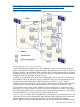
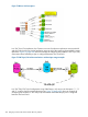


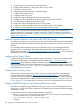

Figure 75 Three Data Center Architecture
An application is deployed in 3DC DR Solution, by configuring it at all three sites. The sites are
referred either as DC1 or DC2 or DC3 for an application based on their role. The primary site for
the application is where it is expected to run under normal circumstances and is also referred as
DC1 site for the application. The hot-standby site for the application is where it automatically fails
over to in case of a disaster in its DC1 site. This hot-standby site is also referred as DC2 site for
the application. An application must have its DC1 and DC2 sites within the Metrocluster. A
second-standby site (far site), where the recovery cluster is located is referred as DC3 site for the
application. In case of a disaster affecting the application’s DC1 and DC2 sites, the application
can be recovered at the recovery cluster in its DC3 site. The recovery of the application at DC3
site is automated, but must be manually triggered upon notification. For each application, a 3DC
replication using a set of device group pairs is configured to replicate the data across all its three
sites.
NOTE: DC1, DC2, and DC3 are application-specific roles of a site.
The subsequent sections describe how the applications are deployed using Tri-Link and Bi-Link
configurations in a 3DC DR Solution.
Tri-Link Configuration
In Tri-Link configuration, for each application, a 3DC replication using three device group pairs is
configured to replicate the data across all its three sites. as shown in Figure 76 (page 426).
Overview of 3DC DR Solution 425