
Designing Disaster Recovery Clusters using Metroclusters and Continentalclusters, Reprinted October 2011 (5900-1881)


The DGM provides the following functionalities:
• Sends a notification message upon the change in a device group status.
• Performs automatic resynchronization of the Continuous Access device group upon link
recovery.
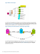
• In case of a Tri-Link configuration, it performs automatic resynchronization of the Delta Resync
pair upon some of the failures that result in data not being replicated over the active Continuous
Access Journal pair to the third data center (DC3).
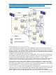
In the 3DC environment, where the device group state is not actively monitored, it may not be
apparent when the application data is not remotely protected for an extended period of time. For
example, there is a link failure between DC1 and DC2. If DGM is not configured, this link failure
may go unnoticed and this will cause data loss at DC2 upon DC1 failure. Similarly, for example,
if the data is being replicated from DC1 to DC2 and then from DC2 to DC3, and there is a link
failure between DC2 and DC3, it results in data not being replicated to DC3. The DGM identifies
link failure, notifies the user, and performs appropriate actions based on the monitor’s parameter
settings.
Configuring DGM is optional but strongly recommended. The DGM runs as a package service.
The user can configure the monitor's setting through the DGM specific parameters in the package
configuration file. Once the package has started the DGM, the monitor periodically checks the
status of the device pairs configured in the package. If there is a change in the status or if the
monitor is configured to notify after an interval of no status change, the monitor sends a notification
to the user via e-mail, syslog, and console. The notification message states the reason for the
notification, a timestamp, and the status of the device groups.
Infrastructure Requirements
Following are the infrastructure requirements for configuring any application in 3DC DR Solution:
• Ensure that the port number used by HP-UX Secure Shell is open for communication across
three data centers. Nodes in all the three data centers must be able to communicate over the
network.
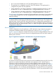
• The replication links must be available among the three P9000 or XP arrays if it is a 3DC
Tri-Link configuration. For 3DC Bi-Link configuration, the replication link must be available
between the P9000 or XP arrays located in the Metrocluster region, and the replication link
must be established between one of the P9000 or XP Disk Arrays located in the Metrocluster,
and the recovery cluster at the third site.
• In case of 3DC Tri-Link configuration using Delta Resync, remote command devices must be
created on each P9000 or XP array for the other two P9000 or XP arrays by using P9000 or
XP External Storage Software. For information on creating a remote command device, see the
HP StorageWorks P9000 External Storage for Open and Mainframe Systems User Guide or
HP Storage-Works XP24000/XP20000 External Storage Software User's Guide available at
http://bizsupport1.austin.hp.com/bizsupport/TechSupport/ProdSearch.jsp?
prod=HP%20StorageWorks.
Configuring an P9000 or XP 3DC DR Solution
After the hardware set up is completed for all three data centers including the infrastructure
requirements as specified in “Infrastructure Requirements” (page 429), the next step is the software
installation and configuration. The cluster software used in a 3DC DR Solution includes Serviceguard
clusters, Metrocluster with Continuous Access for P9000 and XP, Continentalclusters, and HP
StorageWorks RAID Manager.
Complete the following procedures to configure an application in a 3DC DR Solution:
1. Install the required software on all nodes in the 3DC DR Solution.
2. Configure the primary cluster (Metrocluster).
Infrastructure Requirements 429