HP 2012sa Modular Smart Array user guide Part number: 488320-004 First edition: January 2013
Legal and notice information © Copyright 2008, 2013 Hewlett-Packard Development Company, L.P. Hewlett-Packard Company makes no warranty of any kind with regard to this material, including, but not limited to, the implied warranties of merchantability and fitness for a particular purpose. Hewlett-Packard shall not be liable for errors contained herein or for incidental or consequential damages in connection with the furnishing, performance, or use of this material.
Contents About This Guide . . . . . . . . . . . . . . . . . . . . . . . . . . . . . . . . . . . . . . . . . . . . . . . . . . .7 Intended Audience . . . . . . . . . . . . . . . . . . . . . . . . . . . . . . . . . . . . . . . . . . . . . . . . . . .7 Prerequisites . . . . . . . . . . . . . . . . . . . . . . . . . . . . . . . . . . . . . . . . . . . . . . . . . . . . . . . .7 Document Conventions Rack Stability . . . . . . . . . . . . . . . . . . . . . . . . . . . . . . . . . . . . . . . . . . . . . .
Installation Checklist . . . . . . . . . . . . . . . . . . . . . . . . . . . . . . . . . . . . . . . . . . . . . . . . 27 Installing Enclosures Into a Rack Preparing the Rack . . . . . . . . . . . . . . . . . . . . . . . . . . . . . . . . . . . . . . . 28 . . . . . . . . . . . . . . . . . . . . . . . . . . . . . . . . . . . . . . . . . . . . . . 28 Assembling and Installing the Rackmount Bracket Kit Attaching the Ear Caps . . . . . . . . . . . . . . . . . . . . . . . . . . . . . . . . . . . . . . . .
. Troubleshooting . . . . . . . . . . . . . . . . . . . . . . . . . . . . . . . . . . . . . . . . . . . . . . . . . . . 53 Fault Isolation Methodology Gather Fault Information . . . . . . . . . . . . . . . . . . . . . . . . . . . . . . . . . . . . . . . . . . 53 . . . . . . . . . . . . . . . . . . . . . . . . . . . . . . . . . . . . . . . . . . 53 Determine Where the Fault Is Occurring Review the Event Logs Isolate the Fault . . . . . . . . . . . . . . . . . . . . . . . . . . . . . . 53 . . . . . .
A. Environmental Requirements and Specifications B. Regulatory Compliance and Safety Index 6 . . . . . . . . . . . . . . . . . . . . . . . . 71 . . . . . . . . . . . . . . . . . . . . . . . . . . . . . . . . . . . 77 . . . . . . . . . . . . . . . . . . . . . . . . . . . . . . . . . . . . . . . . . . . . . . . . . . . . . . . . . . . .
About This Guide Intended Audience This guide is intended for use by system administrators and information professionals who are experienced with the following: ■ Direct attach storage (DAS) or storage area network (SAN) management ■ Network administration ■ Network installation ■ Storage system installation and configuration, including installing an HP rack Prerequisites Prerequisites for installing and configuring this product include familiarity with: ■ Servers and computer networks ■ Host communicatio
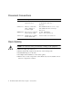
Document Conventions Typeface Meaning Examples AaBbCc123 Book title, new term, or emphasized word See the user guide. A virtual disk (vdisk) can .... You must ... AaBbCc123 Directory or file name, value, command, or on-screen output The default file name is store.logs. .The default user name is manage Type exit AaBbCc123 Text you type, contrasted with on-screen output # set password Enter new password: AaBbCc123 Variable text you replace Use the format user@domain.
HP Technical Support Telephone numbers for worldwide technical support are listed on the HP support website: http://www.hp.com/support/. Collect the following information before calling: Technical support registration number (if applicable) ■ Product serial numbers ■ Product model names and numbers ■ Applicable error messages ■ Operating system type and revision level ■ Detailed, specific questions ■ For continuous quality improvement, calls may be recorded or monitored.
Subscription Service HP strongly recommends that customers sign up online using the Subscriber's choice website: http://www.hp.com/go/e-updates. Subscribing to this service provides you with e-mail updates on the latest product enhancements, newest versions of drivers, and firmware documentation updates as well as instant access to numerous other product resources. HP Websites For other product information, see the following HP websites: ■ ■ ■ ■ ■ http://www.hp.com http://www.hp.com/go/storage http://www.
CH A P T E R 1 System Components The MSA2000 Family 2012sa Modular Smart Array and MSA2000 Drive Enclosure are high-performance storage solutions that combine outstanding performance with high reliability, availability, flexibility, and manageability. Supported configurations include a controller enclosure with or without attached drive enclosures. A controller enclosure can contain two controllers that interact and provide failover capability for the data path.
System Management Software Embedded management software includes a web-browser interface and the command-line interface described below. HP StorageWorks MSA2000 Family Storage Management Utility (SMU) SMU is the primary interface for configuring and managing the system. A web server resides in each controller module. SMU enables you to manage the system from a web browser that is properly configured and that can access a controller module through an Ethernet connection.
Hardware Components and LEDs This section describes the main hardware components of your storage system enclosures. Controller Enclosure Components and LEDs Table 1-1 describes the controller enclosure components.
Figure 1-1 shows the LEDs on the front of a controller enclosure. Enclosure ID Drive module LEDs (top to bottom) Fault/UID Online/activity Status LEDs (top to bottom): UID Fault ID Heartbeat Drive modules are numbered by column top to bottom: 0–2, 3–5, 6–8, 9–11 Figure 1-1 Controller Enclosure LEDs (Front View) Table 1-2 describes the LEDs on the front of a controller. For information about troubleshooting the system using LEDs, see “Troubleshooting” on page 53.
Table 1-3 describes the LEDs on the drive module. Table 1-3 Drive Module LED Combinations (Front) Online/Activity (green) Fault/UID (amber/blue) Description On Off The drive is online, but it is not currently active. Blinking irregularly Off The drive is active and operating normally. Off Amber, blinking regularly (1 Hz) Offline; the drive is not being accessed. A predictive failure alert may have been received for this device. Further investigation is required.
Figure 1-2 shows the ports and switches at the back of the controller enclosure. Power switch Host ports MUI (Service) port CLI port Ethernet port Expansion port Figure 1-2 Controller Ports and Switches (Back View) Table 1-4 describes the ports and switches on the back of the controller.
Figure 1-3 shows the LEDs at the back of the controller. AC Power Good Host link status Host link activity DC Voltage/Fan Fault/ Service Required Unit Locator OK to Remove Cache status Host activity OK Expansion port status Ethernet activity Fault/Service Required Ethernet link status Figure 1-3 Controller LEDs (Back View) Table 1-5 describes the LEDs on the back of the controller. For information about troubleshooting the system using LEDs, see “Troubleshooting” on page 53.
Table 1-5 Controller LEDs (Back) (Continued) Location Controller module Controller module Controller module Controller module Controller module 18 LED Unit Locator OK to Remove Fault/Service Required OK Cache status Color State Description White Off Normal operation. Blink Physically identifies the controller module. Off The controller module is not prepared for removal. On The controller module can be removed. On A fault has been detected or a service action is required.
Table 1-5 Controller LEDs (Back) (Continued) Location LED Color State Description Controller module Cache status Green Blink A Compact Flash flush or cache self-refresh is in progress. Indicates cache activity. • If the LED is blinking evenly, a cache flush is in progress. When a controller module loses power and write cache is dirty (contains data that has not been written to disk), the super-capacitor pack provides backup power to flush (copy) data from write cache to Compact Flash memory.
Table 1-5 Controller LEDs (Back) (Continued) Location LED Color State Description Controller module Ethernet activity Green Off The Ethernet link has no I/O activity. Blink The Ethernet link has I/O activity. Off The port is empty or the link is down. On The port link is up and connected.
The components and LEDs on the front of a drive enclosure are the same as on a controller enclosure; see Figure 1-1 and Table 1-2. Figure 1-4 shows the ports and switches at the back of the drive enclosure. Power switch SAS In port Service port SAS Out port Figure 1-4 Drive Enclosure Ports and Switches (Back View) Table 1-7 describes the ports and switches on the back of the drive enclosure.
Figure 1-5 shows the LEDs at the back of the drive enclosure. AC Power Good DC Voltage/Fan Fault/ Service Required SAS In port status Unit Locator SAS Out port status OK OK to Remove Fault/Service Required Figure 1-5 Drive Enclosure LEDs (Back View) Table 1-8 describes the LEDs on the back of the drive enclosure.
Table 1-8 Drive Enclosure LEDs (Back) (Continued) Location Expansion module Expansion module Expansion module LED Fault/Service Required OK SAS Out port status Color State Description Amber On A fault has been detected or a service action is required. Blink Indicates a hardware-controlled power up or a cache flush or restore error. Off Expansion module is not OK. On Expansion module is operating normally. Blink System is booting. Off The port is empty or the link is down.
HP 2012sa Modular Smart Array user guide • January 2013
CH A P T E R 2 Installing and Cabling Enclosures This chapter describes how to install and cable enclosures.
Safety Precautions For your protection, observe the following safety precautions when setting up your equipment: ■ Install the system in accordance with the local safety codes and regulations at the facility site. Follow all cautions and instructions marked on the equipment. ■ Ensure that the voltage and frequency of your power source match the voltage and frequency inscribed on the equipment’s electrical rating label. ■ Never push objects of any kind through openings in the equipment.
Installation Checklist Table 2-1 outlines the steps required to install the enclosures and initially configure the system. To ensure a successful installation, perform the tasks in the order they are presented. Table 2-1 Installation Checklist Step Installation Task Where to Find Procedure 1. Prepare the rack for installation. “Preparing the Rack” on page 28 2. Assemble the rackmount bracket kit and install the controller enclosure and optional drive enclosures in the rack.
Installing Enclosures Into a Rack This section describes how to install the enclosures into a standard 19-inch rack cabinet with a 28 to 36-inch (71.12 to 91.44-cm) depth. Tip – To help you correctly identify the screws, keep all hardware items in plastic bags until you are ready to use them. Preparing the Rack Before installing enclosures in a rack cabinet, ensure the rack is installed according to its installation instructions and that the installation complies with local safety codes. 1.
Figure 2-1 provides a visual overview of the rackmount kit assembly components and corresponds to the steps that follow.
Use the following procedure and refer to Figure 2-1 to install each enclosure into the rack. Note – If the rackmount bracket kit you are installing includes assembly instructions, use them in place of the instructions in this guide. When positioning an enclosure in the rack, do not block the air vents at the front or back of the enclosure.
Figure 2-2 Side Bracket With Alignment Marks b. On one side, insert the first two screws through the side bracket slots above and below the alignment mark into the rear-most threaded holes in the enclosure. For example, to mount the enclosure in a 28-inch deep rack, position the side bracket so that the 28-inch alignment mark is aligned with the rear-most threaded holes in the enclosure. c.
Attaching the Ear Caps The plastic ear caps are snap-on parts that require some care when attaching or removing them. After the enclosure has been installed in the rack cabinet, attach the ear caps, which are located in a plastic bag included in the controller and drive enclosure packages. 1. Remove the ear caps from the plastic package. 2. As you attach each ear cap, hold it so that its indent is closest to the chassis. Indent Left ear cap Indent Right ear cap Figure 2-3 Attaching Ear Caps 3.
Connecting Controller and Drive Enclosures Use the supplied SAS cables to connect a controller enclosure to up to three drive enclosures. Figure 2-4 and Figure 2-5 show the recommended fault-tolerant cabling patterns. In an enclosure, the upper module is designated A and the lower module is designated B. When connecting multiple drive enclosures, use reverse cabling to ensure the highest level of fault tolerance.
Controller A Controller B In Out 1A In Out 1B In Out 2A In Out 2B In Out 3A In Out 3B Figure 2-5 Fault-Tolerant Cabling Connections Between One Controller Enclosure and Up to Three Drive Enclosures 34 HP 2012sa Modular Smart Array user guide • January 2013
Controller A Controller B In Out 1A In Out 1B In Out 2A In Out 2B In Out In Out 3A 3B Figure 2-6 Non-Fault-Tolerant Cabling Connections Between One Controller and Up to Three Drive Enclosures Chapter 2 Installing and Cabling Enclosures 35
Connecting AC Power Use this procedure to connect AC power to the enclosures. 1. Verify that both power switches are off. 2. Using the AC power cords, for each enclosure, connect one power-and-cooling module to one power source in the rack, and the other power-and cooling-module to a separate power source in the rack. 3. Connect the primary power cords from the rack to separate external power sources. Power on the system as described in the following section.
Testing the Enclosure Connections Use this procedure to power on the newly installed system. 1. Press the power switches at the back of each drive enclosure to the On position. This ensures that the disks in the enclosures have enough time to completely spin up before being scanned by the RAID modules in the controller enclosure. While enclosures power up, their LEDs blink.
When powering on the system, make sure to power up the enclosures and associated data host in the following order: 1. Drive enclosures first 2. Controller enclosure next 3. Data hosts last (if they are powered down for maintenance purposes) Obtaining IP Values for Your Storage System To obtain the IP values for your system: 1. Look in the DCHP server’s address for the two IP addresses assigned to an “HP StorageWorks MSA2000 Family” storage device. 2.
CH A P T E R 3 Connecting Hosts This chapter describes how to connect data and management hosts to controller enclosures.
Installing the MSA2000 Family SES Driver for Microsoft Windows Hosts Installing the MSA2000 Family SCSI Enclosure Services (SES) driver prevents Microsoft Windows hosts from displaying the Found New Hardware Wizard when the storage system is discovered. 1. Download MSA2000 Family SCSI Enclosure Services (SES) driver package msa2000-ses-version.zip from the http://www.hp.com/go/msa. Select MSA SAN Arrays, select your product, and go to Related products. 2.
CH A P T E R 4 Configuring a System for the First Time This chapter describes how to perform first-time configuration on the storage system using HP StorageWorks MSA2000 Family Storage Management Utility (SMU), which is the primary interface for configuring and managing the system. It also describes how to perform basic storage configuration to verify that your system is working.
Setting Management Port IP Addresses Using the CLI Note – If you used DHCP to set the IP addresses, you do not have to set them using the CLI as described in this section. Ethernet Management ports on controller module A and controller module B are configured with the following default values: ■ Management Port IP Address: 10.0.0.2 (controller A), 10.0.0.3 (controller B) ■ IP Subnet Mask: 255.255.255.0 ■ Gateway IP Address: 10.0.0.
Your package contents include a micro-DB9-to-DB9 serial cable. If necessary, use a DB9-to-DB25 adapter (not included) for connecting the serial cable to a DB25 serial port on the host computer. 3. Start and configure a terminal emulator, such as HyperTerminal or VT-100, using the display settings in Table 4-1 and the connection settings in Table 4-2.
4. In the terminal emulator, connect to controller A. 5. Press Enter to display the CLI prompt (#). 6.
As shown in the following example, network parameters, including the IP address, gateway address, and subnet mask are displayed for each controller. Network Parameters Controller A -------------------------------IP Address : 192.168.0.10 Gateway : 192.168.0.1 Subnet Mask : 255.255.0.0 MAC Address : 00:00:FF:D5:01:4D Addressing Mode : Manual Network Parameters Controller B -------------------------------IP Address : 192.168.0.11 Gateway : 192.168.0.1 Subnet Mask : 255.255.0.
Configuring Your Web Browser for SMU Before using SMU to perform remaining steps, ensure that your web browser is properly configured according to the following guidelines: ■ Use one of the following browsers: ■ Microsoft Internet Explorer 5.5 or later ■ Mozilla Firefox 1.0.7 or later ■ Because SMU uses popup windows to indicate the progress of user-requested tasks, disable any browser features or tools that block popup windows. ■ For optimal performance, set your browser to use stored (cached) web pages.
Updating Firmware After installing the hardware and powering up the enclosure for the first time, be sure to verify that the controllers and drive enclosures have the latest firmware. SMU enables you to view the software, hardware, and other version information for each controller and the enclosures. To view controller version information, select Monitor > Status > Advanced Settings > Controller Versions.
If no NTP server is present, the date and time are maintained as if NTP had not been enabled. To manually set the system date and time: 1. Select Manage > General Config > Set Date/Time. 2. In the Set System Date panel, select the current month, day, and year. 3. In the Set System Time panel, type time values using a 24-hour clock (where hour 8 represents 8 a.m. and hour 20 represents 8 p.m.) and select the proper time zone. 4. Click Change Date/Time. To obtain the date and time from an NTP server: 1.
To create both virtual disks: 1. Select Manage > Virtual Disk Config > Create A Vdisk. 2. Select Manual Virtual Disk Creation. 3. Type a name for the virtual disk. The name is case-sensitive and can include 17 characters. Allowed characters include letters, numbers, hyphens, underscores, and spaces. 4. Select RAID 5 – Parity RAID, Parity Distributed. 5. Click Create New Virtual Disk. 6. Select five drives of the same size and type (all SAS or all SATA). 7.
Mapping a Volume to a Host To enable a data host to access a volume you created, you must map the volume to the host. The port World Wide Name (WWN) of each host connected to the system is automatically added to the system’s global host port list. Before mapping a data host to a volume you must identify the data host’s port WWN and a LUN that the host is not using. To map a data host to a volume: 1. Select Manage > Volume Management > Volume Mapping > Map Hosts To Volume.
If the above tests succeed, your system is ready for use. 3. Optionally, unmount the volume and delete the vdisks created for test. Logging Out of SMU If you do not log out of SMU when you have finished using it, other manage users cannot log in to the same controller module and your IP address stays logged in for 30 minutes (the default auto-logout timeout setting). To log out of SMU: 1. Click Log Off at the bottom of the menu. The Log Off page is displayed. 2. Click Log Off.
HP 2012sa Modular Smart Array user guide • January 2013
CH A P T E R 5 Troubleshooting Fault Isolation Methodology The MSA2000 Family storage system provides many ways to isolate faults within the system. This section presents the basic methodology used to locate faults and the associated FRUs.
When a fault occurs, the Fault ID status LED on an enclosure’s right ear (see Figure 1-1) illuminates. Check the LEDs on the back of the enclosure to narrow the fault to a FRU, connection, or both. The LEDs also help you identify the location of a FRU reporting a fault. Use SMU to verify any faults found while viewing the LEDs. SMU is also a good tool to use in determining where the fault is occurring if the LEDs cannot be viewed due to the location of the system.
If the Enclosure Does Not Initialize It may take up to two minutes for the enclosures to initialize. If the enclosure does not initialize: ■ Perform a rescan. ■ Power cycle the system. ■ Make sure the power cord is properly connected and check the power source that it is connected to. ■ Check the event log for errors. Correcting Enclosure IDs When installing a system with drive enclosures attached, the enclosure IDs might not agree with the physical cabling order.
Using System LEDs to Diagnose Problems This section describes possible reasons and actions to take when an LED indicates a fault condition. See “System Components” on page 11 for descriptions of all LED statuses. Is the front panel Fault ID amber? Answer Possible Reasons Actions No System functioning properly. No action required. Yes A fault condition exits. • Check the LEDs on the back of the controller to narrow the fault to a FRU, connection, or both.
Is the controller back panel Fault/Service Required LED amber? Answer Possible Reasons Actions No System functioning properly. No action required. Yes (blinking) One of the following errors occurred: • Hardware-controlled powerup error • Cache flush error • Cache self-refresh error • Restart this controller from the other controller using SMU or the CLI. • Remove the controller and reinsert it. • Contact an authorized service provider for assistance. • Replace the controller.
Is the drive module Fault/UID LED blinking amber? 58 Answer Possible Reasons Actions No, but the Online/Activity LED is blinking The drive is rebuilding. No action required. Note: Do not remove a drive that is rebuilding. Removing a drive may terminate the current operation and cause data loss. Yes, and the Online/Activity LED is off The drive is offline. A predictive failure alert may have been received for this device. • Check the event log for specific information regarding the fault.
Is a connected port’s Host Link Status LED off? Answer Possible Reasons Actions No System functioning properly. No action required. Yes The link is down. • • • • Check cable connections. Reseat cables. Replace cables. In SMU, review the event logs for indicators of a specific fault in a host data path component. Is a connected port’s Expansion Port status LED off? Answer Possible Reasons Actions No System functioning properly. No action required. Yes The link is down.
Is a connected port’s Ethernet link status LED off? Answer Possible Reasons Actions No System functioning properly. No action required. Yes The link is down. Use standard networking troubleshooting procedures to isolate faults on the network. Is the power-and-cooling module AC Power Good LED off? 60 Answer Possible Reasons Actions No System functioning properly. No action required. Yes The module is not receiving adequate power.
Is the power-and-cooling module DC Voltage/Fan Fault/Service Required LED amber? Answer Possible Reasons Actions No System functioning properly. No action required. Yes The power supply unit or a fan is operating at an unacceptable voltage/RPM level, or has failed. When isolating faults in the powerand-cooling module, remember that the fans in both modules receive power through a common bus on the midplane, so if a power supply unit fails, the fans continue to operate normally.
Is the drive enclosure Fault/Service Required LED amber? 62 Answer Possible Reasons Actions No System functioning properly. No action required. Yes (blinking) One of the following errors occurred: • Hardware-controlled powerup error • Cache flush error • Cache self-refresh error • Check the event log for specific information regarding the fault. • Isolate the fault. • Contact an authorized service provider for assistance. • Replace if necessary. Yes A fault occurred.
Isolating a Host-Side Connection Fault During normal operation, when a controller module host port is connected to a data host, the port’s host link status LED and host link activity LED are green. If there is I/O activity, the host activity LED blinks green. If data hosts are having trouble accessing the storage system, and you cannot locate a specific fault or cannot access the event logs, use the following procedure. This procedure requires scheduled downtime.
Is the host link status LED on? ■ Yes – You have isolated the fault to the HBA. Replace the HBA. ■ No – It is likely that the controller module needs to be replaced. 6. Move the cable back to its original port. Is the host link status LED on? ■ No – The controller module’s port has failed. Replace the controller module. ■ Yes – Monitor the connection for a period of time. It may be an intermittent problem, which can occur with damaged cables and HBAs.
4. Move the expansion cable to a port on the RAID enclosure with a known good link status. This step isolates the problem to the expansion cable or to the controller module’s expansion port. Is the expansion port status LED on? ■ Yes – You now know that the expansion cable is good. Return cable to the original port. If the expansion port status LED remains off, you have isolated the fault to the controller module’s expansion port. Replace the controller module. ■ No – Proceed to the next step. 5.
Resolving Voltage and Temperature Warnings 1. Check that all of the fans are working by making sure each power-and-cooling module’s DC Voltage/Fan Fault/Service Required LED is off or by using SMU to check the Status Summary page (select Monitor > Status > Status Summary). 2. Make sure that all modules are fully seated in their slots and that their latches are locked. 3. Make sure that no slots are left open for more than two minutes.
Power Supply Sensors Each enclosure has two fully redundant power-and-cooling modules with loadsharing capabilities. The power supply sensors described in the following table monitor the voltage, temperature, and fans in each power-and-cooling module. If the power supply sensors report a voltage that is under or over the threshold, check the input voltage.
Temperature Sensors Extreme high and low temperatures can cause significant damage if they go unnoticed. Each controller module has six temperature sensors. Of these, if the CPU or FPGA temperature reaches a shutdown value, the controller module is automatically shut down. Each power-and-cooling module has one temperature sensor. When a temperature fault is reported, it must be remedied as quickly as possible to avoid system damage. This can be done by warming or cooling the installation location.
To view the controller enclosure’s temperature status, in SMU, as an Advanced Manage user: ● Select Monitor > Status > Advanced Settings > Temperature Status. Power-and-Cooling Module Voltage Sensors Power supply voltage sensors ensure that an enclosure’s power supply voltage is within normal ranges. There are three voltage sensors per power-and-cooling module. Table 5-5 Voltage Sensor Descriptions Sensor Event/Fault ID LED Condition Power Supply 1 Voltage, 12V < 11.00V > 13.
HP 2012sa Modular Smart Array user guide • January 2013
APPENDIX A Environmental Requirements and Specifications Safety Requirements Install the system in accordance with the local safety codes and regulations at the facility site. Follow all cautions and instructions marked on the equipment. Site Requirements and Guidelines The following sections provide requirements and guidelines that you must address when preparing your site for the installation.
■ ■ Site wiring must include an earth ground connection to the AC power source. The supply conductors and power distribution boxes (or equivalent metal enclosure) must be grounded at both ends. Power circuits and associated circuit breakers must provide sufficient power and overload protection.
Electrical Guidelines ■ ■ ■ These enclosures work with single-phase power systems having an earth ground connection. To reduce the risk of electric shock, do not plug an enclosure into any other type of power system. Contact your facilities manager or a qualified electrician if you are not sure what type of power is supplied to your building. Enclosures are shipped with a grounding-type (three-wire) power cord. To reduce the risk of electric shock, always plug the cord into a grounded power outlet.
Management Host Requirements A local management host with at least one serial port connection is recommended for the initial installation and configuration of a controller enclosure. After you configure one or both of the controller modules with an Internet Protocol (IP) address, you then use a remote management host on an Ethernet network to configure, manage, and monitor.
Table A-2 Rackmount Enclosure Weights Specification Rackmount 2012sa Modular Smart Array (12 drives) • SAS drives • SATA drives 64.5 lb (29.3 kg) 65.5 lb (29.8 kg) MSA2000 Drive Enclosure (12 drives) • SAS drives • SATA drives 62 lb (28.2 kg) 63 lb (28.6 kg) Environmental Requirements Table A-3 Operating Environmental Specifications Specification Range Altitude To 9842 feet (3000 meters), derate 35.
Electrical Requirements Site Wiring and Power Requirements Each enclosure has two power and cooling modules for redundancy. If full redundancy is required, use a separate power source for each module. The AC power supply unit in each power and cooling module is auto-ranging and is automatically configured to an input voltage range from 88–264 VAC with an input frequency of 47–63 Hz. The power and cooling modules meet standard voltage requirements for both U.S. and international operation.
APPENDIX B Regulatory Compliance and Safety Regulatory Compliance Federal Communications Commission Notice Part 15 of the Federal Communications Commission (FCC) Rules and Regulations has established Radio Frequency (RF) emission limits to provide an interferencefree radio frequency spectrum. Many electronic devices, including computers, generate RF energy incidental to their intended function and are, therefore, covered by these rules.
instructions, may cause harmful interference to radio communications. Operation of this equipment in a residential area is likely to cause harmful interference, in which case the user will be required to correct the interference at personal expense. Class B Equipment This equipment has been tested and found to comply with the limits for a Class B digital device, pursuant to Part 15 of the FCC Rules.
To identify this product, refer to the part, Regulatory Model Number, or product number found on the product. Modifications The FCC requires the user to be notified that any changes or modifications made to this device that are not expressly approved by Hewlett-Packard Company may void the user's authority to operate the equipment. Cables Connections to this device must be made with shielded cables with metallic RFI/EMI connector hoods in order to maintain compliance with FCC Rules and Regulations.
Regulatory compliance label Figure 5-1 Regulatory Compliance Label Location Laser Device All HP systems equipped with a laser device comply with safety standards, including International Electrotechnical Commission (IEC) 825. With specific regard to the laser, the equipment complies with laser product performance standards set by government agencies as a Class 1 laser product. The product does not emit hazardous light.
Certification and Classification Information This product contains a laser internal to the fiber optic (FO) transceiver for connection to the Fibre Channel communications port. In the USA, the FO transceiver is certified as a Class 1 laser product conforming to the requirements contained in the Department of Health and Human Services (DHHS) regulation 21 CFR, Subchapter J. A label on the plastic FO transceiver housing indicates the certification.
Class B Equipment This Class B digital apparatus meets all requirements of the Canadian InterferenceCausing Equipment Regulations. Cet appareil numérique de la classe B respecte toutes les exigences du Règlement sur le matériel brouilleur du Canada.
Japanese Notice Korean Notices Appendix B Regulatory Compliance and Safety 83
Safety Battery Replacement Notice Your computer is equipped with a lithium manganese dioxide, a vanadium pentoxide, or an alkaline internal battery or battery pack. There is a danger of explosion and risk of personal injury if the battery is incorrectly replaced or mistreated. Replacement is to be done by an HP authorized service provider using the HP spare part designated for this product.
Power Cords The power cord set must meet the requirements for use in the country where the product was purchased. If the product is to be used in another country, purchase a power cord that is approved for use in that country. The power cord must be rated for the product and for the voltage and current marked on the product electrical ratings label. The voltage and current rating of the cord should be greater than the voltage and current rating marked on the product.
■ ■ ■ Place parts on a grounded surface before removing them from their containers. Avoid touching pins, leads, or circuitry. Always be properly grounded when touching a static-sensitive component or assembly (see “Grounding Methods” on page 86). Grounding Methods There are several methods for grounding. Use one or more of the following methods when handling or installing electrostatic-sensitive parts: ■ Use a wrist strap connected by a ground cord to a grounded workstation or computer chassis.
Waste Electrical and Electronic Equipment Directive Czechoslovakian Notice Danish Notice Bortskaffelse af affald fra husstande i den Europæiske Union Hvis produktet eller dets emballage er forsynet med dette symbol, angiver det, at produktet ikke må bortskaffes med andet almindeligt husholdningsaffald. I stedet er det dit ansvar at bortskaffe kasseret udstyr ved at aflevere det på den kommunale genbrugsstation, der forestår genvinding af kasseret elektrisk og elektronisk udstyr.
Dutch Notice Verwijdering van afgedankte apparatuur door privé-gebruikers in de Europese Unie Dit symbool op het product of de verpakking geeft aan dat dit product niet mag worden gedeponeerd bij het normale huishoudelijke afval. U bent zelf verantwoordelijk voor het inleveren van uw afgedankte apparatuur bij een inzamelingspunt voor het recyclen van oude elektrische en elektronische apparatuur.
Estonian Notice Seadmete jäätmete kõrvaldamine eramajapidamistes Euroopa Liidus See tootel või selle pakendil olev sümbol näitab, et kõnealust toodet ei tohi koos teiste majapidamisjäätmetega kõrvaldada. Teie kohus on oma seadmete jäätmed kõrvaldada, viies need elektri- ja elektroonikaseadmete jäätmete ringlussevõtmiseks selleks ettenähtud kogumispunkti.
French Notice Élimination des appareils mis au rebut par les ménages dans l'Union européenne Le symbole apposé sur ce produit ou sur son emballage indique que ce produit ne doit pas être jeté avec les déchets ménagers ordinaires. Il est de votre responsabilité de mettre au rebut vos appareils en les déposant dans les centres de collecte publique désignés pour le recyclage des équipements électriques et électroniques.
Greek Notice . , . . , , . Hungarian Notice Készülékek magánháztartásban történ selejtezése az Európai Unió területén A készüléken, illetve a készülék csomagolásán látható azonos szimbólum annak jelzésére szolgál, hogy a készülék a selejtezés során az egyéb háztartási hulladéktól eltér módon kezelend . A vásárló a hulladékká vált készüléket köteles a kijelölt gy jt helyre szállítani az elektromos és elektronikai készülékek újrahasznosítása céljából.
Italian Notice Smaltimento delle apparecchiature da parte di privati nel territorio dell'Unione Europea Questo simbolo presente sul prodotto o sulla sua confezione indica che il prodotto non può essere smaltito insieme ai rifiuti domestici. È responsabilità dell'utente smaltire le apparecchiature consegnandole presso un punto di raccolta designato al riciclo e allo smaltimento di apparecchiature elettriche ed elettroniche.
Lihuanian Notice Nolietotu iek rtu izn cin šanas noteikumi lietot jiem Eiropas Savien bas priv taj s m jsaimniec b s Š ds simbols uz izstr d juma vai uz t iesai ojuma nor da, ka šo izstr d jumu nedr kst izmest kop ar citiem sadz ves atkritumiem. J s atbildat par to, lai nolietot s iek rtas tiktu nodotas speci li iek rtotos punktos, kas paredz ti izmantoto elektrisko un elektronisko iek rtu sav kšanai otrreiz jai p rstr dei.
Portuguese Notice Descarte de Lixo Elétrico na Comunidade Européia Este símbolo encontrado no produto ou na embalagem indica que o produto não deve ser descartado no lixo doméstico comum. É responsabilidade do cliente descartar o material usado (lixo elétrico), encaminhando-o para um ponto de coleta para reciclagem.
Slovenian Notice Spanish Notice Eliminación de residuos de equipos eléctricos y electrónicos por parte de usuarios particulares en la Unión Europea Este símbolo en el producto o en su envase indica que no debe eliminarse junto con los desperdicios generales de la casa. Es responsabilidad del usuario eliminar los residuos de este tipo depositándolos en un "punto limpio" para el reciclado de residuos eléctricos y electrónicos.
Swedish Notice Bortskaffande av avfallsprodukter från användare i privathushåll inom Europeiska Unionen Om den här symbolen visas på produkten eller förpackningen betyder det att produkten inte får slängas på samma ställe som hushållssopor. I stället är det ditt ansvar att bortskaffa avfallet genom att överlämna det till ett uppsamlingsställe avsett för återvinning av avfall från elektriska och elektroniska produkter.
Index A accessing SMU, 46 the CLI, 42 accumulators, 84 Avis Canadien, regulatory compliance notice, 81 B batteries recycling or disposal, 84 replacement notice, 84 Taiwan EPA recycling and disposal, 84 boot straps, using, 86 BSMI, regulatory compliance notice, 82 C cables FCC compliance statement, 74, 79 shielded, 74, 79 cabling routing requirements, 73 Canada, regulatory compliance notice, 81 certification and classification information, laser, 81 Class A equipment, Canadian compliance statement, 81 Clas
D data hosts connecting to controller enclosures mapping to volumes, 50 system requirements, 39 date and time, setting, 47 declaration of conformity, 78 DHCP obtaining IP addresses, 38 dimensions, 74 direct attach configurations, 40 disposal waste equipment for EU private households, 88 disposal, battery, 84 disposal, Taiwan EPA battery, 84 dissipating floor mats, 86 drive enclosures components, 20 connecting to controller enclosures, 33 connecting to other drive enclosures, 33 LEDs Fault/Service Required,
H heartbeat LED, 14 heel straps, using, 86 help, obtaining, 10 hosts, See data hosts HP address for FCC questions, 78 series number, 79 telephone number FCC questions, 78 humidity operating range, 75 HyperTerminal settings, See terminal emulator I cache status, 18, 19 DC Voltage/Fan Fault/Service Required, 17, 22 drive modules, 15 Enclosure ID, 14 Ethernet activity, 20 Ethernet link status, 19 expansion port status, 20 Fault/Service Required, 18, 23 heartbeat, 14 host activity, 19 host link status, 17 OK,
connecting AC, 36 power cord compliance notice, 85 current rating, 85 replacement, 85 set, 85 voltage rating, 85 power cord requirements, 76 power-and-cooling modules LEDs, 16 AC Power Good, 17, 22 DC Voltage/Fan Fault/Service Required, 17, 22 power switches, 21 voltage sensor descriptions, 69 preventing electrostatic damage, 85 R racks preparing, 28 recycling, battery, 84 recycling, Taiwan EPA battery, 84 regulatory compliance information number, 79 notices BSMI, 82 Canada, 81 Class A, 77 Class B, 78 Euro
terminal emulator connection settings, 43 display settings, 43 toe straps, using, 86 tools required for installation, 25 tools, conductive type, 86 troubleshooting, 64 correcting enclosure IDs, 55 using system LEDs, 56 U UID LED, 14 Unit identification (UID) LED, 14 V ventilation requirements, 73 vibration operating range, 75 virtual disks creating, 48 viewing status, 50 voltage compliance rating, 85 volumes mapping data hosts, 50 verifying, 50 W warnings lasers, radiation, 80 waste equipment disposal fo
HP 2012sa Modular Smart Array user guide • January 2013