HP Smart Array Controllers for HP ProLiant Servers User Guide Abstract This document includes feature, installation, and configuration information about HP Smart Array Controllers and is for the person who installs, administers, and troubleshoots servers and storage systems. HP assumes you are qualified in the servicing of computer equipment and trained in recognizing hazards in products with hazardous energy levels.
© Copyright 2008, 2012 Hewlett-Packard Development Company, L.P. The information contained herein is subject to change without notice. The only warranties for HP products and services are set forth in the express warranty statements accompanying such products and services. Nothing herein should be construed as constituting an additional warranty. HP shall not be liable for technical or editorial errors or omissions contained herein. Microsoft® and Windows® are U.S.
Contents Component identification ............................................................................................................... 6 Controller components ............................................................................................................................... 6 P212 components............................................................................................................................ 6 P222 components.......................................................
P700m, P711m, P712m, and P721m specifications .......................................................................... 35 P800, P812, and P822 specifications .............................................................................................. 35 Battery pack service life ........................................................................................................................... 36 Installation and configuration .....................................................................
Moving drives and arrays ........................................................................................................................ 86 Adding drives ......................................................................................................................................... 87 Electrostatic discharge ................................................................................................................. 89 Preventing electrostatic discharge ...............................
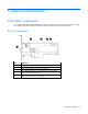
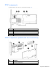
Component identification Controller components For cabling configuration and troubleshooting purposes, connector names are silk-screened on the controller. For connector and other component locations, see the appropriate controller-specific section. P212 components Item Description 1 Port 1E (Mini-SAS 4x connector) 2 Port 2I (Mini-SAS 4x connector) 3 Cache module (also known as array accelerator) 4 Status LEDs (runtime LEDs). For more information, see "Controller board runtime LEDs (on page 16).
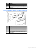
P222 components For LED locations and status, see "P222 LEDs (on page 19).
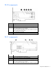
Item Description 3 Cache module connectors 4 Runtime LEDs. See "Controller board runtime LEDs (on page 16)." 5 Cache module (also known as array accelerator), showing the connector for the cable to an optional battery pack that upgrades the cache to BBWC P400 components (model with back connectors) Item Description 1 Cache module connectors 2 Port 1I (SAS 4x connector) 3 Runtime LEDs. See "Controller board runtime LEDs (on page 16).
P410 components Item Description 1 Cache module (also known as array accelerator) 2 Runtime LEDs. See "Controller board runtime LEDs (on page 16)." 3 (On rear of cache) Connector for the cable to an optional cache battery that upgrades the cache to BBWC (Not shown) In place of the BBWC option, the controller can support a FBWC module and capacitor pack.
Item Description FBWC module and capacitor pack. P420 components For LED locations and status, see "P420 LEDs (on page 19).
P421 components For LED locations and status, see "P421 LEDs (on page 20).
Item Description 3 Cache module (also known as array accelerator), showing the connector for the cable to an optional battery pack that upgrades the cache to BBWC P700m components Item Description 1 Runtime LEDs. See "Controller board runtime LEDs (on page 16)." 2 Connector (not used on HP ProLiant servers) 3 Cache module (also known as array accelerator) 4 Connector for the cable to an optional cache battery that upgrades the cache to BBWC. This connector is absent on some P700m models.
P711m components Item Description 1 Mezzanine connector 2 Runtime LED. See "Controller board runtime LEDs (on page 16)." 3 Cache module P712m components Item Description 1 Mezzanine connector 2 Runtime LED. See "Controller board runtime LEDs (on page 16).
Item Description 5 Cache module (not available on all models) P721m components For LED locations and status, see "P721m LEDs (on page 23).
Item Description 1 Ports 1E and 2E (Mini-SAS 4x connectors) 2 Heartbeat LED (flashes green when operating normally and amber if the board has failed) 3 Activity LED for external ports 4 Port 3I (Mini-SAS 4x connector) 5 Port 4I (Mini-SAS 4x connector) 6 Cache module (also known as array accelerator) 7 (Optional) Batteries for cache module Two batteries are normally sufficient, but you can add a third battery to provide extra security against loss of system power.
P822 components Item Description 1 Ports 1E, 2E, 3E, and 4E (Mini-SAS 4x connectors) 2 Port 5I (Mini-SAS 4x connector) 3 Port 6I (Mini-SAS 4x connector) 4 Cache module 5 Capacitor pack connector for cache module Controller board runtime LEDs Immediately after you power up the server, the controller runtime LEDs illuminate briefly in a predetermined pattern as part of the POST sequence.
P212, P410, and P411 LEDs LED ID Color Name Comments 1 Amber DS9: System Error The controller ASIC has locked up and cannot process any commands. 2 Green DS8: Idle Task This LED, together with the Gas Pedal LED (next item), indicates the amount of controller CPU activity. For more information, see the following table. 3 Green DS7: Gas Pedal This LED, together with the Idle Task LED (previous item), indicates the amount of controller activity. For more information, see the following table.
E500 and P400 LEDs LED ID Color Name Comments 1 Amber CR14: Controller Lockup The controller ASIC has locked up and cannot process any commands. 2 Amber CR13: Drive Failure To determine which drive has failed, check the Fault LED of each physical drive connected to the controller. 3 Green CR3: Activity Port 2E on the E500, or port 2I on the P400, is active. 4 Green CR8: Activity Port 1E on the E500, or port 1I on the P400, is active.
P222 LEDs Item Color Name Interpretation 1 Green Heartbeat When the controller is in good health, this LED flashes at 1 Hz. During power up, this LED is solid for up to 2 seconds. 2 Red Fault When an error occurs, this LED is on. During power up, this LED is solid for up to 2 seconds. 3 Amber Debug On = Controller is in reset. Off = Controller is in an idle or runtime state. Flashing 5 Hz = Controller and cache are performing a backup.
Item Color Name Interpretation Off = Controller is in an idle or runtime state. Flashing 5 Hz = Controller and cache are performing a backup. 2 Red Fault When an error occurs, this LED is on. During power up, this LED is solid for up to 2 seconds. 3 Green Heartbeat When the controller is in good health, this LED flashes at 1 Hz. During power up, this LED is solid for up to 2 seconds.
P700m LEDs LED ID Color Name Comments 1 Amber CR10: Thermal Alert This LED is not used. 2 Amber CR9: System Error The controller ASIC has locked up and cannot process any commands. 3 Amber CR1: Diagnostics Error One of the server diagnostics utilities has detected a controller error. 4 Amber CR2: Drive Failure To determine which drive has failed, check the Fault LED of each physical drive connected to the controller. 5 Green CR3: Activity Port 2 is active.
P711m LED Name: Controller heartbeat LED (CR6) Status: Flashes every 2 seconds = The controller is functioning properly. P712m LED Name: Controller heartbeat LED (CR6) Status: Flashes every 2 seconds = The controller is functioning properly.
P721m LEDs Color Name Interpretation Green Heartbeat When the controller is in good health, this LED flashes at 1 Hz. During power up, this LED is solid for up to 2 seconds. Amber Fault When an error occurs, this LED is on. During power up, this LED is solid for up to 2 seconds.
LED ID Color Name Comments 1 Green CR502: Expander Heartbeat This LED flashes every two seconds during normal operation. If the LED glows steadily, the expander cannot function due to an internal problem. If the LED flashes twice per second, the expander cannot function because the NVRAM is corrupt. 2 Amber CR510: System Error The controller ASIC has locked up and cannot process any commands.
P812 LEDs Item Color Name Comments 1 Green CR76: Idle Task This LED, together with the Gas Pedal LED (following item), indicates the amount of controller CPU activity. For more information, see the following table. 2 Green CR75: Gas Pedal This LED, together with the Idle Task LED (previous item), indicates the amount of controller CPU activity. For more information, see the following table. 3 Green CR74: Heartbeat When the controller is in good health, this LED flashes every 2 seconds.
P822 LEDs Item Color Name Interpretation 1 Green Heartbeat When the controller is in good health, this LED flashes at 1 Hz. During power up, this LED is solid for up to 2 seconds. 2 Red Fault When an error occurs, this LED is on. During power up, this LED is solid for up to 2 seconds. 3 Amber Debug On = Controller is in reset. Off = Controller is in an idle or runtime state. Flashing 5 Hz = Controller and cache are performing a backup.
1 Green LED 2 Amber LED Interpretation Off On A backup is in progress. Flashing (1 Hz) On A restore is in progress. Flashing (1 Hz) Off The capacitor pack is charging. On Off The capacitor pack has completed charging. Flashing (2 Hz) Alternating with amber LED Flashing (2 Hz) Alternating with green LED One of the following conditions exists: On On The flash code image failed to load. Off Off The flash code is corrupt. • • The charging process has timed out.
1 - Amber 2 - Green 3 - Green Interpretation Flashing 1 Hz On Off An overtemperature condition exists. Flashing 2 Hz Flashing 2 Hz Off The capacitor pack is not attached. Flashing 2 Hz Flashing 2 Hz On The capacitor has been charging for 10 minutes, but has not reached sufficient charge to perform a full backup. On On Off The current backup is complete, but power fluctuations occurred during the backup. On On On The cache module microcontroller has failed.
LED3 pattern LED4 pattern Interpretation Off Flashing (2 Hz) The system is powered down, and the cache contains data that has not yet been written to the drives. Restore system power as soon as possible to prevent data loss. Data preservation time is extended any time that 3.3 V auxiliary power is available, as indicated by LED 2. In the absence of auxiliary power, battery power alone preserves the data. A fully-charged battery can normally preserve data for at least 2 days.
Specifications Memory and storage capacity conventions Memory capacities are specified using binary prefixes: • KiB = 210 bytes • MiB = 220 bytes • GiB = 230 bytes • TiB = 240 bytes Storage capacities are specified using SI prefixes: • KB = 103 bytes • MB = 106 bytes • GB = 109 bytes • TB = 1012 bytes Older, and other, documentation may use SI prefixes for binary values. Actual available memory capacity and actual formatted storage capacity for devices are less than specified values.
To access SAAP features, activate the software with a registered license key. SAAP 1.0 provides the following features: • RAID 6 (ADG) • RAID 60 • Advanced Capacity Expansion • Mirror splitting and recombining in offline mode • Drive Erase • Performance optimization for video on demand • Dual domain SAAP 2.0 includes all v1.
Controller Speed Supported product P222 6 Gb/s ProLiant Gen8 servers* P420 6 Gb/s ProLiant Gen8 servers* P421 6 Gb/s ProLiant Gen8 servers P212 6 Gb/s ProLiant G6/G7 servers P410 6 Gb/s ProLiant G6/G7 servers P411 6 Gb/s ProLiant G6/G7 servers P711m 6 Gb/s ProLiant G6/G7 server blades P712m 6 Gb/s ProLiant G6/G7 server blades P721m 6 Gb/s ProLiant Gen8 server blades** P812 6 Gb/s ProLiant G6/G7 servers P822 6 Gb/s ProLiant Gen8 servers† P400 3 Gb/s ProLiant G4/G5 server
Relative humidity (noncondensing) Operating, 10% to 90% Storage, 5% to 90% Time required to recharge battery1 From 15 minutes to 2 hours 40 minutes, depending on the initial battery charge level Duration of battery backup1 If the battery is fully charged and less than 3 years old, more than 2 days The battery pack provides a continuous charge to store the cached data in DDR memory. Battery life expectancy1 3 years For more information, see "Battery pack service life (on page 36).
Specification E500 P411 RAID levels** RAID 0, 1, 1+0, and 5 RAID 0, 1, 1+0, 5, 50, 6, and RAID 0, 1, 1 (ADM), 1+0, 10 60 (ADM), 5, 50, 6, and 60 Battery kit option part number Battery pack 383280-B21; battery cable 417836-B21 462969-B21 Cache module 40-bit wide, 256-MiB BBWC 40-bit wide, 256-MiB BBWC 72-bit wide, 1-GiB FBWC 72-bit wide, 512-MiB BBWC 72-bit wide, 2-GiB FBWC 72-bit wide, 1-GiB FBWC PCIe x8 edge connector PCIe 2.0 x8 edge connector PCIe 3.
Specification P212 P222 Maximum power required (approximate) 12 W 14 W RAID levels RAID 0, 1, 1+0, 5, 50, 6, and 60 RAID 0, 1, 1 (ADM), 1+0, 10 (ADM), 5, 50, 6, and 60 Battery kit option part number 462969-B21 — Cache module 40-bit wide, 256-MiB BBWC 40-bit wide, 512-MiB FBWC I/O connection to the system board PCIe 2.0 x8 edge connector PCIe 3.0 x8 edge connector *These dimensions exclude the board bracket. **RAID levels 5 and 50 require an installed cache module.
Specification P800 P812 P822 Dimensions, cm* 31.1 x 11.1 x 1.2 31.1 x 11.1 x 1.2 16.8 x 11.1 x 1.8 Dimensions, in* 12.3 x 4.4 x 0.5 12.3 x 4.4 x 0.5 6.6 x 4.4 x 0.
Installation and configuration Procedures for controllers in a server To install a stand-up controller in a server, choose one of the following procedures: • Installing a stand-up controller in an unconfigured server (on page 37) • Installing a stand-up controller in a previously configured server (on page 38) Installing a stand-up controller in an unconfigured server Unless the user chooses a different configuration option, new HP ProLiant servers autoconfigure when powered up for the first time.
Installing a stand-up controller in a previously configured server 1. Back up data on the system. 2. Close all applications. 3. Verify the server firmware is the latest revision. If necessary, update the server firmware ("Updating firmware" on page 45). 4. Do one of the following: 5. o If the new controller is the new boot device, install the device drivers ("Installing device drivers" on page 45). o If the new controller is not the new boot device, go to the next step. Power down the server.
WARNING: To reduce the risk of personal injury or damage to the equipment, consult the safety information and user documentation provided with the server before attempting the installation. Some servers contain high energy, high circuits, moving parts (such as fan blades), or any combination of these hazards, that may be exposed if covers and access panels are removed while the product is powered.
4. o If the drives are hot-plug capable, connect the internal connector of the controller to the SAS connector on the hot-plug drive cage. o If the drives are not hot-plug capable, connect the internal connector of the controller to the non-hot-plug drives. Close or install the access panel, and secure it with thumbscrews, if any are present. CAUTION: Do not operate the server for long periods with the access panel open or removed.
o For all other controllers, install the cache module. If the cache module is absent, these controllers do not function. 3. Install the controller in the server blade ("Installing the mezzanine controller board" on page 42). For server blade-specific procedures, see the server blade user guide. 4. Install the access panel. 5. Install an HP 3Gb or 6Gb SAS Switch in the enclosure. 6. Connect a drive enclosure to the switch. 7. Install physical drives in the drive enclosure, as needed.
6. Remove the server blade from the enclosure. 7. Remove the server blade access panel. 8. Do one of the following: o For the HP Smart Array P712m Controller, install the optional cache module, if available. o For all other controllers, install the cache module. If the cache module is absent, these controllers do not function. 9. Install the controller in the server blade ("Installing the mezzanine controller board" on page 42).
WARNING: To reduce the risk of personal injury from hot surfaces, allow the drives and the internal system components to cool before touching them. 2. Select an available mezzanine connector on the system board. For more information, see "Supported servers and server blades (on page 31)." 3. Remove the connector cover, and then save it for future use. 4. Insert the controller into the connector. 5. Tighten the three spring-loaded captive screws at the corners of the controller. 6.
As soon as you see the ORCA prompt for the controller that you want to set as the boot controller, continue with the next step. 4. Press the F8 key. The ORCA main menu appears. If the controller is configured with a logical drive, one of the menu options is to set the controller as the boot controller. 5. Select the appropriate menu option, and follow any subsequent on-screen instructions. If prompted to save the settings, do so. 6.
For more information about the features of these utilities and for instructions for using the utilities, see the Configuring Arrays on HP Smart Array Controllers Reference Guide. This guide is available on the Documentation CD that is provided in the controller kit. Whichever utility you use, remember the following factors when you build an array: • All drives grouped in a logical drive must be of the same type (for example, either all SAS or all SATA and either all hard drives or all solid state drives).
HP now distributes drivers and other support software for servers and server blades through Service Pack for ProLiant, or SPP, which you can download from the HP website (http://www.hp.com/go/spp/download). Be sure to use the latest SPP version for the server or server blade. If you installed an OS by using the Intelligent Provisioning software, its Configure and Install feature may have provided the latest driver support.
• POST messages Smart Array controllers produce diagnostic error messages (POST messages) at reboot. Many POST messages suggest corrective actions. For more information about POST messages, see the appropriate troubleshooting guide for your product.
Upgrade and replacement procedures Replacing the battery on the P212, P410, and P411 models CAUTION: Do not use this controller with batteries designed for other controller models, or the controller will malfunction and you could lose data. If you use an unsupported battery for this controller, a POST message might appear when you power up your server. 1. Close all applications. 2. Power down the server. 3. Disconnect the server from the AC power source. 4. Remove or open the access panel. 5.
Replacing the FBWC module on the P410 and P411 models CAUTION: The cache module connector does not use the industry-standard DDR3 mini-DIMM pinout. Do not use the controller with cache modules designed for other controller models, because the controller can malfunction and you can lose data. Also, do not transfer this cache module to an unsupported controller model, because you can lose data. 1. Update the controller firmware. See "Updating firmware (on page 45)." 2. Close all applications. 3.
9. If the cache module is connected to a capacitor pack, carefully disconnect the capacitor pack cable from the connector on the top of the cache module. 10. If the previous cache module was connected to a capacitor pack, carefully connect the capacitor pack cable to the new cache module. 11. Install the new cache module in the DIMM slot. 12. Close the ejector latches on the DIMM slot. 13. Install the controller.
7. Open the ejector latches on each side of the DIMM slot. Normally, the cache module is ejected from the DIMM slot. If the module is not ejected automatically, remove the cache module. 8. If the cache module is connected to a battery, disconnect the battery cable from the connector on the rear of the cache module. 9. If the previous cache module was connected to a battery, connect the battery cable to the new cache module. 10. Install the new cache module in the DIMM slot. 11.
CAUTION: The cache module connector does not use the industry-standard DDR3 mini-DIMM pinout. Do not use the controller with cache modules designed for other controller models, because the controller can malfunction and you can lose data. Also, do not transfer this cache module to an unsupported controller model, because you can lose data. 1. Update the controller firmware. See "Updating firmware (on page 45)." 2. Close all applications. 3. Power down the server. 4.
10. If the cache module is connected to a capacitor pack, carefully disconnect the capacitor pack cable from the connector on the top of the cache module. 11. If the previous cache module was connected to a capacitor pack, carefully connect the capacitor pack cable to the new cache module. 12. Install the new cache module in the DIMM slot. 13. Close the ejector latches on the DIMM slot. 14. If you removed the controller for access purposes, install the controller.
2. Plug the battery cable (supplied in the battery pack kit) into the battery pack. 3. Install the new battery pack into the server. (The installation site depends on the server. For further information, refer to the server-specific user guide.) 4. Plug the other end of the battery cable into the connector on the cache module. After installing a battery pack, you might see a POST message during reboot indicating that the array accelerator (cache) is temporarily disabled.
WARNING: There is a risk of explosion, fire, or personal injury if the battery pack is not properly handled. Refer to "Battery replacement notice (on page 93)" before installing or removing any item that contains a battery pack. CAUTION: Do not replace a battery pack while the server is powered up. In this situation, the loose end of the battery cable that is still connected to the cache can cause a short circuit, leading to permanent electrical damage. 1.
o If the LED is not lit, disconnect the battery cable from the cache. 5. Remove the controller from the server and place it on a firm, flat, nonconductive surface. 6. Remove the existing cache from the controller by pulling at both ends of the cache module with equal force. 7. Install the new cache on the controller. Press firmly above each connector to ensure good electrical contact. (If the cache is not connected properly, the controller cannot boot.) 8. Install the controller in the server. 9.
The method for replacing a battery depends on whether the battery case is mounted on the inner wall of the server chassis by a hook-and-loop strip or located in a drive slot. To replace a battery case mounted on the inner wall of the server chassis: 1. Back up all data. 2. Close all applications. 3. Power down the server. 4. Remove the server from the enclosure. 5. Remove the server access panel. 6. Remove the battery case from the chassis wall. 7. Disconnect the cable from the battery. 8.
9. Pull the right hand portion of the battery case away from the battery pack, and simultaneously rotate the battery pack out of the opening. 10. Position the replacement battery pack in the opening in the battery case as shown. The upper left edge of the battery pack is under the flanges on the pillars at the left edge of the opening, and the right side of the battery pack rests on the right pillars.
11. Pull the right-hand portion of the battery case away from the battery pack, and simultaneously rotate the battery pack into the opening. 12. Connect the battery cable to the battery pack and the cache. Route the battery cable so that the cache and battery pack can be removed together. (If you need to remove the cache to transfer data, the battery pack must remain connected to it so that the data is preserved.) 13. Insert the battery case into the drive slot. 14. Close the server access panel.
4. Remove the capacitor pack: a. Lift the capacitor pack away from the bracket. b. Disconnect the capacitor pack cable from the cache module. Replacing a P711m cache module CAUTION: To prevent damage to electrical components, properly ground the server before beginning any installation, removal, or replacement procedure. Improper grounding can cause electrostatic discharge. 1. Close all applications, and then power down the server blade. This method flushes all data from the cache module. 2.
CAUTION: When connecting or disconnecting the capacitor pack cable, the connectors on the cache module and cable are susceptible to damage. Avoid excessive force and use caution to avoid damage to these connectors. 4. Remove the capacitor pack: a. Lift the capacitor pack away from the bracket. b. Disconnect the capacitor pack cable from the cache module.
5. Remove the original cache module. CAUTION: The cache module connector does not use the industry-standard DDR3 mini-DIMM pinout. Do not use the controller with cache modules designed for other controller models, because the controller can malfunction and you can lose data. Also, do not transfer this cache module to an unsupported controller model, because you can lose data. 6. Install the replacement or upgrade cache module.
7. Install the capacitor pack onto the bracket, leaving sufficient room to connect the capacitor pack cable. CAUTION: When connecting or disconnecting the capacitor pack cable, the connectors on the cache module and cable are susceptible to damage. Avoid excessive force and use caution to avoid damage to these connectors. 8. Connect the capacitor pack cable to the cache module. 9. Install the controller in the server blade.
CAUTION: The cache module connector does not use the industry-standard DDR3 mini-DIMM pinout. Do not use the controller with cache modules designed for other controller models, because the controller can malfunction and you can lose data. Also, do not transfer this cache module to an unsupported controller model, because you can lose data. 1. Close all applications, and then power down the server blade. 2. Remove or open the access panel. 3. Open the ejector latches on each side of the DIMM slot.
6. Open the ejector latches on each side of the DIMM slot. Normally, the cache module is ejected from the DIMM slot. If the module is not ejected automatically, remove the cache module. CAUTION: When connecting or disconnecting the capacitor pack cable, the connectors on the cache module and cable are susceptible to damage. Avoid excessive force and use caution to avoid damage to these connectors. 7.
CAUTION: Electrostatic discharge can damage electronic components. Be sure you are properly grounded before beginning this procedure. 1. Close all applications, and then power down the server. This procedure flushes all data from the cache. 2. Observe the BBWC Status LED ("Battery pack LEDs" on page 28). o If the LED is blinking every 2 seconds, data is trapped in the cache. Restore system power, and then repeat the previous steps in this procedure. o If the LED is not lit, proceed with the next step.
6. While holding the battery assembly, tilt the clip until it is at about 30 degrees to the batteries, and then push the clip in line with the clip hinges until the clip detaches from the batteries. The rest of the procedure depends on whether you are replacing a battery or adding one. 7. o If you are replacing a battery, continue with the next step. o If you are only adding an optional third battery, go to step 9. Separate the batteries. a. Turn the batteries over. b.
9. Position the new battery and the remaining good battery as indicated, push them together, and then slide them until they are aligned. The batteries combine into one unit. 10. Install the battery clip. a. Position the clip so that the hinges on the clip are next to the appropriate hinge pillars on the batteries. b. Hold the clip at about 30 degrees to the batteries. c. 11. Push the clip at the hinges until the clip clicks into place. Reinstall the batteries. a.
b. Position the batteries so that the pegs A on the underside of each battery are in the appropriate holes B on the controller board and pegs C are in slots D. c. 12. Slide the batteries toward the board bracket until they are firmly seated against the connectors on the cache module. Secure the battery clip to the controller board: a. Swivel the clip over the cache module (1).
b. Push the clip firmly at both ends (2) until it clicks into place under the controller board. 13. Reinstall the controller in the server. After installing a battery pack, you might see a POST message during reboot indicating that the array accelerator (cache) is temporarily disabled. This behavior is normal because the new battery pack is likely to have a low charge. You do not need to take any action, because the recharge process begins automatically when the battery pack is installed.
4. Pull the flanges on the battery clip outward (1), and then swivel the clip 180 degrees so that it rests on the batteries (2). 5. Swivel the latches on the DIMM connector outward (1). 6. Slide the battery assembly and the cache module off the controller board (2). The procedure at this point depends on whether you are replacing the controller or the cache module. 7. o If you are replacing the controller, go directly to the next step.
b. Position the batteries so that the pegs A on the underside of each battery are in the appropriate holes B on the controller board, and pegs C are in slots D. c. 8. Slide the batteries toward the board bracket until the connectors on the cache module are firmly seated in the DIMM connector. (When the cache module is correctly seated, the gold contacts on the cache module are completely hidden within the DIMM connector.) Secure the battery clip to the controller board. a.
b. Push the clip firmly at both ends (2) until it clicks into place under the controller board. 9. Reinstall the controller in the server. Replacing a P812 cache module CAUTION: To prevent damage to electrical components, properly ground the server before beginning any installation, removal, or replacement procedure. Improper grounding can cause electrostatic discharge. 1. Close all applications, and then power down the server. This method flushes all data from the cache module. 2.
b. Rotate the clip 180 degrees so that it rests on top of the capacitor pack. CAUTION: When connecting or disconnecting the capacitor pack cable, the connectors on the cache module and cable are susceptible to damage. Avoid excessive force and use caution to avoid damage to these connectors. 5. Remove the capacitor pack: a. Slide the capacitor pack 2 cm away from the cache module. b. Disconnect the capacitor pack cable from the cache module. c. Lift the capacitor pack and clip from the controller.
6. Remove the original cache module. CAUTION: The cache module connector does not use the industry-standard DDR3 mini-DIMM pinout. Do not use the controller with cache modules designed for other controller models, because the controller can malfunction and you can lose data. Also, do not transfer this cache module to an unsupported controller model, because you can lose data. 7. Install the replacement or upgrade cache module. 8.
9. Lower the capacitor pack onto the controller, leaving sufficient room to connect the capacitor pack cable. CAUTION: When connecting or disconnecting the capacitor pack cable, the connectors on the cache module and cable are susceptible to damage. Avoid excessive force and use caution to avoid damage to these connectors. 10. Connect the capacitor pack cable to the cache module. 11. Slide the capacitor pack toward the cache module.
a. Rotate the clip down over the cache module. b. Firmly press both ends of the clip until they click into place beneath the controller board. 13. Install the controller in the server. After installing a capacitor pack, you might see a POST message during reboot indicating that the array accelerator (cache module) is disabled temporarily. This behavior is normal because the new capacitor pack is likely to have a low charge.
4. Remove the original cache module. CAUTION: The cache module connector does not use the industry-standard DDR3 mini-DIMM pinout. Do not use the controller with cache modules designed for other controller models, because the controller can malfunction and you can lose data. Also, do not transfer this cache module to an unsupported controller model, because you can lose data. 5. Install the replacement or upgrade cache module. 6. Install the controller in the server.
Drive procedures Identifying the status of a legacy drive Legacy drives are supported on ProLiant G7, and earlier, servers and server blades. Identify a legacy drive by its carrier, shown in the following illustration. When a drive is configured as a part of an array and connected to a powered-up controller, the drive LEDs indicate the condition of the drive.
Online/activity LED (green) Fault/UID LED (amber/blue) Interpretation Flashing regularly (1 Hz) Off Do not remove the drive. Removing a drive may terminate the current operation and cause data loss. The drive is rebuilding, erasing, or it is part of an array that is undergoing capacity expansion or stripe migration. Flashing irregularly Amber, flashing regularly (1 Hz) The drive is active, but a predictive failure alert has been received for this drive. Replace the drive as soon as possible.
Item LED Status Definition Flashing amber/green The drive is a member of one or more logical drives and predicts the drive will fail. Flashing amber The drive is not configured and predicts the drive will fail. Solid amber The drive has failed. Off The drive is not configured by a RAID controller. The blue Locate LED is behind the release lever and is visible when illuminated. Recognizing drive failure If any of the following occurs, the drive has failed: • The fault LED illuminates.
• RAID 6 configurations can tolerate two failed drives at a given time. • RAID 60 configurations can tolerate two failed drives in each parity group. • RAID 1 (ADM) and RAID 10 (ADM) configurations can tolerate multiple drive failures if no more than two drives, mirrored to one another, fail. Compromised fault tolerance CAUTION: When fault tolerance is compromised, data loss can occur. However, it may be possible to recover the data.
If you insert a hot-pluggable drive into a drive bay while the system power is on, all disk activity in the array pauses for 1 or 2 seconds while the new drive is initializing. When the drive is ready, data recovery to the replacement drive begins automatically if the array is in a fault-tolerant configuration. If you replace a drive belonging to a fault-tolerant configuration while the system power is off, a POST message appears when the system is next powered up.
If another drive in the array fails while fault tolerance is unavailable during rebuild, a fatal system error can occur, and all data on the array can be lost.
Abnormal termination of a rebuild If the activity LED on the replacement drive permanently ceases to be illuminated even while other drives in the array are active, the rebuild process has terminated abnormally. The following table indicates the three possible causes of abnormal termination of a rebuild. Observation Cause of rebuild termination None of the drives in the array have an One of the drives in the array has experienced an uncorrectable read error. illuminated amber LED.
3. Restore data from backup. Upgrading drive capacity You can increase the storage capacity on a system, even if there are no available drive bays, by swapping drives one at a time for higher capacity drives. This method is viable as long as a fault-tolerance method is running. CAUTION: Because data rebuild time ranges from 200 to 520 GB/h, the system could be unprotected against drive failure for an extended period during data recovery or a drive capacity upgrade.
Before you move an array to another controller, you must meet the following conditions: CAUTION: If the number of physical or logical drives exceeds the limit for the controller model and firmware version, then the controller may recognize an unpredictable subset of the drives, possibly resulting in failed arrays and data loss.
The expansion process is illustrated in the following figure, in which the original array (containing data) is shown with a dashed border, and the newly added drives (containing no data) are shown unshaded. The array controller adds the new drives to the array and redistributes the original logical drives over the enlarged array one logical drive at a time. This process liberates some storage capacity on each physical drive in the array.
Electrostatic discharge Preventing electrostatic discharge To prevent damaging the system, be aware of the precautions you need to follow when setting up the system or handling parts. A discharge of static electricity from a finger or other conductor may damage system boards or other static-sensitive devices. This type of damage may reduce the life expectancy of the device. To prevent electrostatic damage: • Avoid hand contact by transporting and storing products in static-safe containers.
Regulatory compliance notices Federal Communications Commission notice Part 15 of the Federal Communications Commission (FCC) Rules and Regulations has established Radio Frequency (RF) emission limits to provide an interference-free radio frequency spectrum. Many electronic devices, including computers, generate RF energy incidental to their intended function and are, therefore, covered by these rules.
• Connect the equipment into an outlet on a circuit that is different from that to which the receiver is connected. • Consult the dealer or an experienced radio or television technician for help. Declaration of conformity for products marked with the FCC logo, United States only This device complies with Part 15 of the FCC Rules.
This Class B digital apparatus meets all requirements of the Canadian Interference-Causing Equipment Regulations. Cet appareil numérique de la classe B respecte toutes les exigences du Règlement sur le matériel brouilleur du Canada.
Chinese notice Class A equipment Japanese notice Korean notice Class A equipment Class B equipment Battery replacement notice This component uses a nickel metal hydride (NiMH) battery pack.
WARNING: There is a risk of explosion, fire, or personal injury if a battery pack is mishandled. To reduce this risk: • • • • • • Do not attempt to recharge the batteries if they are disconnected from the controller. Do not expose the battery pack to water, or to temperatures higher than 60°C (140°F). Do not abuse, disassemble, crush, or puncture the battery pack. Do not short the external contacts. Replace the battery pack only with the designated HP spare.
Acronyms and abbreviations ACU Array Configuration Utility ADM Advanced Data Mirroring ADU Array Diagnostics Utility BBWC battery-backed write cache CPQONLIN NetWare Online Array Configuration Utility FBWC flash-backed write cache IML Integrated Management Log OBDR One Button Disaster Recovery ORCA Option ROM Configuration for Arrays POST Power-On Self Test RBSU ROM-Based Setup Utility SAAP Smart Array Advanced Pack Acronyms and abbreviations 95
SMH System Management Homepage SPP HP Service Pack for ProLiant Acronyms and abbreviations 96
Documentation feedback HP is committed to providing documentation that meets your needs. To help us improve the documentation, send any errors, suggestions, or comments to Documentation Feedback (mailto:docsfeedback@hp.com). Include the document title and part number, version number, or the URL when submitting your feedback.
Index A ACU (Array Configuration Utility) 44 adding drives 87 ADU (Array Diagnostic Utility) 46 Array Configuration Utility (ACU) 44 Array Diagnostic Utility (ADU) 46 array expansion 87 automatic data recovery (rebuild) 83 B batteries, replacing 36, 48, 54, 56, 65 batteries, specifications 32 battery pack LEDs 28 battery replacement notice 93 battery, installing 53 BBWC (battery-backed write cache) 6, 7, 8, 9, 11, 28, 50, 55, 70, 73 board components, E500 11 board components, P212 6 board components, P222
features, E500 33 features, model specific 33 features, P212 34 features, P222 34 features, P400 34 features, P410 34 features, P411 33 features, P420 34 features, P421 33 features, P700m 35 features, P711m 35 features, P712m 35 features, P721m 35 features, P800 35 features, P812 35 features, P822 35 features, standard 32 Federal Communications Commission (FCC) notice 90, 91 firmware, updating 45 LEDs, P411 17, 20 LEDs, P420 19 LEDs, P700m 21 LEDs, p711m 22 LEDs, P712m 22 LEDs, P721m 23 LEDs, P800 23 LEDs,
Smart Array Advanced Pack (SAAP) 30 spares, battery pack, part number 33 spares, cable part numbers 40 stand-up controller, installing 37 static electricity 89 storage capacity convention 30 storage capacity, increasing 86 storage devices, connecting 40, 41 supported servers 31, 37 system maintenance tools 45 T Taiwan battery recycling notice 94 temperature requirements 32 troubleshooting 46 U unconfigured server, installation in 37, 40 upgrading drive capacity 86 Index 100