
HP StorageWorks Data Replication Manager HSG80 ACS Version 8.7P Configuration Guide (AA-RPHZF-TE, March 2004)


Configuring the Optional Entry-Level DRM Solutions
151Data Replication Manager HSG80 ACS Version 8.7P Configuration Guide
The HSG80 Array Controller and the server host bus adapter (HBA) use only shortwave
gigabit interface converters (GBICs). This means that the DRM Dual-Switch Single-Site
configuration is limited to 500 meters of 50-micron or 200 meters of 62.5-micron multimode
fiber optic cable between the HBA and either switch and between the controller and either
switch. This limits the DRM Dual-Switch Single-Site configuration to a maximum separation
of 1 kilometer, using 50-micron cable (400 meters with 62.5-micron cable), between primary
and alternate servers and between primary and alternate storage arrays.
To achieve this maximum distance, HP recommends locating the two switches somewhere
between the primary site and the alternate site. Both switches should be installed in separate
locations with unique fiber paths between the switch and both sites. This will prevent, for
example, a single backhoe from cutting both fabrics and isolating the primary and alternate
sites from each other. The DRM Dual-Switch Single-Site configuration is not designed to
survive large area natural disasters, like earthquakes, tornadoes, or hurricanes, due to the
limited intersite distance.
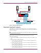
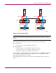
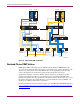
Setting Up the Dual-Switch Single-Site DRM Configuration
Note: This configuration uses only multimode, 50-micron fiber optic cable and is, therefore, limited
to 500 meters for any one connection.
Follow the procedures in Chapter 4 to configure a DRM solution, with the following
exceptions:
1. Install all required shortwave GBICs into each of the Fibre Channel switches.
2. Make the following controller connections:
a. Connect a fiber optic cable from port 1 of the top controller of Controller Pair A to
port 1 of Fibre Channel switch A.
b. Connect a fiber optic cable from port 2 of the top controller of Controller Pair A to
port 3 of Fibre Channel switch A.
c. Connect a fiber optic cable from port 1 of the bottom controller of Controller Pair A to
port 3 of Fibre Channel switch Y.
d. Connect a fiber optic cable from port 2 of the bottom controller of Controller Pair A to
port 1 of Fibre Channel switch Y.
e. Connect a fiber optic cable from port 1 of the top controller of Controller Pair Y to
port 4 of Fibre Channel switch A.
f. Connect a fiber optic cable from port 2 of the top controller of Controller Pair Y to
port 6 of Fibre Channel switch A.
g. Connect a fiber optic cable from port 1 of the bottom controller of Controller Pair Y to
port 6 of Fibre Channel switch Y.
h. Connect a fiber optic cable from port 2 of the bottom controller of Controller Pair Y to
port 4 of Fibre Channel switch Y.
Note: You should see an illuminated green LED on the switch as soon as the cable is inserted
at both ends. This verifies that there is a good connection.