
HP StorageWorks Data Replication Manager HSG80 ACS Version 8.7P Configuration Guide (AA-RPHZF-TE, March 2004)


Configuring the Optional Entry-Level DRM Solutions
156 Data Replication Manager HSG80 ACS Version 8.7P Configuration Guide
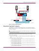
Setting Up the Single-Fabric Configuration
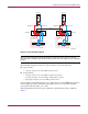
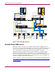
Before making any connections with the fiber optic cable, create and enable the zones that
simulate two fabrics. As Figure 24 shows, the Red Zone uses ports 0 through 3; the Blue Zone
uses ports 4 through 7 of each switch. To create zones, refer to your switch documentation.
Note: This configuration uses multimode, 50-micron fiber optic cable on the connections from the
controllers to the switches and the connections from the hosts to the switches. The ISL can use either
single-mode, 9-micron fiber or multimode, 50-micron fiber, or any supported long-distance
medium.
This procedure is a variation of the procedure provided in Chapter 4. To set up the single fabric
configuration:
1. Install all required GBICs—except those used for the ISL—into the Fibre Channel
switches, with half of the GBICs in each zone.
2. Make the following local controller connections:
a. Connect a fiber optic cable from port 1 of the top controller of Controller Pair A to
port 5 of Fibre Channel switch A.
b. Connect a fiber optic cable from port 2 of the top controller of Controller Pair A to
port 7 of Fibre Channel switch A.
c. Connect a fiber optic cable from port 1 of the bottom controller of Controller Pair A to
port 3 of Fibre Channel switch A.
d. Connect a fiber optic cable from port 2 of the bottom controller of Controller Pair A to
port 1 of Fibre Channel switch A.
3. Make the following remote controller connections:
a. Connect a fiber optic cable from port 1 of the top controller of Controller Pair Y to
port 5 of Fibre Channel switch Y.
b. Connect a fiber optic cable from port 2 of the top controller of Controller Pair Y to
port 7 of Fibre Channel switch Y.
c. Connect a fiber optic cable from port 1 of the bottom controller of Controller Pair Y to
port 3 of Fibre Channel switch Y.
d. Connect a fiber optic cable from port 2 of the bottom controller of Controller Pair Y to
port 1 of Fibre Channel switch Y.
Note: You should see an illuminated green LED on the switch as soon as the cable is inserted at both
ends. This verifies that there is a good connection.
4. Make the following local host connections:
a. Connect a fiber optic cable from HBA A of Host A to port 0 of Fibre Channel
switch A.
b. Connect a fiber optic cable from HBA B of Host A to port 6 of Fibre Channel
switch A.